EP2107322A2 - Appareil extérieur d'alimentation en eau chaude de type pompe à chaleur - Google Patents
Appareil extérieur d'alimentation en eau chaude de type pompe à chaleur Download PDFInfo
- Publication number
- EP2107322A2 EP2107322A2 EP09001048A EP09001048A EP2107322A2 EP 2107322 A2 EP2107322 A2 EP 2107322A2 EP 09001048 A EP09001048 A EP 09001048A EP 09001048 A EP09001048 A EP 09001048A EP 2107322 A2 EP2107322 A2 EP 2107322A2
- Authority
- EP
- European Patent Office
- Prior art keywords
- pressure
- refrigerant
- heat exchanger
- reduction unit
- condensing
- Prior art date
- Legal status (The legal status is an assumption and is not a legal conclusion. Google has not performed a legal analysis and makes no representation as to the accuracy of the status listed.)
- Granted
Links
Images


Classifications
-
- F—MECHANICAL ENGINEERING; LIGHTING; HEATING; WEAPONS; BLASTING
- F25—REFRIGERATION OR COOLING; COMBINED HEATING AND REFRIGERATION SYSTEMS; HEAT PUMP SYSTEMS; MANUFACTURE OR STORAGE OF ICE; LIQUEFACTION SOLIDIFICATION OF GASES
- F25B—REFRIGERATION MACHINES, PLANTS OR SYSTEMS; COMBINED HEATING AND REFRIGERATION SYSTEMS; HEAT PUMP SYSTEMS
- F25B13/00—Compression machines, plants or systems, with reversible cycle
-
- F—MECHANICAL ENGINEERING; LIGHTING; HEATING; WEAPONS; BLASTING
- F25—REFRIGERATION OR COOLING; COMBINED HEATING AND REFRIGERATION SYSTEMS; HEAT PUMP SYSTEMS; MANUFACTURE OR STORAGE OF ICE; LIQUEFACTION SOLIDIFICATION OF GASES
- F25B—REFRIGERATION MACHINES, PLANTS OR SYSTEMS; COMBINED HEATING AND REFRIGERATION SYSTEMS; HEAT PUMP SYSTEMS
- F25B40/00—Subcoolers, desuperheaters or superheaters
-
- F—MECHANICAL ENGINEERING; LIGHTING; HEATING; WEAPONS; BLASTING
- F25—REFRIGERATION OR COOLING; COMBINED HEATING AND REFRIGERATION SYSTEMS; HEAT PUMP SYSTEMS; MANUFACTURE OR STORAGE OF ICE; LIQUEFACTION SOLIDIFICATION OF GASES
- F25B—REFRIGERATION MACHINES, PLANTS OR SYSTEMS; COMBINED HEATING AND REFRIGERATION SYSTEMS; HEAT PUMP SYSTEMS
- F25B41/00—Fluid-circulation arrangements
- F25B41/30—Expansion means; Dispositions thereof
- F25B41/31—Expansion valves
- F25B41/34—Expansion valves with the valve member being actuated by electric means, e.g. by piezoelectric actuators
- F25B41/35—Expansion valves with the valve member being actuated by electric means, e.g. by piezoelectric actuators by rotary motors, e.g. by stepping motors
-
- F—MECHANICAL ENGINEERING; LIGHTING; HEATING; WEAPONS; BLASTING
- F25—REFRIGERATION OR COOLING; COMBINED HEATING AND REFRIGERATION SYSTEMS; HEAT PUMP SYSTEMS; MANUFACTURE OR STORAGE OF ICE; LIQUEFACTION SOLIDIFICATION OF GASES
- F25B—REFRIGERATION MACHINES, PLANTS OR SYSTEMS; COMBINED HEATING AND REFRIGERATION SYSTEMS; HEAT PUMP SYSTEMS
- F25B41/00—Fluid-circulation arrangements
- F25B41/30—Expansion means; Dispositions thereof
- F25B41/39—Dispositions with two or more expansion means arranged in series, i.e. multi-stage expansion, on a refrigerant line leading to the same evaporator
-
- F—MECHANICAL ENGINEERING; LIGHTING; HEATING; WEAPONS; BLASTING
- F25—REFRIGERATION OR COOLING; COMBINED HEATING AND REFRIGERATION SYSTEMS; HEAT PUMP SYSTEMS; MANUFACTURE OR STORAGE OF ICE; LIQUEFACTION SOLIDIFICATION OF GASES
- F25B—REFRIGERATION MACHINES, PLANTS OR SYSTEMS; COMBINED HEATING AND REFRIGERATION SYSTEMS; HEAT PUMP SYSTEMS
- F25B49/00—Arrangement or mounting of control or safety devices
- F25B49/02—Arrangement or mounting of control or safety devices for compression type machines, plants or systems
- F25B49/027—Condenser control arrangements
-
- F—MECHANICAL ENGINEERING; LIGHTING; HEATING; WEAPONS; BLASTING
- F25—REFRIGERATION OR COOLING; COMBINED HEATING AND REFRIGERATION SYSTEMS; HEAT PUMP SYSTEMS; MANUFACTURE OR STORAGE OF ICE; LIQUEFACTION SOLIDIFICATION OF GASES
- F25B—REFRIGERATION MACHINES, PLANTS OR SYSTEMS; COMBINED HEATING AND REFRIGERATION SYSTEMS; HEAT PUMP SYSTEMS
- F25B1/00—Compression machines, plants or systems with non-reversible cycle
- F25B1/10—Compression machines, plants or systems with non-reversible cycle with multi-stage compression
-
- F—MECHANICAL ENGINEERING; LIGHTING; HEATING; WEAPONS; BLASTING
- F25—REFRIGERATION OR COOLING; COMBINED HEATING AND REFRIGERATION SYSTEMS; HEAT PUMP SYSTEMS; MANUFACTURE OR STORAGE OF ICE; LIQUEFACTION SOLIDIFICATION OF GASES
- F25B—REFRIGERATION MACHINES, PLANTS OR SYSTEMS; COMBINED HEATING AND REFRIGERATION SYSTEMS; HEAT PUMP SYSTEMS
- F25B2400/00—Component parts or details not otherwise provided for in this subclass
- F25B2400/05—Compression system with heat exchange between particular parts of the system
- F25B2400/053—Compression system with heat exchange between particular parts of the system between the storage receiver and another part of the system
-
- F—MECHANICAL ENGINEERING; LIGHTING; HEATING; WEAPONS; BLASTING
- F25—REFRIGERATION OR COOLING; COMBINED HEATING AND REFRIGERATION SYSTEMS; HEAT PUMP SYSTEMS; MANUFACTURE OR STORAGE OF ICE; LIQUEFACTION SOLIDIFICATION OF GASES
- F25B—REFRIGERATION MACHINES, PLANTS OR SYSTEMS; COMBINED HEATING AND REFRIGERATION SYSTEMS; HEAT PUMP SYSTEMS
- F25B2400/00—Component parts or details not otherwise provided for in this subclass
- F25B2400/05—Compression system with heat exchange between particular parts of the system
- F25B2400/054—Compression system with heat exchange between particular parts of the system between the suction tube of the compressor and another part of the cycle
-
- F—MECHANICAL ENGINEERING; LIGHTING; HEATING; WEAPONS; BLASTING
- F25—REFRIGERATION OR COOLING; COMBINED HEATING AND REFRIGERATION SYSTEMS; HEAT PUMP SYSTEMS; MANUFACTURE OR STORAGE OF ICE; LIQUEFACTION SOLIDIFICATION OF GASES
- F25B—REFRIGERATION MACHINES, PLANTS OR SYSTEMS; COMBINED HEATING AND REFRIGERATION SYSTEMS; HEAT PUMP SYSTEMS
- F25B2400/00—Component parts or details not otherwise provided for in this subclass
- F25B2400/13—Economisers
-
- F—MECHANICAL ENGINEERING; LIGHTING; HEATING; WEAPONS; BLASTING
- F25—REFRIGERATION OR COOLING; COMBINED HEATING AND REFRIGERATION SYSTEMS; HEAT PUMP SYSTEMS; MANUFACTURE OR STORAGE OF ICE; LIQUEFACTION SOLIDIFICATION OF GASES
- F25B—REFRIGERATION MACHINES, PLANTS OR SYSTEMS; COMBINED HEATING AND REFRIGERATION SYSTEMS; HEAT PUMP SYSTEMS
- F25B2400/00—Component parts or details not otherwise provided for in this subclass
- F25B2400/16—Receivers
-
- F—MECHANICAL ENGINEERING; LIGHTING; HEATING; WEAPONS; BLASTING
- F25—REFRIGERATION OR COOLING; COMBINED HEATING AND REFRIGERATION SYSTEMS; HEAT PUMP SYSTEMS; MANUFACTURE OR STORAGE OF ICE; LIQUEFACTION SOLIDIFICATION OF GASES
- F25B—REFRIGERATION MACHINES, PLANTS OR SYSTEMS; COMBINED HEATING AND REFRIGERATION SYSTEMS; HEAT PUMP SYSTEMS
- F25B2600/00—Control issues
- F25B2600/17—Control issues by controlling the pressure of the condenser
-
- F—MECHANICAL ENGINEERING; LIGHTING; HEATING; WEAPONS; BLASTING
- F25—REFRIGERATION OR COOLING; COMBINED HEATING AND REFRIGERATION SYSTEMS; HEAT PUMP SYSTEMS; MANUFACTURE OR STORAGE OF ICE; LIQUEFACTION SOLIDIFICATION OF GASES
- F25B—REFRIGERATION MACHINES, PLANTS OR SYSTEMS; COMBINED HEATING AND REFRIGERATION SYSTEMS; HEAT PUMP SYSTEMS
- F25B2600/00—Control issues
- F25B2600/21—Refrigerant outlet evaporator temperature
-
- F—MECHANICAL ENGINEERING; LIGHTING; HEATING; WEAPONS; BLASTING
- F25—REFRIGERATION OR COOLING; COMBINED HEATING AND REFRIGERATION SYSTEMS; HEAT PUMP SYSTEMS; MANUFACTURE OR STORAGE OF ICE; LIQUEFACTION SOLIDIFICATION OF GASES
- F25B—REFRIGERATION MACHINES, PLANTS OR SYSTEMS; COMBINED HEATING AND REFRIGERATION SYSTEMS; HEAT PUMP SYSTEMS
- F25B2600/00—Control issues
- F25B2600/25—Control of valves
- F25B2600/2509—Economiser valves
-
- F—MECHANICAL ENGINEERING; LIGHTING; HEATING; WEAPONS; BLASTING
- F25—REFRIGERATION OR COOLING; COMBINED HEATING AND REFRIGERATION SYSTEMS; HEAT PUMP SYSTEMS; MANUFACTURE OR STORAGE OF ICE; LIQUEFACTION SOLIDIFICATION OF GASES
- F25B—REFRIGERATION MACHINES, PLANTS OR SYSTEMS; COMBINED HEATING AND REFRIGERATION SYSTEMS; HEAT PUMP SYSTEMS
- F25B2600/00—Control issues
- F25B2600/25—Control of valves
- F25B2600/2513—Expansion valves
-
- F—MECHANICAL ENGINEERING; LIGHTING; HEATING; WEAPONS; BLASTING
- F25—REFRIGERATION OR COOLING; COMBINED HEATING AND REFRIGERATION SYSTEMS; HEAT PUMP SYSTEMS; MANUFACTURE OR STORAGE OF ICE; LIQUEFACTION SOLIDIFICATION OF GASES
- F25B—REFRIGERATION MACHINES, PLANTS OR SYSTEMS; COMBINED HEATING AND REFRIGERATION SYSTEMS; HEAT PUMP SYSTEMS
- F25B2700/00—Sensing or detecting of parameters; Sensors therefor
- F25B2700/19—Pressures
- F25B2700/193—Pressures of the compressor
- F25B2700/1931—Discharge pressures
-
- F—MECHANICAL ENGINEERING; LIGHTING; HEATING; WEAPONS; BLASTING
- F25—REFRIGERATION OR COOLING; COMBINED HEATING AND REFRIGERATION SYSTEMS; HEAT PUMP SYSTEMS; MANUFACTURE OR STORAGE OF ICE; LIQUEFACTION SOLIDIFICATION OF GASES
- F25B—REFRIGERATION MACHINES, PLANTS OR SYSTEMS; COMBINED HEATING AND REFRIGERATION SYSTEMS; HEAT PUMP SYSTEMS
- F25B2700/00—Sensing or detecting of parameters; Sensors therefor
- F25B2700/21—Temperatures
- F25B2700/2117—Temperatures of an evaporator
- F25B2700/21174—Temperatures of an evaporator of the refrigerant at the inlet of the evaporator
-
- F—MECHANICAL ENGINEERING; LIGHTING; HEATING; WEAPONS; BLASTING
- F25—REFRIGERATION OR COOLING; COMBINED HEATING AND REFRIGERATION SYSTEMS; HEAT PUMP SYSTEMS; MANUFACTURE OR STORAGE OF ICE; LIQUEFACTION SOLIDIFICATION OF GASES
- F25B—REFRIGERATION MACHINES, PLANTS OR SYSTEMS; COMBINED HEATING AND REFRIGERATION SYSTEMS; HEAT PUMP SYSTEMS
- F25B41/00—Fluid-circulation arrangements
- F25B41/30—Expansion means; Dispositions thereof
- F25B41/385—Dispositions with two or more expansion means arranged in parallel on a refrigerant line leading to the same evaporator
-
- Y—GENERAL TAGGING OF NEW TECHNOLOGICAL DEVELOPMENTS; GENERAL TAGGING OF CROSS-SECTIONAL TECHNOLOGIES SPANNING OVER SEVERAL SECTIONS OF THE IPC; TECHNICAL SUBJECTS COVERED BY FORMER USPC CROSS-REFERENCE ART COLLECTIONS [XRACs] AND DIGESTS
- Y02—TECHNOLOGIES OR APPLICATIONS FOR MITIGATION OR ADAPTATION AGAINST CLIMATE CHANGE
- Y02B—CLIMATE CHANGE MITIGATION TECHNOLOGIES RELATED TO BUILDINGS, e.g. HOUSING, HOUSE APPLIANCES OR RELATED END-USER APPLICATIONS
- Y02B30/00—Energy efficient heating, ventilation or air conditioning [HVAC]
- Y02B30/70—Efficient control or regulation technologies, e.g. for control of refrigerant flow, motor or heating
Definitions
- the present invention relates to a heat pump type hot water supply outdoor apparatus having a water heat exchanger and an injection circuit.
- the conventional air conditioner having the injection circuit determines whether or not an injection control is carried out based on an outside air temperature during a heating operation.
- the injection control is carried out to exhibit an advantage of obtaining a high heating capability at the time when the ratio (compression ratio) between the pressure (high pressure) of the refrigerant discharged from a compressor and the pressure (low pressure) of the refrigerant sucked into the compressor. Accordingly, when an outside air temperature is reduced at the time when the air conditioner carries out the heating operation, the compression ratio is increased because an evaporation temperature is reduced and a suction pressure is also reduced. Thus, the injection control is carried out when the outside air temperature is reduced.
- a condensing temperature corresponding to the high pressure changes within the wide range of from 20°C to 65°C or more.
- a problem arises in that a capability becomes insufficient because the injection control is not carried out regardless of a condition that the compression ratio is high or the capability is excessively increased because the injection control is carried out in a condition that the compression ratio is low.
- the heat pump type hot water supply outdoor apparatus has a problem in that an optimum injection control cannot be realized only by the outside air temperature.
- An object of the present invention which was made to solve the above problems, is to obtain a heat pump type hot water supply outdoor apparatus which can realize an appropriate injection control, can permit a long period of time of use of equipment because the reliability thereof can be secured even if an outside air temperature and the temperature of supplied hot water change, can carry out a high hot water supply/heating capability operation or a highly effective hot water supply/heating operation, and can reduce energy consumption.
- a heat pump type hot water supply outdoor apparatus in which a compressor, a water heat exchanger for carrying out heat exchange between water and refrigerant, a first pressure reduction unit, a medium pressure receiver, a second pressure reduction unit, and an air heat exchanger for carrying out heat exchange between air and refrigerant are connected circularly, heat is supplied from outside air by the air heat exchanger, and heat is supplied to water by the water heat exchanger, has an injection circuit, a pressure detection sensor and a controller.
- the injection circuit is a bypass for a part of the refrigerant between the medium pressure receiver and the second pressure reduction unit to inject the part of refrigerant into a compression chamber of the compressor, and has a third pressure reduction unit and an internal heat exchanger for carrying out heat exchange between the refrigerant whose pressure is reduced by the third pressure reduction unit and the refrigerant between the medium pressure receiver and the second pressure reduction unit.
- the pressure detection sensor is disposed in the vicinity of an discharge port of the compressor and detects the condensing pressure of the refrigerant.
- the controller carries out a control for starting an injection control at the time when a condensing pressure detected by the pressure detection sensor or a condensing temperature calculated from the condensing pressure becomes a first predetermined value or more, and stopping the injection control at the time when the condensing pressure detected by the pressure detection sensor or the condensing temperature calculate from the condensing pressure becomes a second predetermined value, which is smaller than the first predetermined value, or less.
- the injection control is carried out appropriately by proper determination based on the condensing pressure or the condensing temperature calculated from the condensing pressure, so that the heat pump type hot water supply outdoor apparatus is advantageous in that an appropriate injection control can be carried out, equipment can be used for a long period of time because the reliability thereof can be secured even at the time when an outside air temperature and the temperature of supplied hot water change, a high hot water supply/heating capability operation or a highly effective hot water supply/heating operation can be carried out, and energy consumption can be reduced.
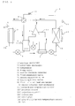
- Fig. 1 is a refrigerant circuit diagram of a heat pump type hot water supply outdoor apparatus of an embodiment 1 of the present invention
- Fig. 2 is a PH graph showing an operating state of the hot water supply/heating operation in which the heat pump type hot water supply outdoor apparatus does not carry out injection
- Fig. 3 is a PH graph showing an operating state of the hot water supply/heating operation in which the heat pump type hot water supply outdoor apparatus carries out the injection
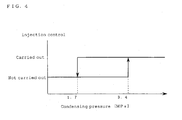
- Fig. 4 is a transition view showing whether or not an injection control is carried out according to a condensing pressure of the heat pump type hot water supply outdoor apparatus
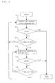
- Fig. 5 is a flowchart showing an injection control operation of the heat pump type hot water supply outdoor apparatus.
- An injection circuit 13 has one end connected between the medium pressure receiver 5 and the first internal heat exchanger 9 and the other end connected to an injection port of the compressor 3.
- the injection circuit 13 is composed of a third expansion valve 8 for adjusting a flow amount of the refrigerant and reducing its pressure, and the first internal heat exchanger 9, connected through a pipe. Further, a water pipe 15 is connected to the water heat exchanger 2, and water flows in the water pipe 15 and the water heat exchanger 2.
- the medium pressure receiver 5 has a function for holding the excessive refrigerant in the circuit and a function as the second internal heat exchanger 10 at the same time. The circuit can be arranged even if the suction pipe is not caused to pass through inside of the medium pressure receiver 5. In this case, the medium pressure receiver 5 does not have the function as the second internal heat exchanger.
- the compressor 3 is of such a type that the capacity thereof is controlled by controlling the number of revolutions thereof by an inverter and has such a structure that the refrigerant can be supplied from the injection circuit 13 into a compression chamber in the compressor 3.
- the first expansion valve 6, the second expansion valve 7, and the third expansion valve 8 are electronic expansion valves whose degrees of opening are variably controlled. Air is supplied to the air heat exchanger 1 by a fan 19 and the like and heat exchange with outside air is carried out.
- R410A or R407C which is HFC mixed refrigerant, is used as the refrigerant of the heat pump type hot water supply outdoor apparatus.
- a controller 14 is installed in the heat pump type hot water supply outdoor apparatus of the embodiment 1.
- a refrigerant circuit has a liquid refrigerant temperature sensor 16 interposed between the second expansion valve 7 and the air heat exchanger 1, to measure a refrigerant temperature at the installation position of the sensor. Further, an outside air temperature sensor 11 measures an outside air temperature around the outdoor apparatus. The temperatures measured by the respective temperature sensors are supplied to the controller 14.
- a pressure sensor 12 is disposed to a pipe for connecting the discharge side of the compressor 3 to the 4-way valve 4 for switching the hot water supply/heating operation and defrost operation and detects the pressure of discharged refrigerant.
- a pipe from the pressure sensor 12 to the water heat exchanger 2 or the air heat exchanger 1 has a short length. Since the pipe has a small pressure loss, the pressure detected by the pressure sensor 12 is equal to the condensing pressure of the refrigerant in the water heat exchanger 2 or in the air heat exchanger 1.
- the condensing temperature of the refrigerant can be calculated from the condensing pressure.
- the controller 14 controls an operation method of the compressor 3, switching of a flow path of the 4-way valve 4, the amount of air supplied by the fan of the air heat exchanger 1, the degrees of opening of the first expansion valve 6, the second expansion valve 7, and the third expansion valve 8, and the like based on the measurement information of the outside air temperature sensor 11, the liquid refrigerant temperature sensor 16, and the pressure sensor 12 and on the operation contents instructed by a user of the heat pump type hot water supply outdoor apparatus.
- a hot water supply/heating operation in which an injection control is not carried out, will be explained based on the refrigerant circuit diagram shown in Fig. 1 and the PH graph in the hot water supply/heating operation shown in Fig. 2 .
- the flow path of the 4-way valve 4 is set in solid line directions shown in Fig. 1 .
- the high temperature and high pressure gas refrigerant (point a of Fig. 2 ) discharged from the compressor 3 flows into the water heat exchanger 2 through the 4-way valve 4.
- the gas refrigerant is condensed and liquefied while radiating heat in the water heat exchanger 2 acting as a condenser and is made to high pressure and low temperature liquid refrigerant (point b of Fig. 2 ).
- the heat radiated from the refrigerant is applied to the water on a load side that flows in the water pipe 15 to thereby heat the water.
- the high pressure and low temperature refrigerant from the water heat exchanger 2 is reduced in pressure by the first expansion valve 6 (point c of Fig. 2 ), it is made to gas-liquid two-phase refrigerant and flows into the medium pressure receiver 5.
- the high pressure and low temperature refrigerant is cooled by radiating heat to the low temperature refrigerant sucked by the compressor 3, in the medium pressure receiver 5 that functions as the second internal heat exchanger 10 (point d of Fig. 2 ) and flows out as liquid refrigerant. All the refrigerant from the medium pressure receiver 5 flows into the first internal heat exchanger 9 without branching off into the injection circuit 13 because the third expansion valve 8 in the injection circuit 13 is closed. Since the refrigerant does not flow to the injection circuit 13, it flows to the second expansion valve 7 without being subjected to heat exchange in the first internal heat exchanger 9. The refrigerant is reduced in pressure and made to two-phase refrigerant (point f of Fig.
- the second expansion valve 7 by the second expansion valve 7 and then flows into the air heat exchanger 1 acting as an evaporator in which it is evaporated and gasified by absorbing heat(point g of Fig. 2 ). Thereafter, the gasified refrigerant passes through the 4-way valve 4, is subjected to heat exchange with high pressure refrigerant in the medium pressure receiver 5 by the function thereof as the second internal heat exchanger 10, is further heated (point h of Fig. 2 ), and is sucked by the compressor 3. The refrigerant sucked by the compressor 3 is compressed thereby, made to high temperature and high pressure gas refrigerant (point a of Fig. 2 ), and discharged from the compressor 3, and the same cycle is repeated.
- a hot water supply/heating operation in which the injection control is carried out, will be explained based on the refrigerant circuit diagram shown in Fig. 1 and the PH graph in the hot water supply/heating operation shown in Fig. 3 .
- the flow path of the 4-way valve 4 is set in the solid line directions shown in Fig. 1 .
- the high temperature and high pressure gas refrigerant (point a of Fig. 3 ) discharged from the compressor 3 flows into the water heat exchanger 2 through the 4-way valve 4.
- the gas refrigerant is condensed and liquefied while radiating heat in the water heat exchanger 2 acting as the condenser and is made to high pressure and low temperature liquid refrigerant (point b of Fig. 3 ).
- the heat radiated from the refrigerant is applied to the water on the load side that flow in the water pipe 15 to thereby heat the water.
- the high pressure and low temperature refrigerant from the water heat exchanger 2 is reduced in pressure by the first expansion valve 6 (point c of Fig. 3 ), it is made to gas-liquid two-phase refrigerant and flows into the medium pressure receiver 5.
- the high pressure and low temperature refrigerant is cooled by radiating heat to the low temperature refrigerant sucked by the compressor 3 in the medium pressure receiver 5 that functions as the second internal heat exchanger 10 (point d of Fig. 3 ) and flows out as liquid refrigerant. Since the third expansion valve 8 in the injection circuit 13 is opened, the refrigerant from the medium pressure receiver 5 partially branches off into the injection circuit 13, the rest of the refrigerant flows into the first internal heat exchanger 9, is subjected to heat exchange with the refrigerant in the injection circuit 13 having the pressure and the temperature reduced by the third expansion valve 8, and is further cooled (point e of Fig. 3 ).
- the refrigerant is reduced in pressure to a low level and made to two-phase refrigerant (point f of Fig. 2 ) by the second expansion valve 7 and thereafter flows into the air heat exchanger 1 acting as the evaporator in which it is evaporated and gasified by absorbing the heat (point g of Fig. 3 ).
- the gasified refrigerant passing through the 4-way valve 4 is subjected to heat exchange with high pressure refrigerant in the medium pressure receiver 5 by the function thereof as the second internal heat exchanger 10, is further heated (point h of Fig. 3 ), and sucked by the compressor 3.
- the refrigerant branching off into the injection circuit 13 is reduced in pressure to a medium level by the third expansion valve 8, made to low temperature two-phase refrigerant (point i of Fig. 3 ), thereafter subjected to heat exchange with high pressure refrigerant by the first internal heat exchanger 9 (point j of Fig. 3 ), and injected into the compressor 3.
- the compressor 3 after the sucked refrigerant (point h of Fig. 3 ) is compressed to a medium pressure and heated (point 1 of Fig. 3 ), it joins the injected refrigerant, is compressed to a high pressure after the temperature thereof is reduced (point k of Fig. 3 ), made to high pressure gas refrigerant (point a of Fig. 3 ), and injected from the compressor 3, and the same cycle is repeated.
- the temperature of the refrigerant injected from the compressor 3 can be reduced even in an operation in which the ratio between the high pressure and the low pressure (compression ratio) is high, the number of revolutions of the compressor 3 can be increased in operation, and the high hot water supply/heating capability can be obtained.
- the operation is carried out at a low compression ratio, the temperature of the refrigerant discharged from the compressor 3 is reduced, by which the life of the compressor 3 may be shortened.
- the operations having the two types of features in a case that the injection control is carried out and is not carried out can be carried out. Accordingly, equipment can be used for a long period of time because reliability can be secured by appropriately determining whether or not the injection control is carried out. Further, a high hot water supply/heating capability operation can be carried out or a highly effective hot water supply/heating operation can be carried out, and energy consumption can be reduced.
- a conventional air conditioner determines whether or not the injection control is carried out according to an outside air temperature detected by an outside air temperature sensor.
- an outside air temperature is reduced to 3°C or less
- the injection control is carried out by opening the third expansion valve so that a high heating capability is exhibited. This is because that since a condensing temperature corresponding to a high pressure at the time when the air conditioner is used for a heating operation, only changes in the range of from about 35°C to 50°C, a state in which a compression ratio is high can be assumed at an outside air temperature by which a low pressure is determined.
- the heat pump type hot water supply outdoor apparatus of the embodiment 1 of the present invention can carry out the injection control when "the condensing pressure detected by the pressure sensor 12" becomes a predetermined value, for example, 3.4 MPa (corresponding to about 55°C in terms of a condensing temperature) or more. Therefore, the high hot water supply/heating capability can be obtained even in a state of the outside air temperature of 10°C that is higher than 3°C. Further, the same advantage can be obtained even if the injection control is carried out at the time when "the condensing temperature calculated from the condensing pressure detected by the pressure sensor 12" becomes a predetermined value, for example, 55°C or more.
- the condensing temperature can be determined from condensing temperature by calculation, whether or not the injection control is carried out can be also determined from the ratio between the condensing temperature and the evaporation temperature by detecting the evaporation temperature.
- the same advantage can be obtained even if the injection control is carried out at the time when the ratio between "the condensing temperature calculated from the condensing pressure detected by the pressure sensor 12" and "the evaporation temperature detected by the liquid refrigerant temperature sensor 16" becomes a predetermined value or more.
- the temperatures may have a minus value, so that the determination needs to be carried out from the ratio of, for example, the condensing temperature +50°C and the evaporation temperature +50°C.
- (60 + 50)/(7 + 50) 1.93. Accordingly, the same advantage can be obtained even if the injection control is carried out at the ratio of, for example, 1.8 or more.
- the same advantage can be obtained even if the injection control is carried out at the time when the difference between "the condensing pressure detected by the pressure sensor 12" and "the evaporation pressure calculated from the evaporation temperature detected by the liquid refrigerant temperature sensor 16" becomes a predetermined value or more.
- 3.8 - 1.0 2.8. Accordingly, the same advantage can be obtained even if the injection control is carried out at the time when the difference becomes, for example, 2.0 or more.
- the same advantage can be obtained even if the injection control is carried out at the time when the difference between "the condensing temperature calculated from the condensing pressure detected by the pressure sensor 12" and "the evaporation temperature detected by the liquid refrigerant temperature sensor 16 " becomes a predetermined value or more.
- 60 -7 53. Accordingly, the same advantage can be obtained even if the injection control is carried out at the time when the difference becomes, for example, 45 or more.
- the injection control is appropriately carried out when the compression ratio becomes a predetermined value or more.
- it will be explained here that there is a case in which it is appropriate not to carry out the injection control when the compression ratio becomes a predetermined value or less.
- an operation carried out at, for example, an outside air temperature of 0°C and a condensing temperature of 20°C since the condensing pressure (high pressure) becomes about 1.4MPa, and the evaporation pressure (low pressure) becomes about 0.7 MPa (evaporation temperature becomes about -3°C), an operation is carried out at a low compression ratio of 2.0.
- the hot water supply/ heating capability becomes excessively large and the temperature of the refrigerant discharged from the compressor 3 is reduced by the injection control.
- the life of the compressor 3 may be shortened as a result.
- a predetermined value for example, 1.7MPa (corresponding to about 26°C in terms of the condensing temperature) or less.
- the same advantage can be obtained” even if the injection control is not carried out at the time when the ratio between the condensing pressure detected by the pressure sensor 12" and "the evaporation pressure calculated from the evaporation temperature detected by the liquid refrigerant temperature sensor 16" becomes a predetermined value or less.
- the same advantage can be obtained even if the injection control is not carried out at the ratio of, for example, 2.2 or less.
- the same advantage can be obtained even if the injection control is not carried out at the time when the ratio between "the condensing temperature calculated from the condensing pressure detected by the pressure sensor 12" and "the evaporation temperature detected by the liquid refrigerant temperature sensor 16" becomes a predetermined value or less.
- the temperatures may have a minus value, so that the determination needs to be carried out from the ratio of, for example, the condensing temperature + 50°C and the evaporation temperature + 50°C.
- (20 + 50)/(- 3 + 50) 1.49. Accordingly, the same advantage can be obtained even if the injection control is not carried out at the time when the ratio is, for example, 1.55 or less.
- the same advantage can be obtained, even if the injection control is not carried out at the time when the difference between "the condensing pressure detected by the pressure sensor 12" and "the evaporation pressure calculated from the evaporation temperature detected by the liquid refrigerant temperature sensor 16" becomes a predetermined value or less.
- 1.4 - 0.7 0.7. Accordingly, the same advantage can be obtained even if the injection control is not carried out at the time when the difference becomes, for example, 1.0 or less.
- the same advantage can be obtained even if the injection control is not carried out at the time when the difference between "the condensing temperature calculated from the condensing pressure detected by the pressure sensor 12" and "the evaporation temperature detected by the liquid refrigerant temperature sensor 16" becomes a predetermined value or less.
- 20 - (-3) 23. Accordingly, the same advantage can be obtained even if the injection control is not carried out at the time when the difference is, for example, 30 or less.
- the injection control will be summarized from the above explanation as described below. There is examined a case in which the injection control is carried out at the time when, for example, "the condensing pressure detected by the pressure sensor 12" becomes 3.4 MPa (corresponding to about 55°C in terms of the condensing temperature) or more and the injection control is not carried out at the time when "the condensing pressure detected by the pressure sensor 12" becomes 1.7 MPa (corresponding to about 26°C in terms of the condensing temperature) or less. Then, when the condensing pressure is 1.7 MPa or more and 3.4 MPa or less, a previous state is held. A transition state in this case is as shown in Fig. 5 . Note that when the heat pump type hot water supply outdoor apparatus is started up, the condensing pressure is not increased so that the injection control is not carried out.
- step S1 When the heat pump type hot water supply outdoor apparatus of the embodiment 1 is started up, it goes to a mode in which the injection control is not carried out (step S1). Next, whether or not a stop command is issued is determined (step S2), and when the stop command is issued, the heat pump type hot water supply outdoor apparatus is stopped, whereas when the stop command is not issued, the mode goes to a pressure determination mode.
- step S3 whether or not a pressure is 3.4 MPa or more is determined (step S3), and when the pressure is 3.4 MPa or more, the pressure determination mode goes to a mode for carrying out the injection control (step S4), whereas when the pressure is less than 3.4 MPa, the process returns to step S1 at which a mode for not carrying out the injection control is continued.
- step S5 whether or not the stop command is issued is determined while the injection control is being carried out, and when the stop command is issued, the heat pump type hot water supply outdoor apparatus is stopped, whereas when the stop command is not issued, the mode goes to another pressure determination mode.
- step S6 whether or not the pressure is 1.7 MPa or less is determined (step S6), and when the pressure is equal to or less than 1.7 MPa, the process returns to step S1 which is the mode for not carrying out the injection control. Further, when the pressure exceeds 1.7 MPa, the mode for carrying out the injection control is continued.
- the injection control can be optimumly carried out by repeating the above steps. Whether or not the injection control is carried out is appropriately determined as described above. Since reliability can be secured even at the time when an outside air temperature and the temperature of supplied hot water change, the equipment can be used for a long period of time. Further, the high hot water supply/heating capability operation can be carried out or the highly effective hot water supply/heating operation can be carried out, and the energy consumption can be reduced.
- Fig. 6 is a refrigerant circuit diagram of a heat pump type hot water supply outdoor apparatus of an embodiment 2 of the present invention.
- the same constituents as those of the embodiment 1 are denoted by the same reference numerals, and explanation of the duplicate constituents is omitted.
- an injection circuit 13 is provided with a capillary tube 17 for adjusting the flow amount of refrigerant and reducing its pressure and an electromagnetic valve 18 for closing the flow of the refrigerant in place of the third expansion valve 8 in the injection circuit 13 of the embodiment 1.
- the embodiment 2 is arranged to have a pressure sensor 12 and a liquid refrigerant temperature sensor 16 for detecting a liquid refrigerant temperature in an evaporator likewise the embodiment 1.
- an electromagnetic valve 18 is opened or closed, on the basis of "the condensing pressure detected by the pressure sensor 12" or “the condensing temperature calculated from the condensing pressure detected by the pressure sensor 12", the ratio between “the condensing pressure detected by the pressure sensor 12” and “the evaporation pressure calculated from the evaporation temperature detected by the liquid refrigerant temperature sensor 16", the ratio between “the condensing temperature calculated from the condensing pressure detected by the pressure sensor 12” and “the evaporation temperature detected by the liquid refrigerant temperature sensor 16", the difference between "the condensing pressure detected by the pressure sensor 12” and “the evaporation pressure calculated from the evaporation temperature detected by the liquid refrigerant temperature sensor 16", or the difference between "the condensing temperature calculated from the condensing pressure detected by the pressure sensor 12" and “the evaporation temperature detected by the liquid refrigerant temperature sensor 16", likewise the embodiment 1.
- the air heat exchanger 1 is defrosted in a defrost operation by circulating the refrigerant discharged from the compressor 3 in the sequence of the air heat exchanger 1, the second expansion valve 7, the medium pressure receiver 5, the first expansion valve 6, and the water heat exchanger 2, through the 4-way valve 4 by operating it.
Landscapes
- Engineering & Computer Science (AREA)
- Physics & Mathematics (AREA)
- Mechanical Engineering (AREA)
- Thermal Sciences (AREA)
- General Engineering & Computer Science (AREA)
- Heat-Pump Type And Storage Water Heaters (AREA)
Priority Applications (1)
| Application Number | Priority Date | Filing Date | Title |
|---|---|---|---|
| EP12180895.0A EP2527764A3 (fr) | 2008-03-31 | 2009-01-26 | Appareil extérieur d'alimentation en eau chaude de type pompe à chaleur |
Applications Claiming Priority (1)
| Application Number | Priority Date | Filing Date | Title |
|---|---|---|---|
| JP2008091634A JP4931848B2 (ja) | 2008-03-31 | 2008-03-31 | ヒートポンプ式給湯用室外機 |
Related Child Applications (2)
| Application Number | Title | Priority Date | Filing Date |
|---|---|---|---|
| EP12180895.0A Division EP2527764A3 (fr) | 2008-03-31 | 2009-01-26 | Appareil extérieur d'alimentation en eau chaude de type pompe à chaleur |
| EP12180895.0A Division-Into EP2527764A3 (fr) | 2008-03-31 | 2009-01-26 | Appareil extérieur d'alimentation en eau chaude de type pompe à chaleur |
Publications (3)
| Publication Number | Publication Date |
|---|---|
| EP2107322A2 true EP2107322A2 (fr) | 2009-10-07 |
| EP2107322A3 EP2107322A3 (fr) | 2012-06-27 |
| EP2107322B1 EP2107322B1 (fr) | 2019-03-27 |
Family
ID=40796213
Family Applications (2)
| Application Number | Title | Priority Date | Filing Date |
|---|---|---|---|
| EP12180895.0A Withdrawn EP2527764A3 (fr) | 2008-03-31 | 2009-01-26 | Appareil extérieur d'alimentation en eau chaude de type pompe à chaleur |
| EP09001048.9A Not-in-force EP2107322B1 (fr) | 2008-03-31 | 2009-01-26 | Appareil extérieur d'alimentation en eau chaude de type pompe à chaleur |
Family Applications Before (1)
| Application Number | Title | Priority Date | Filing Date |
|---|---|---|---|
| EP12180895.0A Withdrawn EP2527764A3 (fr) | 2008-03-31 | 2009-01-26 | Appareil extérieur d'alimentation en eau chaude de type pompe à chaleur |
Country Status (3)
| Country | Link |
|---|---|
| US (1) | US8020393B2 (fr) |
| EP (2) | EP2527764A3 (fr) |
| JP (1) | JP4931848B2 (fr) |
Cited By (6)
| Publication number | Priority date | Publication date | Assignee | Title |
|---|---|---|---|---|
| WO2011097748A2 (fr) | 2010-02-12 | 2011-08-18 | Frigotech Uwe Kolschen, Ideen + Systeme | Pompe à chaleur |
| WO2013004233A1 (fr) * | 2011-07-05 | 2013-01-10 | Danfoss A/S | Procédé pour commander le fonctionnement d'un système de compression de vapeur dans un mode sous-critique et dans un mode supercritique |
| CN103398518A (zh) * | 2011-05-06 | 2013-11-20 | 荣国华 | 储液器 |
| EP2672201A4 (fr) * | 2011-01-31 | 2016-12-07 | Mitsubishi Electric Corp | Dispositif de climatisation |
| EP2672199A4 (fr) * | 2011-01-31 | 2016-12-14 | Mitsubishi Electric Corp | Dispositif de climatisation |
| CN111247377A (zh) * | 2017-10-27 | 2020-06-05 | 三菱电机株式会社 | 制冷循环装置 |
Families Citing this family (45)
| Publication number | Priority date | Publication date | Assignee | Title |
|---|---|---|---|---|
| KR101241222B1 (ko) | 2011-07-21 | 2013-03-13 | 기아자동차주식회사 | 차량용 히트펌프 시스템 제어방법 |
| JP5570531B2 (ja) * | 2010-01-26 | 2014-08-13 | 三菱電機株式会社 | ヒートポンプ装置 |
| CN102844630B (zh) | 2010-04-05 | 2015-01-28 | 三菱电机株式会社 | 空调热水供给复合系统 |
| JP2012026610A (ja) * | 2010-07-21 | 2012-02-09 | Mitsubishi Electric Corp | 冷媒回路システム |
| MY161767A (en) * | 2010-12-14 | 2017-05-15 | Du Pont | Combinations of e-1,3,3,3-tetrafluoropropene and at least one tetrafluoroethane and their use for heating |
| KR101750867B1 (ko) | 2011-01-21 | 2017-07-03 | 엘지전자 주식회사 | 공기열원 급탕기 및 그의 운전제어방법 |
| GB201102473D0 (en) * | 2011-02-11 | 2011-03-30 | Esg Pool Ventilation Ltd | Heating and cooling system and related methods |
| KR101241223B1 (ko) | 2011-03-23 | 2013-03-25 | 기아자동차주식회사 | 차량용 히트펌프 시스템 및 그 제어방법 |
| CN102226542B (zh) * | 2011-06-03 | 2014-04-23 | 北京建筑工程学院 | 一种引射式热泵型换热机组 |
| CN102269457A (zh) * | 2011-07-15 | 2011-12-07 | 广东同益电器有限公司 | 直流换热式全效热水空调系统 |
| WO2013111176A1 (fr) * | 2012-01-23 | 2013-08-01 | 三菱電機株式会社 | Dispositif de climatisation |
| CN103245155A (zh) * | 2012-02-14 | 2013-08-14 | 珠海格力节能环保制冷技术研究中心有限公司 | 双级增焓热泵系统控制方法 |
| JP5500240B2 (ja) * | 2012-05-23 | 2014-05-21 | ダイキン工業株式会社 | 冷凍装置 |
| WO2014036835A1 (fr) * | 2012-09-06 | 2014-03-13 | 江苏天舒电器有限公司 | Chauffe-eau à pompe à chaleur équipé d'un système de traitement équilibré à utilisation de chaleur, et système de traitement équilibré à utilisation de chaleur de celui-ci |
| US9982929B2 (en) * | 2012-11-20 | 2018-05-29 | Samsung Electronics Co., Ltd. | Air conditioner |
| EP2924367B1 (fr) * | 2012-11-21 | 2021-11-03 | Mitsubishi Electric Corporation | Dispositif de climatisation |
| KR102163859B1 (ko) * | 2013-04-15 | 2020-10-12 | 엘지전자 주식회사 | 공기조화기 및 그 제어방법 |
| WO2015004747A1 (fr) * | 2013-07-10 | 2015-01-15 | 三菱電機株式会社 | Appareil à cycle frigorifique |
| JP6241595B2 (ja) | 2013-08-23 | 2017-12-06 | サンデンホールディングス株式会社 | 車両用空気調和装置 |
| TWI539120B (zh) * | 2013-12-06 | 2016-06-21 | 財團法人工業技術研究院 | 具除濕與除霜功能之裝置及其控制方法 |
| KR102240070B1 (ko) * | 2014-03-20 | 2021-04-13 | 엘지전자 주식회사 | 공기조화기 및 그 제어방법 |
| JP6418779B2 (ja) * | 2014-05-08 | 2018-11-07 | サンデンホールディングス株式会社 | 車両用空気調和装置 |
| US9976785B2 (en) * | 2014-05-15 | 2018-05-22 | Lennox Industries Inc. | Liquid line charge compensator |
| US10330358B2 (en) | 2014-05-15 | 2019-06-25 | Lennox Industries Inc. | System for refrigerant pressure relief in HVAC systems |
| EP3023713A1 (fr) * | 2014-11-19 | 2016-05-25 | Danfoss A/S | Procédé pour commander un système de compression de vapeur avec un éjecteur |
| JP2016211830A (ja) * | 2015-05-13 | 2016-12-15 | 多門 山内 | 温冷両熱同時獲得保存装置の無駄を無くし効果をより高める方法 |
| WO2017029011A1 (fr) | 2015-08-14 | 2017-02-23 | Danfoss A/S | Système à compression de vapeur doté d'au moins deux groupes évaporateurs |
| MX374485B (es) | 2015-10-20 | 2025-03-06 | Danfoss As | Metodo para controlar un sistema de compresion de vapor en modo de eyector durante un tiempo prolongado. |
| CN108139132B (zh) | 2015-10-20 | 2020-08-25 | 丹佛斯有限公司 | 用于控制有可变接收器压力设定点的蒸气压缩系统的方法 |
| KR101854335B1 (ko) | 2016-01-18 | 2018-05-03 | 엘지전자 주식회사 | 공기조화기 |
| US11820933B2 (en) | 2017-12-18 | 2023-11-21 | Daikin Industries, Ltd. | Refrigeration cycle apparatus |
| US11906207B2 (en) | 2017-12-18 | 2024-02-20 | Daikin Industries, Ltd. | Refrigeration apparatus |
| US12270575B2 (en) | 2017-12-18 | 2025-04-08 | Daikin Industries, Ltd. | Warm-water generating apparatus |
| US12379140B2 (en) | 2017-12-18 | 2025-08-05 | Daikin Industries., Ltd. | Air conditioner |
| CN111511874A (zh) * | 2017-12-18 | 2020-08-07 | 大金工业株式会社 | 制冷循环装置 |
| US10663199B2 (en) | 2018-04-19 | 2020-05-26 | Lennox Industries Inc. | Method and apparatus for common manifold charge compensator |
| PL3677855T3 (pl) * | 2018-06-07 | 2024-03-18 | Panasonic Intellectual Property Management Co., Ltd. | Urządzenie obiegu chłodniczego oraz zawierające je urządzenie do podgrzewania cieczy |
| US10830514B2 (en) | 2018-06-21 | 2020-11-10 | Lennox Industries Inc. | Method and apparatus for charge compensator reheat valve |
| DK180146B1 (en) | 2018-10-15 | 2020-06-25 | Danfoss As Intellectual Property | Heat exchanger plate with strenghened diagonal area |
| JP6594599B1 (ja) * | 2019-04-11 | 2019-10-23 | 三菱電機株式会社 | 空気調和装置 |
| CN114585866A (zh) * | 2019-11-01 | 2022-06-03 | 三菱电机株式会社 | 制冷循环装置 |
| CN111288690A (zh) * | 2020-02-24 | 2020-06-16 | 广东美的暖通设备有限公司 | 冷水机系统、冷水机系统的控制方法和可读存储介质 |
| CN111425969B (zh) * | 2020-03-16 | 2021-04-02 | 珠海格力电器股份有限公司 | 热泵系统及其控制方法 |
| KR20220043958A (ko) | 2020-09-28 | 2022-04-06 | 엘지전자 주식회사 | 히트펌프 |
| EP4455576A4 (fr) * | 2021-12-22 | 2025-01-15 | Mitsubishi Electric Corporation | Dispositif à cycle frigorifique |
Citations (1)
| Publication number | Priority date | Publication date | Assignee | Title |
|---|---|---|---|---|
| JP2006258343A (ja) | 2005-03-16 | 2006-09-28 | Mitsubishi Electric Corp | 空気調和装置 |
Family Cites Families (15)
| Publication number | Priority date | Publication date | Assignee | Title |
|---|---|---|---|---|
| JPS6014465A (ja) * | 1983-07-05 | 1985-01-25 | Oki Electric Ind Co Ltd | 半導体集積回路の製造方法 |
| JPH0796973B2 (ja) * | 1989-09-18 | 1995-10-18 | ダイキン工業株式会社 | エコノマイザ付冷凍装置及びその運転制御方法 |
| JPH0420749A (ja) * | 1990-05-15 | 1992-01-24 | Mitsubishi Electric Corp | 空気調和機 |
| US5056329A (en) * | 1990-06-25 | 1991-10-15 | Battelle Memorial Institute | Heat pump systems |
| JPH09196478A (ja) * | 1996-01-23 | 1997-07-31 | Nippon Soken Inc | 冷凍サイクル |
| JPH10148450A (ja) * | 1996-11-19 | 1998-06-02 | Matsushita Refrig Co Ltd | 冷蔵庫 |
| US6474087B1 (en) * | 2001-10-03 | 2002-11-05 | Carrier Corporation | Method and apparatus for the control of economizer circuit flow for optimum performance |
| JP2004218964A (ja) * | 2003-01-16 | 2004-08-05 | Matsushita Electric Ind Co Ltd | 冷凍装置 |
| US7424807B2 (en) * | 2003-06-11 | 2008-09-16 | Carrier Corporation | Supercritical pressure regulation of economized refrigeration system by use of an interstage accumulator |
| JP3757967B2 (ja) * | 2003-08-25 | 2006-03-22 | ダイキン工業株式会社 | 冷凍装置 |
| JP4433729B2 (ja) * | 2003-09-05 | 2010-03-17 | ダイキン工業株式会社 | 冷凍装置 |
| WO2007110908A1 (fr) * | 2006-03-27 | 2007-10-04 | Mitsubishi Denki Kabushiki Kaisha | Dispositif de climatisation frigorifique |
| JP4459776B2 (ja) * | 2004-10-18 | 2010-04-28 | 三菱電機株式会社 | ヒートポンプ装置及びヒートポンプ装置の室外機 |
| JP4613916B2 (ja) * | 2006-03-17 | 2011-01-19 | 三菱電機株式会社 | ヒートポンプ給湯機 |
| EP2147264B1 (fr) * | 2007-04-24 | 2019-01-16 | Carrier Corporation | Système de compression de vapeur de réfrigérant |
-
2008
- 2008-03-31 JP JP2008091634A patent/JP4931848B2/ja not_active Expired - Fee Related
-
2009
- 2009-01-26 EP EP12180895.0A patent/EP2527764A3/fr not_active Withdrawn
- 2009-01-26 EP EP09001048.9A patent/EP2107322B1/fr not_active Not-in-force
- 2009-01-27 US US12/360,439 patent/US8020393B2/en not_active Expired - Fee Related
Patent Citations (1)
| Publication number | Priority date | Publication date | Assignee | Title |
|---|---|---|---|---|
| JP2006258343A (ja) | 2005-03-16 | 2006-09-28 | Mitsubishi Electric Corp | 空気調和装置 |
Cited By (10)
| Publication number | Priority date | Publication date | Assignee | Title |
|---|---|---|---|---|
| WO2011097748A2 (fr) | 2010-02-12 | 2011-08-18 | Frigotech Uwe Kolschen, Ideen + Systeme | Pompe à chaleur |
| EP2360440A1 (fr) | 2010-02-12 | 2011-08-24 | Frigotech Uwe Kolschen, Ideen + Systeme | Pompe à chaleur |
| EP2672201A4 (fr) * | 2011-01-31 | 2016-12-07 | Mitsubishi Electric Corp | Dispositif de climatisation |
| EP2672199A4 (fr) * | 2011-01-31 | 2016-12-14 | Mitsubishi Electric Corp | Dispositif de climatisation |
| CN103398518A (zh) * | 2011-05-06 | 2013-11-20 | 荣国华 | 储液器 |
| CN103398518B (zh) * | 2011-05-06 | 2016-07-06 | 荣国华 | 储液器 |
| WO2013004233A1 (fr) * | 2011-07-05 | 2013-01-10 | Danfoss A/S | Procédé pour commander le fonctionnement d'un système de compression de vapeur dans un mode sous-critique et dans un mode supercritique |
| US9395112B2 (en) | 2011-07-05 | 2016-07-19 | Danfoss A/S | Method for controlling operation of a vapour compression system in a subcritical and a supercritical mode |
| CN111247377A (zh) * | 2017-10-27 | 2020-06-05 | 三菱电机株式会社 | 制冷循环装置 |
| CN111247377B (zh) * | 2017-10-27 | 2022-05-10 | 三菱电机株式会社 | 制冷循环装置 |
Also Published As
| Publication number | Publication date |
|---|---|
| EP2527764A3 (fr) | 2014-06-18 |
| US8020393B2 (en) | 2011-09-20 |
| US20090241569A1 (en) | 2009-10-01 |
| JP4931848B2 (ja) | 2012-05-16 |
| EP2107322A3 (fr) | 2012-06-27 |
| JP2009243793A (ja) | 2009-10-22 |
| EP2527764A2 (fr) | 2012-11-28 |
| EP2107322B1 (fr) | 2019-03-27 |
Similar Documents
| Publication | Publication Date | Title |
|---|---|---|
| EP2107322B1 (fr) | Appareil extérieur d'alimentation en eau chaude de type pompe à chaleur | |
| JP5042058B2 (ja) | ヒートポンプ式給湯用室外機及びヒートポンプ式給湯装置 | |
| US8353173B2 (en) | Refrigerating cycle apparatus and operation control method therefor | |
| US6581397B1 (en) | Refrigerating device | |
| US8181480B2 (en) | Refrigeration device | |
| EP2631562B1 (fr) | Dispositif de chauffage de l'air du type pompe à chaleur | |
| CN101749805B (zh) | 空调机及其控制方法 | |
| JP4895883B2 (ja) | 空気調和装置 | |
| US8176743B2 (en) | Refrigeration device | |
| EP2420765B1 (fr) | Unité de source de chaleur | |
| EP1873466A2 (fr) | Cycle de réfrigération et chauffe-eau | |
| JP6223469B2 (ja) | 空気調和装置 | |
| CN102419024A (zh) | 制冷循环装置和热水采暖装置 | |
| US20100050674A1 (en) | Refrigeration device | |
| JP2010164257A (ja) | 冷凍サイクル装置及び冷凍サイクル装置の制御方法 | |
| US11486616B2 (en) | Refrigeration device | |
| US8205463B2 (en) | Air conditioner and method of controlling the same | |
| JP4462435B2 (ja) | 冷凍装置 | |
| JP4462436B2 (ja) | 冷凍装置 | |
| JP5517891B2 (ja) | 空気調和装置 | |
| KR102872745B1 (ko) | 공기조화장치 | |
| US20220146165A1 (en) | Air conditioning apparatus | |
| JP7078724B2 (ja) | 冷凍サイクル装置およびその制御方法 | |
| JPWO2018189826A1 (ja) | 冷凍サイクル装置 | |
| EP1235043A1 (fr) | Dispositif de refrigeration |
Legal Events
| Date | Code | Title | Description |
|---|---|---|---|
| PUAI | Public reference made under article 153(3) epc to a published international application that has entered the european phase |
Free format text: ORIGINAL CODE: 0009012 |
|
| AK | Designated contracting states |
Kind code of ref document: A2 Designated state(s): AT BE BG CH CY CZ DE DK EE ES FI FR GB GR HR HU IE IS IT LI LT LU LV MC MK MT NL NO PL PT RO SE SI SK TR |
|
| AX | Request for extension of the european patent |
Extension state: AL BA RS |
|
| RIC1 | Information provided on ipc code assigned before grant |
Ipc: F25B 1/10 20060101ALN20120203BHEP Ipc: F25B 49/02 20060101ALI20120203BHEP Ipc: F25B 40/00 20060101ALI20120203BHEP Ipc: F25B 13/00 20060101AFI20120203BHEP |
|
| PUAL | Search report despatched |
Free format text: ORIGINAL CODE: 0009013 |
|
| AK | Designated contracting states |
Kind code of ref document: A3 Designated state(s): AT BE BG CH CY CZ DE DK EE ES FI FR GB GR HR HU IE IS IT LI LT LU LV MC MK MT NL NO PL PT RO SE SI SK TR |
|
| AX | Request for extension of the european patent |
Extension state: AL BA RS |
|
| RIC1 | Information provided on ipc code assigned before grant |
Ipc: F25B 40/00 20060101ALI20120518BHEP Ipc: F25B 1/10 20060101ALN20120518BHEP Ipc: F25B 13/00 20060101AFI20120518BHEP Ipc: F25B 49/02 20060101ALI20120518BHEP |
|
| 17P | Request for examination filed |
Effective date: 20121214 |
|
| AKX | Designation fees paid |
Designated state(s): DE FR GB SE |
|
| 17Q | First examination report despatched |
Effective date: 20170808 |
|
| GRAP | Despatch of communication of intention to grant a patent |
Free format text: ORIGINAL CODE: EPIDOSNIGR1 |
|
| RIC1 | Information provided on ipc code assigned before grant |
Ipc: F25B 40/00 20060101ALI20181105BHEP Ipc: F25B 13/00 20060101AFI20181105BHEP Ipc: F25B 49/02 20060101ALI20181105BHEP Ipc: F25B 1/10 20060101ALN20181105BHEP |
|
| RIC1 | Information provided on ipc code assigned before grant |
Ipc: F25B 1/10 20060101ALN20181112BHEP Ipc: F25B 49/02 20060101ALI20181112BHEP Ipc: F25B 40/00 20060101ALI20181112BHEP Ipc: F25B 13/00 20060101AFI20181112BHEP |
|
| RIC1 | Information provided on ipc code assigned before grant |
Ipc: F25B 40/00 20060101ALI20181120BHEP Ipc: F25B 13/00 20060101AFI20181120BHEP Ipc: F25B 1/10 20060101ALN20181120BHEP Ipc: F25B 49/02 20060101ALI20181120BHEP |
|
| INTG | Intention to grant announced |
Effective date: 20181204 |
|
| GRAS | Grant fee paid |
Free format text: ORIGINAL CODE: EPIDOSNIGR3 |
|
| GRAA | (expected) grant |
Free format text: ORIGINAL CODE: 0009210 |
|
| AK | Designated contracting states |
Kind code of ref document: B1 Designated state(s): DE FR GB SE |
|
| REG | Reference to a national code |
Ref country code: GB Ref legal event code: FG4D |
|
| REG | Reference to a national code |
Ref country code: DE Ref legal event code: R096 Ref document number: 602009057606 Country of ref document: DE |
|
| REG | Reference to a national code |
Ref country code: SE Ref legal event code: TRGR |
|
| REG | Reference to a national code |
Ref country code: DE Ref legal event code: R097 Ref document number: 602009057606 Country of ref document: DE |
|
| PLBE | No opposition filed within time limit |
Free format text: ORIGINAL CODE: 0009261 |
|
| STAA | Information on the status of an ep patent application or granted ep patent |
Free format text: STATUS: NO OPPOSITION FILED WITHIN TIME LIMIT |
|
| PGFP | Annual fee paid to national office [announced via postgrant information from national office to epo] |
Ref country code: FR Payment date: 20191216 Year of fee payment: 12 |
|
| 26N | No opposition filed |
Effective date: 20200103 |
|
| PGFP | Annual fee paid to national office [announced via postgrant information from national office to epo] |
Ref country code: DE Payment date: 20200114 Year of fee payment: 12 Ref country code: GB Payment date: 20200115 Year of fee payment: 12 Ref country code: SE Payment date: 20200110 Year of fee payment: 12 |
|
| REG | Reference to a national code |
Ref country code: DE Ref legal event code: R119 Ref document number: 602009057606 Country of ref document: DE |
|
| REG | Reference to a national code |
Ref country code: SE Ref legal event code: EUG |
|
| GBPC | Gb: european patent ceased through non-payment of renewal fee |
Effective date: 20210126 |
|
| PG25 | Lapsed in a contracting state [announced via postgrant information from national office to epo] |
Ref country code: FR Free format text: LAPSE BECAUSE OF NON-PAYMENT OF DUE FEES Effective date: 20210131 |
|
| PG25 | Lapsed in a contracting state [announced via postgrant information from national office to epo] |
Ref country code: SE Free format text: LAPSE BECAUSE OF NON-PAYMENT OF DUE FEES Effective date: 20210127 Ref country code: DE Free format text: LAPSE BECAUSE OF NON-PAYMENT OF DUE FEES Effective date: 20210803 Ref country code: GB Free format text: LAPSE BECAUSE OF NON-PAYMENT OF DUE FEES Effective date: 20210126 |