EP2107344A2 - Actuateur rotatif - Google Patents
Actuateur rotatif Download PDFInfo
- Publication number
- EP2107344A2 EP2107344A2 EP09100214A EP09100214A EP2107344A2 EP 2107344 A2 EP2107344 A2 EP 2107344A2 EP 09100214 A EP09100214 A EP 09100214A EP 09100214 A EP09100214 A EP 09100214A EP 2107344 A2 EP2107344 A2 EP 2107344A2
- Authority
- EP
- European Patent Office
- Prior art keywords
- light
- coding
- rotation
- turntable according
- handle
- Prior art date
- Legal status (The legal status is an assumption and is not a legal conclusion. Google has not performed a legal analysis and makes no representation as to the accuracy of the status listed.)
- Withdrawn
Links
Images


Classifications
-
- G—PHYSICS
- G01—MEASURING; TESTING
- G01D—MEASURING NOT SPECIALLY ADAPTED FOR A SPECIFIC VARIABLE; ARRANGEMENTS FOR MEASURING TWO OR MORE VARIABLES NOT COVERED IN A SINGLE OTHER SUBCLASS; TARIFF METERING APPARATUS; MEASURING OR TESTING NOT OTHERWISE PROVIDED FOR
- G01D5/00—Mechanical means for transferring the output of a sensing member; Means for converting the output of a sensing member to another variable where the form or nature of the sensing member does not constrain the means for converting; Transducers not specially adapted for a specific variable
- G01D5/26—Mechanical means for transferring the output of a sensing member; Means for converting the output of a sensing member to another variable where the form or nature of the sensing member does not constrain the means for converting; Transducers not specially adapted for a specific variable characterised by optical transfer means, i.e. using infrared, visible, or ultraviolet light
- G01D5/32—Mechanical means for transferring the output of a sensing member; Means for converting the output of a sensing member to another variable where the form or nature of the sensing member does not constrain the means for converting; Transducers not specially adapted for a specific variable characterised by optical transfer means, i.e. using infrared, visible, or ultraviolet light with attenuation or whole or partial obturation of beams of light
- G01D5/34—Mechanical means for transferring the output of a sensing member; Means for converting the output of a sensing member to another variable where the form or nature of the sensing member does not constrain the means for converting; Transducers not specially adapted for a specific variable characterised by optical transfer means, i.e. using infrared, visible, or ultraviolet light with attenuation or whole or partial obturation of beams of light the beams of light being detected by photocells
- G01D5/347—Mechanical means for transferring the output of a sensing member; Means for converting the output of a sensing member to another variable where the form or nature of the sensing member does not constrain the means for converting; Transducers not specially adapted for a specific variable characterised by optical transfer means, i.e. using infrared, visible, or ultraviolet light with attenuation or whole or partial obturation of beams of light the beams of light being detected by photocells using displacement encoding scales
- G01D5/3473—Circular or rotary encoders
-
- G—PHYSICS
- G01—MEASURING; TESTING
- G01D—MEASURING NOT SPECIALLY ADAPTED FOR A SPECIFIC VARIABLE; ARRANGEMENTS FOR MEASURING TWO OR MORE VARIABLES NOT COVERED IN A SINGLE OTHER SUBCLASS; TARIFF METERING APPARATUS; MEASURING OR TESTING NOT OTHERWISE PROVIDED FOR
- G01D5/00—Mechanical means for transferring the output of a sensing member; Means for converting the output of a sensing member to another variable where the form or nature of the sensing member does not constrain the means for converting; Transducers not specially adapted for a specific variable
- G01D5/26—Mechanical means for transferring the output of a sensing member; Means for converting the output of a sensing member to another variable where the form or nature of the sensing member does not constrain the means for converting; Transducers not specially adapted for a specific variable characterised by optical transfer means, i.e. using infrared, visible, or ultraviolet light
- G01D5/32—Mechanical means for transferring the output of a sensing member; Means for converting the output of a sensing member to another variable where the form or nature of the sensing member does not constrain the means for converting; Transducers not specially adapted for a specific variable characterised by optical transfer means, i.e. using infrared, visible, or ultraviolet light with attenuation or whole or partial obturation of beams of light
- G01D5/34—Mechanical means for transferring the output of a sensing member; Means for converting the output of a sensing member to another variable where the form or nature of the sensing member does not constrain the means for converting; Transducers not specially adapted for a specific variable characterised by optical transfer means, i.e. using infrared, visible, or ultraviolet light with attenuation or whole or partial obturation of beams of light the beams of light being detected by photocells
- G01D5/347—Mechanical means for transferring the output of a sensing member; Means for converting the output of a sensing member to another variable where the form or nature of the sensing member does not constrain the means for converting; Transducers not specially adapted for a specific variable characterised by optical transfer means, i.e. using infrared, visible, or ultraviolet light with attenuation or whole or partial obturation of beams of light the beams of light being detected by photocells using displacement encoding scales
- G01D5/34776—Absolute encoders with analogue or digital scales
- G01D5/34792—Absolute encoders with analogue or digital scales with only digital scales or both digital and incremental scales
-
- G—PHYSICS
- G01—MEASURING; TESTING
- G01D—MEASURING NOT SPECIALLY ADAPTED FOR A SPECIFIC VARIABLE; ARRANGEMENTS FOR MEASURING TWO OR MORE VARIABLES NOT COVERED IN A SINGLE OTHER SUBCLASS; TARIFF METERING APPARATUS; MEASURING OR TESTING NOT OTHERWISE PROVIDED FOR
- G01D2205/00—Indexing scheme relating to details of means for transferring or converting the output of a sensing member
- G01D2205/20—Detecting rotary movement
- G01D2205/22—Detecting rotary movement by converting the rotary movement into a linear movement
Definitions
- the invention relates to a turntable with rotational position detection, in particular for use in a motor vehicle, with a handle rotatable about a rotation axis and a position sensor for detecting the rotational position of the handle.
- potentiometers are subject to wear due to friction of a grinder on a slider track, they are susceptible to defects.
- the object of the invention is therefore to provide a turntable of the type mentioned, which has a low susceptibility to defects.
- a ring-like coding element is rotatable about an axis of rotation of the handle, which has a plurality of annular regions along its radially circumferential periphery and each annular region extends over the same number of rotational steps, each having a coding step associated with a rotation step the coding regions each have a certain transparency or reflection surface, with a plurality of light sources fixedly distributed around the circumference of the coding element, to each of which fixedly arranged light receivers are assigned for receiving the light passing through the transparent coding regions or the light reflected at the coding regions, wherein for each rotational step position, the light intensity received by each light receiver separately detectable and a corresponding Light intensity signal can be fed to an electronics, in which a signal pattern of the received light intensity signals of the light receiver is formed and comparable with stored in a memory signal patterns, each stored signal pattern corresponds to a rotational position of the handle, and wherein per rotation by a rotation step of a single light receiver, a
- Absolute rotational position detection as well as direction of rotation detection are non-contact and therefore wear-free.
- Coding by means of multi-level coding as well as the use of redundant codes enables secure position recognition with little effort.
- optical coding instead of the optical coding also a coding on inductive, capacitive or magnetic basis of the same functionality can be used.
- the light received by the light receivers may be supplied to photosensors for forming the light intensity signals.
- the multiplexing process serves to successively switch on the light sources in the correct order and the right time rhythm.
- the light receivers are light coupling points of optical waveguides, of which the detected light can be supplied to the one or more photosensors, then the photosensors can be arranged at any point, whereby the construction of the turntable can be simplified.
- a further component reduction and simplification of the assembly is achieved in that the light guides of a plurality of light receivers, which lead to a single photosensor, are integrally formed.
- the number of rotational steps per ring area of the coding element may correspond to the number of light receivers.
- the rotational steps are preferably defined by detent positions of the handle.
- changes in light intensity from one step position to the next step position can be assigned from 0% to 50% of the old step position and from 50% to 100% of the new step position.
- the coding element may be a coding ring whose coding regions of different transparency have a correspondingly different wall thickness.
- each of the coding elements being movable into the plane of the light sources and light receivers and with each of the coding elements associated with signal patterns being stored in the memory, then different menus can be assigned to the different levels.
- the plurality of ring-like coding elements are preferably rigidly connected to one another to form a coding ring block, which is axially displaceable adjustable.
- a signal pattern of a control signal can be generated, it being possible for the electronics to control an electrical or electronic device with the control signal, wherein the signal pattern can consist of identical light intensity signals received at all light receivers.
- the handle For actuating a switching element, the handle can be axially displaceable counter to a spring force for acting on a switching element.
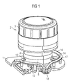
- the rotary actuator shown has a support plate 1, on which a cylinder-like handle 2 is rotatably mounted about its longitudinal axis.
- the handle 2 has at its end remote from the support plate 1 a button part 3, by means of which it can be rotated by a person about its longitudinal axis in twenty-four steps of rotation.
- the handle 2 At its end region facing the carrier plate 1, the handle 2 has, axially next to one another, a first coding ring 4 and a second coding ring 5.
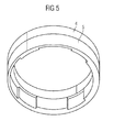
- the two coding rings 4 and 5 are made of a transparent material.
- the second coding ring 5 has three different radial thicknesses, resulting in three different degrees of radial transparency.
- the coding ring 5 has along its circumference three identical annular regions 6, 7 and 8, of which each annular region 6, 7 and 8 is in turn divided along its circumference into eight identical coding regions 6 ', 7' and 8 '.
- Each coding region 6 ', 7' and 8 ' corresponds to a rotation step of the handle 2 of 15 °.
- the light sources 9, 10 and 11 are radially opposite on the outside of the second Kodierrings 5 with their Lichteinkoppelstellen 12, 13 and 14 the light sources 9, 10 and 11 facing light guides 15, 16 and 17 are arranged, which are also attached to the support plate 1 and all lead to a single photosensor 18.
- the light guides 15, 16 and 17 form a single component.
- the light intensity of the light emitted by the light sources 9 to 11 reaching the light coupling points 12 to 14 is reduced to three different light intensities.
- the "0” stands for a low received light intensity
- "1” for a mean received light intensity
- "2" for a high received light intensity
- the received light intensity changes only at one of the three light coupling points 12 to 14.
- the control of the light sources 9 to 11 takes place in multiplex mode, wherein the photosensor 18 detects the light intensity and generates a corresponding light intensity signal and forwards to a not shown electronics in the same rhythm.
- the signal pattern table 19 is stored in a memory of the electronics.
- the rotary step position 22 can be defined.
- the electronics recognize that this pattern does not correspond to one of the signal patterns 21 of the signal pattern table 19 and therefore generates a special control signal for driving an electrical device (not shown).
Landscapes
- Physics & Mathematics (AREA)
- General Physics & Mathematics (AREA)
- Optical Transform (AREA)
Applications Claiming Priority (1)
| Application Number | Priority Date | Filing Date | Title |
|---|---|---|---|
| DE102008017069A DE102008017069A1 (de) | 2008-04-03 | 2008-04-03 | Drehsteller |
Publications (2)
| Publication Number | Publication Date |
|---|---|
| EP2107344A2 true EP2107344A2 (fr) | 2009-10-07 |
| EP2107344A3 EP2107344A3 (fr) | 2014-06-11 |
Family
ID=40783823
Family Applications (1)
| Application Number | Title | Priority Date | Filing Date |
|---|---|---|---|
| EP09100214.7A Withdrawn EP2107344A3 (fr) | 2008-04-03 | 2009-03-31 | Actuateur rotatif |
Country Status (2)
| Country | Link |
|---|---|
| EP (1) | EP2107344A3 (fr) |
| DE (1) | DE102008017069A1 (fr) |
Families Citing this family (2)
| Publication number | Priority date | Publication date | Assignee | Title |
|---|---|---|---|---|
| DE102013222350B4 (de) * | 2013-11-04 | 2024-07-25 | BHTC GmbH | Drehsteller für eine Fahrzeugkomponente |
| DE102016122585B4 (de) | 2016-11-23 | 2018-07-12 | Preh Gmbh | Drehsteller mit verbesserter, optischer Drehstellungsdetektion |
Family Cites Families (5)
| Publication number | Priority date | Publication date | Assignee | Title |
|---|---|---|---|---|
| US5237391A (en) * | 1988-11-23 | 1993-08-17 | The Boeing Company | Multitrack multilevel sensing system |
| DE19506019C2 (de) * | 1995-02-22 | 2000-04-13 | Telefunken Microelectron | Verfahren zum Betrieb eines optischen Lenkwinkelsensors |
| DE19758104B4 (de) * | 1997-02-13 | 2010-04-15 | Takata-Petri Ag | Adaptiver absoluter Lenkwinkelsensor |
| US6974949B2 (en) * | 2003-12-18 | 2005-12-13 | Illinois Tool Works Inc. | Position sensor with an optical member of varying thickness |
| DE102004020827A1 (de) * | 2004-04-28 | 2005-11-24 | Preh Gmbh | Drehsteller |
-
2008
- 2008-04-03 DE DE102008017069A patent/DE102008017069A1/de not_active Ceased
-
2009
- 2009-03-31 EP EP09100214.7A patent/EP2107344A3/fr not_active Withdrawn
Also Published As
| Publication number | Publication date |
|---|---|
| DE102008017069A1 (de) | 2009-10-22 |
| EP2107344A3 (fr) | 2014-06-11 |
Similar Documents
| Publication | Publication Date | Title |
|---|---|---|
| DE102015210657B4 (de) | Verfahren zur Erkennung einer Stellbewegung eines auf einer Anzeigefläche befindlichen Stellelementes in einem Kraftfahrzeug und Vorrichtung zur Durchführung des Verfahrens | |
| EP3645440B1 (fr) | Système de détermination de position et procédé de transmission d'une position de cabine d'un ascenseur | |
| WO2005068962A1 (fr) | Dispositif pour determiner un angle de braquage et un couple de rotation exerce sur un arbre de direction | |
| DE102006019449A1 (de) | Verfahren und Vorrichtung zur Identifizierung von Wechselobjektiven | |
| EP0953494A2 (fr) | Appareil pour détecter une valeur de torsion entre deux pièces | |
| DE19712869A1 (de) | Lenkwinkelsensorsystem mit erhöhter Redundanz | |
| EP2622311A1 (fr) | Résolveur capacitif | |
| EP0862728A1 (fr) | Capteur d'angle de rotation a ligne de ccd offrant une precision de mesure accrue | |
| WO2012028500A1 (fr) | Actionneur rotatif | |
| EP2107344A2 (fr) | Actuateur rotatif | |
| DE3243956A1 (de) | Positionsgeber zur lagebestimmung linear verfahrbarer maschinenteile | |
| EP1740910B1 (fr) | Actionneur rotatif | |
| DE102011109269B3 (de) | Stellungsmeldeanordnung | |
| EP1754956B1 (fr) | Capteur rotatif et système de réglage de véhicule automobile | |
| EP1476329B1 (fr) | Dispositif de direction comprennant de transmission de donnees sans contact entre volant et partie fixe | |
| EP2345054B1 (fr) | Module de commutation muni de moyens de detection pour l' identification de positions de commutation | |
| EP1770372B1 (fr) | Dispositif de mesure de position | |
| EP1770375B1 (fr) | Dispositif de mesure de position comprenant deux echelles de mesure dont les pistes codées se chevauchent mutuellement | |
| DE102005055307A1 (de) | Drehsteller mit inkrementellem Drehwinkelgeber | |
| EP3179217B1 (fr) | Dispositif de transmission sans contact de donnees et destiné à déterminer la modification angulaire entre deux objets se deplaçant l'un par rapport à l'autre | |
| DE102023134634B3 (de) | Vorrichtung und verfahren zur positions-, längen- oder winkelbestimmung | |
| EP0385386A2 (fr) | Méthode et dispositif pour la mesure d'un angle de rotation | |
| DE19936246A1 (de) | Lenkwinkelsensor | |
| EP1679565B1 (fr) | Système de contrôle pour une commande de porte | |
| DE4108954C2 (de) | Optischer Drehwinkelgeber |
Legal Events
| Date | Code | Title | Description |
|---|---|---|---|
| PUAI | Public reference made under article 153(3) epc to a published international application that has entered the european phase |
Free format text: ORIGINAL CODE: 0009012 |
|
| AK | Designated contracting states |
Kind code of ref document: A2 Designated state(s): AT BE BG CH CY CZ DE DK EE ES FI FR GB GR HR HU IE IS IT LI LT LU LV MC MK MT NL NO PL PT RO SE SI SK TR |
|
| AX | Request for extension of the european patent |
Extension state: AL BA RS |
|
| PUAL | Search report despatched |
Free format text: ORIGINAL CODE: 0009013 |
|
| AK | Designated contracting states |
Kind code of ref document: A3 Designated state(s): AT BE BG CH CY CZ DE DK EE ES FI FR GB GR HR HU IE IS IT LI LT LU LV MC MK MT NL NO PL PT RO SE SI SK TR |
|
| AX | Request for extension of the european patent |
Extension state: AL BA RS |
|
| RIC1 | Information provided on ipc code assigned before grant |
Ipc: G01D 5/347 20060101AFI20140505BHEP |
|
| AKY | No designation fees paid | ||
| AXX | Extension fees paid |
Extension state: AL Extension state: BA Extension state: RS |
|
| REG | Reference to a national code |
Ref country code: DE Ref legal event code: R108 |
|
| REG | Reference to a national code |
Ref country code: DE Ref legal event code: R108 Effective date: 20150218 |
|
| STAA | Information on the status of an ep patent application or granted ep patent |
Free format text: STATUS: THE APPLICATION IS DEEMED TO BE WITHDRAWN |
|
| 18D | Application deemed to be withdrawn |
Effective date: 20141212 |