EP2107348A2 - Débitmètre de type thermique - Google Patents
Débitmètre de type thermique Download PDFInfo
- Publication number
- EP2107348A2 EP2107348A2 EP09001027A EP09001027A EP2107348A2 EP 2107348 A2 EP2107348 A2 EP 2107348A2 EP 09001027 A EP09001027 A EP 09001027A EP 09001027 A EP09001027 A EP 09001027A EP 2107348 A2 EP2107348 A2 EP 2107348A2
- Authority
- EP
- European Patent Office
- Prior art keywords
- measuring element
- parts
- plate parts
- cantilever plate
- support member
- Prior art date
- Legal status (The legal status is an assumption and is not a legal conclusion. Google has not performed a legal analysis and makes no representation as to the accuracy of the status listed.)
- Granted
Links
- 239000000758 substrate Substances 0.000 claims abstract description 9
- 239000012530 fluid Substances 0.000 claims description 18
- 238000011144 upstream manufacturing Methods 0.000 claims description 16
- XLYOFNOQVPJJNP-UHFFFAOYSA-N water Substances O XLYOFNOQVPJJNP-UHFFFAOYSA-N 0.000 description 36
- 238000010276 construction Methods 0.000 description 8
- 239000010408 film Substances 0.000 description 5
- 238000009413 insulation Methods 0.000 description 5
- 239000004065 semiconductor Substances 0.000 description 5
- 239000010409 thin film Substances 0.000 description 5
- 238000002485 combustion reaction Methods 0.000 description 4
- 238000005516 engineering process Methods 0.000 description 4
- 238000004519 manufacturing process Methods 0.000 description 4
- 239000000853 adhesive Substances 0.000 description 3
- 230000001070 adhesive effect Effects 0.000 description 3
- 230000003247 decreasing effect Effects 0.000 description 3
- 230000000694 effects Effects 0.000 description 3
- 239000000463 material Substances 0.000 description 3
- 238000007493 shaping process Methods 0.000 description 3
- XUIMIQQOPSSXEZ-UHFFFAOYSA-N Silicon Chemical compound [Si] XUIMIQQOPSSXEZ-UHFFFAOYSA-N 0.000 description 2
- 229910052782 aluminium Inorganic materials 0.000 description 2
- 230000001815 facial effect Effects 0.000 description 2
- 239000007788 liquid Substances 0.000 description 2
- 238000005259 measurement Methods 0.000 description 2
- BASFCYQUMIYNBI-UHFFFAOYSA-N platinum Chemical compound [Pt] BASFCYQUMIYNBI-UHFFFAOYSA-N 0.000 description 2
- 229910052710 silicon Inorganic materials 0.000 description 2
- 239000010703 silicon Substances 0.000 description 2
- 239000013464 silicone adhesive Substances 0.000 description 2
- 239000004593 Epoxy Substances 0.000 description 1
- ZOKXTWBITQBERF-UHFFFAOYSA-N Molybdenum Chemical compound [Mo] ZOKXTWBITQBERF-UHFFFAOYSA-N 0.000 description 1
- 229910000990 Ni alloy Inorganic materials 0.000 description 1
- XAGFODPZIPBFFR-UHFFFAOYSA-N aluminium Chemical compound [Al] XAGFODPZIPBFFR-UHFFFAOYSA-N 0.000 description 1
- 239000000919 ceramic Substances 0.000 description 1
- 238000011109 contamination Methods 0.000 description 1
- 230000005611 electricity Effects 0.000 description 1
- 238000000605 extraction Methods 0.000 description 1
- 238000010438 heat treatment Methods 0.000 description 1
- 239000012535 impurity Substances 0.000 description 1
- 239000007769 metal material Substances 0.000 description 1
- 238000000034 method Methods 0.000 description 1
- 238000012986 modification Methods 0.000 description 1
- 230000004048 modification Effects 0.000 description 1
- 229910052750 molybdenum Inorganic materials 0.000 description 1
- 239000011733 molybdenum Substances 0.000 description 1
- 229910021421 monocrystalline silicon Inorganic materials 0.000 description 1
- 229910052697 platinum Inorganic materials 0.000 description 1
- 229910021420 polycrystalline silicon Inorganic materials 0.000 description 1
- 239000011347 resin Substances 0.000 description 1
- 229920005989 resin Polymers 0.000 description 1
- 239000000565 sealant Substances 0.000 description 1
- WFKWXMTUELFFGS-UHFFFAOYSA-N tungsten Chemical compound [W] WFKWXMTUELFFGS-UHFFFAOYSA-N 0.000 description 1
- 229910052721 tungsten Inorganic materials 0.000 description 1
- 239000010937 tungsten Substances 0.000 description 1
Images





Classifications
-
- G—PHYSICS
- G01—MEASURING; TESTING
- G01F—MEASURING VOLUME, VOLUME FLOW, MASS FLOW OR LIQUID LEVEL; METERING BY VOLUME
- G01F1/00—Measuring the volume flow or mass flow of fluid or fluent solid material wherein the fluid passes through a meter in a continuous flow
- G01F1/68—Measuring the volume flow or mass flow of fluid or fluent solid material wherein the fluid passes through a meter in a continuous flow by using thermal effects
- G01F1/684—Structural arrangements; Mounting of elements, e.g. in relation to fluid flow
- G01F1/6845—Micromachined devices
-
- G—PHYSICS
- G01—MEASURING; TESTING
- G01F—MEASURING VOLUME, VOLUME FLOW, MASS FLOW OR LIQUID LEVEL; METERING BY VOLUME
- G01F1/00—Measuring the volume flow or mass flow of fluid or fluent solid material wherein the fluid passes through a meter in a continuous flow
- G01F1/68—Measuring the volume flow or mass flow of fluid or fluent solid material wherein the fluid passes through a meter in a continuous flow by using thermal effects
- G01F1/684—Structural arrangements; Mounting of elements, e.g. in relation to fluid flow
- G01F1/6842—Structural arrangements; Mounting of elements, e.g. in relation to fluid flow with means for influencing the fluid flow
-
- G—PHYSICS
- G01—MEASURING; TESTING
- G01F—MEASURING VOLUME, VOLUME FLOW, MASS FLOW OR LIQUID LEVEL; METERING BY VOLUME
- G01F1/00—Measuring the volume flow or mass flow of fluid or fluent solid material wherein the fluid passes through a meter in a continuous flow
- G01F1/68—Measuring the volume flow or mass flow of fluid or fluent solid material wherein the fluid passes through a meter in a continuous flow by using thermal effects
- G01F1/684—Structural arrangements; Mounting of elements, e.g. in relation to fluid flow
- G01F1/688—Structural arrangements; Mounting of elements, e.g. in relation to fluid flow using a particular type of heating, cooling or sensing element
-
- G—PHYSICS
- G01—MEASURING; TESTING
- G01F—MEASURING VOLUME, VOLUME FLOW, MASS FLOW OR LIQUID LEVEL; METERING BY VOLUME
- G01F1/00—Measuring the volume flow or mass flow of fluid or fluent solid material wherein the fluid passes through a meter in a continuous flow
- G01F1/68—Measuring the volume flow or mass flow of fluid or fluent solid material wherein the fluid passes through a meter in a continuous flow by using thermal effects
- G01F1/684—Structural arrangements; Mounting of elements, e.g. in relation to fluid flow
- G01F1/688—Structural arrangements; Mounting of elements, e.g. in relation to fluid flow using a particular type of heating, cooling or sensing element
- G01F1/69—Structural arrangements; Mounting of elements, e.g. in relation to fluid flow using a particular type of heating, cooling or sensing element of resistive type
- G01F1/692—Thin-film arrangements
-
- G—PHYSICS
- G01—MEASURING; TESTING
- G01F—MEASURING VOLUME, VOLUME FLOW, MASS FLOW OR LIQUID LEVEL; METERING BY VOLUME
- G01F1/00—Measuring the volume flow or mass flow of fluid or fluent solid material wherein the fluid passes through a meter in a continuous flow
- G01F1/68—Measuring the volume flow or mass flow of fluid or fluent solid material wherein the fluid passes through a meter in a continuous flow by using thermal effects
- G01F1/696—Circuits therefor, e.g. constant-current flow meters
-
- G—PHYSICS
- G01—MEASURING; TESTING
- G01F—MEASURING VOLUME, VOLUME FLOW, MASS FLOW OR LIQUID LEVEL; METERING BY VOLUME
- G01F5/00—Measuring a proportion of the volume flow
Definitions
- the present invention relates to a thermal type flowmeter for measuring flow rate with a heat-generating resistor being arranged in the fluid to be measured, more specifically, relates to measurement of the intake air flow rate and the exhaust gas flow rate of an internal combustion engine of an automobile.
- a thermal type air flow rate sensor capable of direct measuring of mass flow amounts has been mainly in use.
- a sensor element of a thermal type flowmeter is manufactured using micro machine technology on a semiconductor substrate such as silicon (Si)
- a thermal type flowmeter of a semiconductor type a heat generating resisting body is shaped in a thin film part of several microns shaped in the semiconductor substrate. As it is a thin film, the heat capacity is small, and a quick response and low power consumption are possible. Further, it is easy to shape construction by micro-fabrication to detect the temperature difference of the down-stream and the up-stream of the heat generating resisting body and to judge following current / reverse current.
- Patent Document 1 The Japanese Unexamined Patent Publication No. 2000-146652
- water droplets mixed in the intake air are attached to a flow rate detecting element and measuring error occurs.
- the thermal type flowmeter of a semiconductor type because the detecting part is of a thin film, the heat capacity is small, therefore, if the water droplets are attached to the heat generating part, the temperature of a thin film part lowers sharply, and measuring of the flow rate may become impossible. Further, by attachment of the water droplets, the thin film part is cooled rapidly and the measuring element may possibly be destroyed.
- flow rectifying blades are shaped integrally with a sensor element. If the water droplets fly in to the thermal type flowmeter of such construction, the water droplets are trapped by the rectifying blades once, crawl along the side face of a flow rectifying member by the wind pressure, and thereafter, may possibly separate from the flow rectifying blades and attach to the resistance body shaped region of the measuring element. In the conventional technology, the problem on attachment of water droplets has been left.
- the present invention has been developed under consideration of the points described above, and is to provide a thermal type flowmeter wherein attachment of the water droplets and liquid fouling matter which have flied in to the measuring element is prevented.
- the thermal type flowmeter wherein a flow rate is measured by arranging the measuring element with an exothermic resistor and a temperature measuring resistor being shaped on its surface side is arranged within the fluid passage, cantilever plate parts protruding from a wall face of the fluid passage opposing to the surface of the measuring element toward the measuring element side are arranged, and/or the cantilever plate parts are extended from the upper stream to the down stream of the measuring element.
- the wall face opposing to the surface of the measuring element is to support the cantilever plate parts and may be constructed integrally with the wall face.
- the tip part of the cantilever plate parts (opposite side of the supporting part) may be apart from the measuring element by a predetermined distance to form a gap.
- the cantilever plate parts can be shaped by arranging in the plural in the direction of the face of the measuring element and the direction generally perpendicular to the axis of the fluid channel.
- the plate-like parts can constitute both-end supported plate parts supported by the wall face and the support member.
- the cantilever plate parts and the plate-like plate parts can form generally continuous faces.
- the plate thickness of the tip part of the cantilever plate parts can be shaped thinner than the plate thickness of the roots.
- the interval from the tip part of the cantilever plate parts to the measuring element is made G and the interval between the tip parts of a plurality of the cantilever plate parts is made D, it is possible to have a portion wherein the relation between the interval G and the interval D becomes G > D.
- the fluid passage shapes a sub-passage to which a portion of the fluid of the main passage where the fluid to be measured flows is taken, that a straight part where the channel is straight and, in the upper stream and the down stream of the straight part, curved parts where the channel is curved are provided within the sub-passage, and that the measuring element is arranged in the straight part.
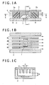
- FIG. 1 (a) is a cross-sectional view of the section where a measuring element 1 is arranged.
- FIG. 1 (b) is a cross-sectional view at X-X line in FIG. 1 (a)
- FIG. 1 (c) is a cross-sectional view at Y-Y line in FIG. 1 (a) .
- the measuring element 1 is arranged in a groove of a rectangular shape formed in a support member 2. Further, facing the support member 2, a facing wall 3 is shaped. Air flow 4, the object of measuring, flows between these support member 2 and the facing wall 3.
- cantilever plate parts 5 protruding from the facing wall 3 are shaped.
- a gap 6 is arranged between the tip part of the cantilever plate parts 5 and the measuring element 1.
- the facing wall 3 and the cantilever plate parts 5 are integrally formed by a resin such as PBT, the manufacturing process can be simplified.
- the cantilever plate parts 5 are extended from the upstream side end to the downstream side end of the measuring element 1.
- the cantilever plate parts 5 are disposed in the plural in the direction perpendicular to the flowing direction of the air flow 4.
- the gap between the tip part of the cantilever plate parts 5 and the surface of the measuring element 1 is made G and the interval for disposing the cantilever plate parts 5 in parallel is made D, it is preferable to become G > D.
- the value of G is approximately 1 mm, and if it is made smaller than this, water droplets are attached so as to bridge between the tip part of the cantilever plate parts 5 and the surface of the measuring element 1.
- both-end supported plate parts 7a protruding from the facing wall 3 are formed.
- This both-end supported plate parts 7a constitute plate-like parts extended beyond the tip part of the cantilever plate parts 5 to the measuring element 1 side. If the portion of the both-end supported plate parts 7a is formed integrally with the facing wall 3, the manufacturing process can be simplified. In this case, the root parts of the both-end supported plate parts 7a become the facing wall 3, and the tip parts either contact the support member 2 or are adhered by an adhesive. Or alternatively, the both-end supported plate parts 7a and the support member 2 are integrally formed.
- both-end supported plate parts 7a become the support member 2, and the tip parts may be constructed so as to be made close to or adhered to by an adhesive the facing wall 3.
- the cantilever plate part 5 and the both-end supported plate part 7a can be integrally formed to make one continuous plate.
- both-end supported plate parts 7b are formed in the downstream side of the measuring element 1 as well. It is preferable that the both-end supported plate parts 7b are of symmetric construction of the both-end supported plate parts 7a with the measuring element 1 as a center.
- guide parts 8 are arranged in the side faces of the both-end supported plate parts 7a, 7b.
- the guide parts 8 are formed by shaping grooves in the side faces of the both-end supported plate parts 7a, 7b.
- the guide parts 8 are shaped so as to head toward the facing wall side as they go close to the measuring element 1.
- guide parts 8 are formed in the plural.
- the guide parts 8 can be formed in both sides of the both-end supported plate parts, but can be formed in one side only.
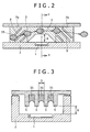
- FIG. 2 shows movement of the water droplets when the water droplets fly in from the upstream side in the present embodiment.
- the water droplet 35 flies in from the upper stream, it collides and attaches with the both-end supported plate parts 7a in the upstream side.
- the droplet attached crawls along the side face of the both-end supported plate parts 7a and moves to the downstream side.
- the guide parts 8 shaped in the side faces of the both-end supported plate parts 7a the water droplet heads for the side of the wall facing the measuring element 1.
- the droplet crawls along the side faces of the cantilever plate parts 5 and moves to the both-end supported plate parts 7b in the downstream side.
- the droplet is captured by the both-end supported plate parts 7a, 7b and the cantilever plate parts 5, and moves to the downstream side so as to avoid attachment to the measuring element 1.
- FIG. 3 shows a cross-sectional view at Y-Y line in FIG. 2 .
- the flowmeter is configured so that the relation between the interval D of the cantilever plate parts 5 and the gap G becomes D ⁇ G. With such configuration, the force of pulling water in of the gap G part is larger than that of D of the cantilever plate parts 5, and attachment to the measuring element 1 can be decreased more.
- the cantilever plate part 5 and the both-end supported plate parts 7a, 7b are made one continuous plate, however, the cantilever plate part 5 and the both-end supported plate parts 7a, 7b can be shaped so that they are separate and the side faces of these plates become a generally continuous face. Also, although the both-end supported plate parts 7a, 7b are of the shape fixed to both wall faces, they can be of the constitution wherein they are fixed to either one of the wall face and a minute gap exists against the other wall face.
- the guide parts 8 are of the shape of arranging a plurality of grooves in parallel, they can be in any shape as far as being shaped in the side faces of the both-end supported plate parts 7a, 7b and of a shape guiding the attached water droplets to the facing wall side.
- the guide parts 8 are shaped in the both-end supported plate parts 7a, 7b, they can be shaped in the side faces of the cantilever plate parts 5.
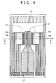
- FIG. 4 is a plan view showing the measuring element 1. Also, FIG. 5 shows a cross-sectional view along X-X line in FIG. 4 .
- a substrate 9 of the measuring element 1 is constituted of a material with excellent thermal conductivity ratio such as silicon and ceramic. Further, an insulation film 10 is formed on the substrate 9, and the substrate 9 is etched from the back side, thereby a diaphragm part 11 is shaped beneath the insulation film 10.
- an exothermic resistor 12 is formed on the surface of the insulation film 10 on the diaphragm part 11.
- the exothermic resistor 12 is heated so as to become hotter than the temperature of the air flow 4 by a prescribed temperature.
- temperature difference sensors 13a, 13b, 14a, 14b are formed in both sides of the exothermic resistor 12.
- the temperature difference sensors 13a, 13b are arranged in the upstream side of the exothermic resistor 12, and the temperature difference sensors 14a, 14b are arranged in the downstream side of the exothermic resistor 12.
- a heat sensitive resistor 15 whose resistance value changes according to the temperature of the air flow 4 is arranged. These resistors are protected by an insulation protection film 16.
- the exothermic resistor 12 it is preferable to form the exothermic resistor 12, the temperature difference sensors 13a, 13b, 14a, 14b, and the heat sensitive resistor 15 described above by a material with a comparatively large resistant temperature coefficient whose resistance value changes according to the temperature. Accordingly, they can be formed by a semiconductor material such as polycrystalline silicon and single-crystal silicon doped with impurities, and metallic materials such as platinum, molybdenum, tungsten, nickel alloy, and the like.
- an electrode pad 17 formed with aluminum or the like for taking out electrodes of the resistors described above and connecting to driving/detecting circuit is arranged.
- FIG. 5 cross-sectional construction of the measuring element 1 and the distribution of the surface temperature of the measuring element 1 are shown simultaneously.
- the continuous line shows the temperature distribution of the diaphragm part 11 at the time of no wind.
- the exothermic resistor 12 is heated so as to become hotter than the temperature of the air flow 4 by ⁇ Th.
- the dotted line of FIG. 5 is the temperature distribution of the diaphragm part 11 when the air flow 4 occurs.
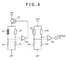
- FIG. 6 the driving / detecting circuit of the measuring element 1 is shown.
- a bridge circuit is constituted wherein a series circuit comprising the exothermic resistor 12 and a resistor 18 and a series circuit comprising the heat sensitive resistor 15 and a resistor 19 are connected in parallel.
- the differential voltage of the medium voltage of these series circuits is obtained and is connected to an amplifier 20.
- the output of the amplifier 20 is connected to the base of a transistor 21.
- the collector of the transistor 21 is connected to an electric source VB, and the emitter is connected between the exothermic resistor 12 and the heat sensitive resistor 15, thereby a feedback circuit is constituted.
- the circuit described above controls so that the resistance balance of the bridge circuit is maintained. If the resistance value of the heat sensitive resistor 15 increases by the temperature rise of the air flow 4, electric current flows simultaneously and heats the exothermic resistor 12. Thus, the resistance balance between the heat sensitive resistor 15 and the exothermic resistor 12 is maintained constant. In other words, the heating temperature of the exothermic resistor against the air flow temperature is maintained constant.
- a bridge circuit is constituted connecting in parallel a series circuit comprising the temperature difference sensor 13a and the temperature difference sensor 14a and a series circuit comprising the temperature difference sensor 14b and the temperature difference sensor 13b, and is connected to a reference voltage Vref.
- FIG. 7 the construction for attaching the measuring element 1 within an intake path of an internal combustion engine for an automobile and the like is shown in FIG. 7 .
- a base member 24 is arranged so as to protrude from the wall face of an intake path 23.
- a sub-passage 26 is shaped for taking in a portion of the air flow 25 within the intake path 23.
- the measuring element 1 is arranged in a rectangular recess shaped in the base member 24 within the sub-passage 26 .
- the channel of the sub-passage of the section where the measuring element 1 is arranged is straight, and its upstream side and downstream side are of a curved shape.
- a circuit substrate 27 mounting the driving circuit described above is arranged, and is electrically connected to the measuring element 1 by gold wire bonding wires 28. Further, terminals 29 and a connector 30 for electricity supply of the driving circuit and extraction of the output signal are arranged, and are connected to the driving circuit by aluminum bonding wires 31.
- FIG. 8 shows a cross-sectional view at Y-Y line in FIG. 7 .
- a cover member 32 is attached to the base member 24.
- the sub passage 26 is shaped so as to be sandwiched by the base member 24 and the cover member 32.
- the gold wire bonding wires 28 connecting the measuring element 1 and the driving circuit is protected by a sealant 33 such as epoxy.
- the cover member 32 and the base member 24 are adhered by a silicone adhesive and the like. Also, the cover member 32 and the circuit substrate 27 are adhered by the silicone adhesive to separate the air inside the sub-passage 26 for preventing leakage to the driving circuit side.
- the cantilever plate parts 5 described above are formed by shaping a plurality of projected plates in the section of the cover member 32 forming the sub-passage 26.
- the cantilever plate parts 5 are formed integrally with the cover member 32.
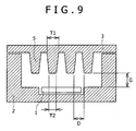
- FIG. 9 a cross-sectional view around the measuring element 1 in the present embodiment is shown.
- the cantilever plate parts 5 formed facing to the measuring element 1 is shaped so that the thickness of the tip part T2 is thinner than the thickness of the roots T1.
- the sectional shape of the cantilever plate parts 5 is in the shape of trapezoid, triangle, or the shape approximate thereto. With such shape, the effect of pulling more the water droplets attached between the cantilever plate parts 5 to the facing wall side by a capillary phenomenon is obtained. Consequently, attachment of the water droplets to the measuring element 1 can be decreased further.
- the relation of the interval D of the tip parts of a plurality of the cantilever plate parts 5 and the interval G between the cantilever plate parts 5 and the measuring element 1 becomes D ⁇ G. Further, with the shape described above, the mechanical strength of the cantilever plate parts 5 is enhanced.
- FIG. 10 (a) is a cross-sectional view of the section where the measuring element 1 is arranged.
- FIG. 10 (b) is a cross-sectional view at X-X line in FIG. 10 (a) .
- the cantilever plate parts 5 protruding from the facing wall 3 are formed facing the measuring element 1, and in the upper stream and down stream of the measuring element 1, cantilever plate parts 36a, 36b protruding from the support member 2 in the side the measuring element 1 is arranged are disposed.
- the cantilever plate parts 5 and the cantilever plate parts 36a, 36b are adjacent with each other, and the side faces of them form a generally continuous same face. Further, in the side faces of the cantilever plate parts 36a, 36b, the guide parts 8 are shaped.
- the water droplets attached to the cantilever plate parts 36a move to the facing wall side by the guide parts 8. Also, because the gaps between the cantilever plate parts 36a and the cantilever plate parts 5 are minute, the water droplets move to the cantilever plate parts 5. Further, the water droplets move to the cantilever plate parts 36b. Thus, even if the cantilever plate parts 5 and the cantilever plate parts 36a, 36b are separate, similar effect can be obtained by making them get close with each other.
- FIG. 11 (a) is a cross-sectional view of the section where the measuring element 1 is arranged.
- FIG. 11 (b) is a cross-sectional view at X-X line in FIG. 11 (a) .
- the cantilever plate parts 5 protruding from the facing wall 3 facing the measuring element 1 are arranged.
- both-end supported plate parts 37a, 37b supported by the support member 2 in the side where the measuring element 1 is arranged and the facing wall 3 are formed.
- the positional relation of the cantilever plate parts 5 and the both-end supported plate parts 37a, 37b will be described referring to FIG. 11 (b) .
- the cantilever plate parts 5 are arranged in the plural in the direction of the face of the measuring element 1 and in the direction perpendicular to the axis of the channel.
- the both-end supported plate parts 37a, 37b are also arranged in the plural in the same manner. Further, when viewed from Z direction in FIG. 11 (b) , the cantilever plate parts 5 and the both-end supported plate parts 37a are alternately disposed so that they have portions overlapping with each other. With respect to the both-end supported plate parts 37b, the same.
- the guide parts 8 are arranged in the side faces of the both-end supported plate parts 37a, 37b.
- the merit of the present embodiment will be described.
- the cantilever plate parts 5 and the both-end supported plate parts 37a, 37b are disposed alternately, the number of the plates shaped can be decreased.
- the forming process of the cantilever plate parts 5 and the both-end supported plate parts 37a, 37b is simplified.
- both-end supported plate parts 37a, 37b in the present embodiment are of the construction supported by the support member 2 and the facing wall 3, they may be of the cantilever plates protruding from the support member 2.
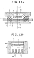
- FIG. 12 (a) is a cross-sectional view of the section where the measuring element 1 is arranged.
- FIG. 12 (b) is a cross-sectional view at X-X line in FIG. 12 (a) .
- the measuring element 1 is arranged in a rectangular recess shaped in the support member 2.
- the support member 2 is arranged so as to float off the inner wall of the passage where the fluid flows.
- the facing wall 3 is arranged so as to oppose to the face (surface) of the support member 2 where the measuring element 1 is disposed.
- a back side wall 38 is arranged in the back side of the support member 2.
- the channel diverged in the upstream side of the support member 2 is configured to join in the down stream of the support member 2.
- cantilever plate parts 41 protruding from the back side wall are arranged in the plural, and are extended from the upper stream of the branch point of the channel described above to the downstream side of the merging point of the channel described above.
- the cantilever plate parts 41 also in the upstream side of the branch point of the channel are shaped so as to be adjacent to or to be adhered to the facing wall 3.
- the cantilever plate parts 41 also in the downstream side of the merging point of the channel they are shaped so as to be adjacent to or to be adhered to the facing wall 3.
- the guide parts 8 heading to the back side wall 38 as they go close to the measuring element 1 are shaped. Furthermore, a gap is provided between the cantilever plate parts 41 and the support member 2.
- water droplets and liquid fouling matter flying in to the measuring element are trapped by plates shaped around the measuring element, crawl along the side faces of the plates so as to keep away from the measuring element and are made to flow to the down stream, thereby attaching to and contamination of the measuring element can be prevented, and highly accurate measurement of the flow rate becomes possible.
Landscapes
- Physics & Mathematics (AREA)
- Fluid Mechanics (AREA)
- General Physics & Mathematics (AREA)
- Measuring Volume Flow (AREA)
Applications Claiming Priority (1)
| Application Number | Priority Date | Filing Date | Title |
|---|---|---|---|
| JP2008089157A JP4576444B2 (ja) | 2008-03-31 | 2008-03-31 | 熱式流量計 |
Publications (3)
| Publication Number | Publication Date |
|---|---|
| EP2107348A2 true EP2107348A2 (fr) | 2009-10-07 |
| EP2107348A3 EP2107348A3 (fr) | 2014-03-26 |
| EP2107348B1 EP2107348B1 (fr) | 2017-10-18 |
Family
ID=40578923
Family Applications (1)
| Application Number | Title | Priority Date | Filing Date |
|---|---|---|---|
| EP09001027.3A Not-in-force EP2107348B1 (fr) | 2008-03-31 | 2009-01-26 | Débitmètre de type thermique |
Country Status (4)
| Country | Link |
|---|---|
| US (1) | US7647825B2 (fr) |
| EP (1) | EP2107348B1 (fr) |
| JP (1) | JP4576444B2 (fr) |
| CN (1) | CN101551261B (fr) |
Cited By (4)
| Publication number | Priority date | Publication date | Assignee | Title |
|---|---|---|---|---|
| WO2014063884A1 (fr) * | 2012-10-23 | 2014-05-01 | Continental Automotive Gmbh | Débitmètre massique d'air |
| EP3136062A1 (fr) * | 2011-01-31 | 2017-03-01 | Honeywell International Inc. | Ensemble de capteur de flux avec canal de dérivation intégré |
| CN107101685A (zh) * | 2011-12-07 | 2017-08-29 | 日立汽车系统株式会社 | 热式流量计 |
| EP2558840A4 (fr) * | 2010-04-14 | 2018-01-24 | Vasa Applied Technologies Ltd | Sonde pour débitmètre |
Families Citing this family (15)
| Publication number | Priority date | Publication date | Assignee | Title |
|---|---|---|---|---|
| US8534143B2 (en) * | 2009-10-02 | 2013-09-17 | Parker-Hannifin Corporation | Low-power force sensor |
| DE102010018947B4 (de) * | 2010-04-30 | 2022-11-17 | Abb Schweiz Ag | Thermischer Massendurchflussmesser mit metallgekapselter Sensorik |
| JP5462115B2 (ja) * | 2010-09-07 | 2014-04-02 | 日立オートモティブシステムズ株式会社 | 流体測定装置 |
| FR2977886B1 (fr) * | 2011-07-13 | 2017-03-03 | Centre Nat Rech Scient | Capteur miniaturise a element chauffant et procede de fabrication associe. |
| JP5632881B2 (ja) * | 2012-06-15 | 2014-11-26 | 日立オートモティブシステムズ株式会社 | 熱式流量計 |
| GB2510891A (en) | 2013-02-18 | 2014-08-20 | St Microelectronics Res & Dev | Apparatus |
| JP6126417B2 (ja) * | 2013-03-12 | 2017-05-10 | 日立オートモティブシステムズ株式会社 | 熱式流量計 |
| JP6129601B2 (ja) * | 2013-03-21 | 2017-05-17 | 日立オートモティブシステムズ株式会社 | 熱式流量計 |
| DE102013006670A1 (de) * | 2013-04-18 | 2014-10-23 | Hydrometer Gmbh | Durchflussmesser |
| JP6325679B2 (ja) | 2014-09-26 | 2018-05-16 | 日立オートモティブシステムズ株式会社 | 熱式流量計 |
| JP6395950B2 (ja) * | 2015-10-30 | 2018-09-26 | 日立オートモティブシステムズ株式会社 | 物理量検出装置 |
| DE112017004373T5 (de) * | 2016-11-30 | 2019-05-16 | Hitachi Automotive Systems, Ltd. | Messvorrichtung zur Bestimmung der Strömungsgeschwindigkeit von Luft |
| TWI683094B (zh) | 2017-06-01 | 2020-01-21 | 經登企業股份有限公司 | 感測器 |
| CN109029603B (zh) * | 2017-06-12 | 2020-10-16 | 经登企业股份有限公司 | 传感器 |
| US11280649B2 (en) * | 2019-10-21 | 2022-03-22 | Flusso Limited | Sensor assembly |
Citations (1)
| Publication number | Priority date | Publication date | Assignee | Title |
|---|---|---|---|---|
| JP2000146652A (ja) | 1998-11-05 | 2000-05-26 | Fuji Electric Co Ltd | マスフローセンサ |
Family Cites Families (9)
| Publication number | Priority date | Publication date | Assignee | Title |
|---|---|---|---|---|
| JP3716163B2 (ja) * | 2000-06-16 | 2005-11-16 | 株式会社日立製作所 | 空気流量測定装置 |
| JP3782669B2 (ja) * | 2001-02-28 | 2006-06-07 | 株式会社日立製作所 | 熱式流量測定装置 |
| DE10139933C2 (de) * | 2001-08-14 | 2003-10-30 | Siemens Ag | Massenstrommesser |
| JP2003315116A (ja) * | 2002-04-18 | 2003-11-06 | Denso Corp | 流量測定装置 |
| US6938473B2 (en) * | 2001-11-19 | 2005-09-06 | Denso Corporation | Apparatus for measuring flow amount |
| JP3753057B2 (ja) * | 2001-12-04 | 2006-03-08 | 株式会社日立製作所 | 気体流量測定装置 |
| JP3671399B2 (ja) * | 2002-09-20 | 2005-07-13 | 三菱電機株式会社 | 流量センサ |
| JP4161077B2 (ja) * | 2005-09-29 | 2008-10-08 | 三菱電機株式会社 | 流量測定装置 |
| JP2007248136A (ja) * | 2006-03-14 | 2007-09-27 | Hitachi Ltd | 熱式ガス流量測定装置 |
-
2008
- 2008-03-31 JP JP2008089157A patent/JP4576444B2/ja not_active Expired - Fee Related
- 2008-12-19 US US12/339,485 patent/US7647825B2/en not_active Expired - Fee Related
-
2009
- 2009-01-26 EP EP09001027.3A patent/EP2107348B1/fr not_active Not-in-force
- 2009-02-18 CN CN2009100064801A patent/CN101551261B/zh not_active Expired - Fee Related
Patent Citations (1)
| Publication number | Priority date | Publication date | Assignee | Title |
|---|---|---|---|---|
| JP2000146652A (ja) | 1998-11-05 | 2000-05-26 | Fuji Electric Co Ltd | マスフローセンサ |
Cited By (5)
| Publication number | Priority date | Publication date | Assignee | Title |
|---|---|---|---|---|
| EP2558840A4 (fr) * | 2010-04-14 | 2018-01-24 | Vasa Applied Technologies Ltd | Sonde pour débitmètre |
| EP3136062A1 (fr) * | 2011-01-31 | 2017-03-01 | Honeywell International Inc. | Ensemble de capteur de flux avec canal de dérivation intégré |
| CN107101685A (zh) * | 2011-12-07 | 2017-08-29 | 日立汽车系统株式会社 | 热式流量计 |
| WO2014063884A1 (fr) * | 2012-10-23 | 2014-05-01 | Continental Automotive Gmbh | Débitmètre massique d'air |
| US9664545B2 (en) | 2012-10-23 | 2017-05-30 | Continental Automotive Gmbh | Air mass sensor |
Also Published As
| Publication number | Publication date |
|---|---|
| US7647825B2 (en) | 2010-01-19 |
| EP2107348B1 (fr) | 2017-10-18 |
| US20090241660A1 (en) | 2009-10-01 |
| JP2009243996A (ja) | 2009-10-22 |
| CN101551261B (zh) | 2011-10-19 |
| EP2107348A3 (fr) | 2014-03-26 |
| JP4576444B2 (ja) | 2010-11-10 |
| CN101551261A (zh) | 2009-10-07 |
Similar Documents
| Publication | Publication Date | Title |
|---|---|---|
| US7647825B2 (en) | Thermal type flowmeter | |
| US9772208B2 (en) | Thermal type flowmeter with particle guide member | |
| JP5178598B2 (ja) | 熱式流量計 | |
| JP5683192B2 (ja) | 熱式流量センサ | |
| CN101308036B (zh) | 热式流量计 | |
| JP5315304B2 (ja) | 熱式流量計 | |
| JP3404300B2 (ja) | 感熱式流量センサ | |
| JP6043248B2 (ja) | 熱式空気流量計 | |
| EP2466275A1 (fr) | Pont de capteur avec ouvertures d'isolation thermique | |
| CN107949783B (zh) | 气体传感器装置 | |
| JP3920247B2 (ja) | 感熱式流量検出素子およびその製造方法 | |
| JP2008020193A (ja) | 熱式流量センサ | |
| JP3706358B2 (ja) | 気体流量・温度測定素子 | |
| EP2966417B1 (fr) | Dispositif de mesure d'écoulement d'air de type thermique | |
| JP5492834B2 (ja) | 熱式流量計 | |
| JP6674917B2 (ja) | 熱式流量計 |
Legal Events
| Date | Code | Title | Description |
|---|---|---|---|
| PUAI | Public reference made under article 153(3) epc to a published international application that has entered the european phase |
Free format text: ORIGINAL CODE: 0009012 |
|
| 17P | Request for examination filed |
Effective date: 20090703 |
|
| AK | Designated contracting states |
Kind code of ref document: A2 Designated state(s): AT BE BG CH CY CZ DE DK EE ES FI FR GB GR HR HU IE IS IT LI LT LU LV MC MK MT NL NO PL PT RO SE SI SK TR |
|
| AX | Request for extension of the european patent |
Extension state: AL BA RS |
|
| PUAL | Search report despatched |
Free format text: ORIGINAL CODE: 0009013 |
|
| AK | Designated contracting states |
Kind code of ref document: A3 Designated state(s): AT BE BG CH CY CZ DE DK EE ES FI FR GB GR HR HU IE IS IT LI LT LU LV MC MK MT NL NO PL PT RO SE SI SK TR |
|
| AX | Request for extension of the european patent |
Extension state: AL BA RS |
|
| RIC1 | Information provided on ipc code assigned before grant |
Ipc: G01F 1/688 20060101ALI20140217BHEP Ipc: G01F 1/684 20060101AFI20140217BHEP |
|
| AKX | Designation fees paid |
Designated state(s): DE FR GB IT |
|
| 17Q | First examination report despatched |
Effective date: 20160308 |
|
| REG | Reference to a national code |
Ref country code: DE Ref legal event code: R079 Ref document number: 602009048881 Country of ref document: DE Free format text: PREVIOUS MAIN CLASS: G01F0001684000 Ipc: G01F0001692000 |
|
| GRAP | Despatch of communication of intention to grant a patent |
Free format text: ORIGINAL CODE: EPIDOSNIGR1 |
|
| STAA | Information on the status of an ep patent application or granted ep patent |
Free format text: STATUS: GRANT OF PATENT IS INTENDED |
|
| RIC1 | Information provided on ipc code assigned before grant |
Ipc: G01F 1/684 20060101ALI20170410BHEP Ipc: G01F 5/00 20060101ALI20170410BHEP Ipc: G01F 1/688 20060101ALI20170410BHEP Ipc: G01F 1/696 20060101ALI20170410BHEP Ipc: G01F 1/692 20060101AFI20170410BHEP |
|
| INTG | Intention to grant announced |
Effective date: 20170426 |
|
| GRAS | Grant fee paid |
Free format text: ORIGINAL CODE: EPIDOSNIGR3 |
|
| GRAA | (expected) grant |
Free format text: ORIGINAL CODE: 0009210 |
|
| STAA | Information on the status of an ep patent application or granted ep patent |
Free format text: STATUS: THE PATENT HAS BEEN GRANTED |
|
| AK | Designated contracting states |
Kind code of ref document: B1 Designated state(s): DE FR GB IT |
|
| REG | Reference to a national code |
Ref country code: GB Ref legal event code: FG4D |
|
| RIN1 | Information on inventor provided before grant (corrected) |
Inventor name: HANZAWA, KEIJI Inventor name: NAKANO, HIROSHI Inventor name: MATSUMOTO, MASAHIRO |
|
| REG | Reference to a national code |
Ref country code: DE Ref legal event code: R096 Ref document number: 602009048881 Country of ref document: DE |
|
| REG | Reference to a national code |
Ref country code: DE Ref legal event code: R097 Ref document number: 602009048881 Country of ref document: DE |
|
| PLBE | No opposition filed within time limit |
Free format text: ORIGINAL CODE: 0009261 |
|
| STAA | Information on the status of an ep patent application or granted ep patent |
Free format text: STATUS: NO OPPOSITION FILED WITHIN TIME LIMIT |
|
| PG25 | Lapsed in a contracting state [announced via postgrant information from national office to epo] |
Ref country code: IT Free format text: LAPSE BECAUSE OF FAILURE TO SUBMIT A TRANSLATION OF THE DESCRIPTION OR TO PAY THE FEE WITHIN THE PRESCRIBED TIME-LIMIT Effective date: 20171018 |
|
| 26N | No opposition filed |
Effective date: 20180719 |
|
| GBPC | Gb: european patent ceased through non-payment of renewal fee |
Effective date: 20180126 |
|
| PG25 | Lapsed in a contracting state [announced via postgrant information from national office to epo] |
Ref country code: FR Free format text: LAPSE BECAUSE OF NON-PAYMENT OF DUE FEES Effective date: 20180131 |
|
| REG | Reference to a national code |
Ref country code: FR Ref legal event code: ST Effective date: 20180928 |
|
| PG25 | Lapsed in a contracting state [announced via postgrant information from national office to epo] |
Ref country code: GB Free format text: LAPSE BECAUSE OF NON-PAYMENT OF DUE FEES Effective date: 20180126 |
|
| PGFP | Annual fee paid to national office [announced via postgrant information from national office to epo] |
Ref country code: DE Payment date: 20210112 Year of fee payment: 13 |
|
| REG | Reference to a national code |
Ref country code: DE Ref legal event code: R119 Ref document number: 602009048881 Country of ref document: DE |
|
| PG25 | Lapsed in a contracting state [announced via postgrant information from national office to epo] |
Ref country code: DE Free format text: LAPSE BECAUSE OF NON-PAYMENT OF DUE FEES Effective date: 20220802 |