EP2107349B1 - Luftströmungsmessgerät - Google Patents
Luftströmungsmessgerät Download PDFInfo
- Publication number
- EP2107349B1 EP2107349B1 EP09008977.2A EP09008977A EP2107349B1 EP 2107349 B1 EP2107349 B1 EP 2107349B1 EP 09008977 A EP09008977 A EP 09008977A EP 2107349 B1 EP2107349 B1 EP 2107349B1
- Authority
- EP
- European Patent Office
- Prior art keywords
- passage
- air flow
- sub
- housing
- flow measuring
- Prior art date
- Legal status (The legal status is an assumption and is not a legal conclusion. Google has not performed a legal analysis and makes no representation as to the accuracy of the status listed.)
- Expired - Lifetime
Links
Images


Classifications
-
- G—PHYSICS
- G01—MEASURING; TESTING
- G01F—MEASURING VOLUME, VOLUME FLOW, MASS FLOW OR LIQUID LEVEL; METERING BY VOLUME
- G01F1/00—Measuring the volume flow or mass flow of fluid or fluent solid material wherein the fluid passes through a meter in a continuous flow
- G01F1/68—Measuring the volume flow or mass flow of fluid or fluent solid material wherein the fluid passes through a meter in a continuous flow by using thermal effects
- G01F1/684—Structural arrangements; Mounting of elements, e.g. in relation to fluid flow
- G01F1/6845—Micromachined devices
-
- G—PHYSICS
- G01—MEASURING; TESTING
- G01F—MEASURING VOLUME, VOLUME FLOW, MASS FLOW OR LIQUID LEVEL; METERING BY VOLUME
- G01F1/00—Measuring the volume flow or mass flow of fluid or fluent solid material wherein the fluid passes through a meter in a continuous flow
- G01F1/68—Measuring the volume flow or mass flow of fluid or fluent solid material wherein the fluid passes through a meter in a continuous flow by using thermal effects
- G01F1/684—Structural arrangements; Mounting of elements, e.g. in relation to fluid flow
- G01F1/6842—Structural arrangements; Mounting of elements, e.g. in relation to fluid flow with means for influencing the fluid flow
-
- G—PHYSICS
- G01—MEASURING; TESTING
- G01F—MEASURING VOLUME, VOLUME FLOW, MASS FLOW OR LIQUID LEVEL; METERING BY VOLUME
- G01F15/00—Details of, or accessories for, apparatus of groups G01F1/00 - G01F13/00 insofar as such details or appliances are not adapted to particular types of such apparatus
- G01F15/12—Cleaning arrangements; Filters
-
- G—PHYSICS
- G01—MEASURING; TESTING
- G01F—MEASURING VOLUME, VOLUME FLOW, MASS FLOW OR LIQUID LEVEL; METERING BY VOLUME
- G01F5/00—Measuring a proportion of the volume flow
Definitions
- the present invention relates to air flow measuring devices, and particularly, to air flow measuring devices for internal combustion engines.
- Conventional air flow measuring devices for internal combustion devices are provided with a filter element for cleaning the incoming air.
- its cleaning effect is inadequate since the dust particles or moisture contained in the intake air, often passes through the filter element reaching the air intake passage, where the air flow measuring device is located.
- certain aftermarket air filter products are poorer in quality as compared to the original product which further exasperates the problem. If the dust particles contained in the intake air adheres to the flow measuring element of the air flow measuring device, the characteristic heat radiation which is utilized to accurately measure the air flow can deviate, outputting inaccurate results.
- the flow measuring element may even be damaged. Further, if moisture, such as water, adheres to the measuring element, the element may deteriorate with time due to sudden temperature changes or provide an inaccurate output due to changes in the heat radiation rate.
- the document DE 198 15 654 A1 discloses an air flow measuring device with a sub-passage having multiple paths and a vent. A flow measuring element is disposed in an intermediate area between the paths.
- An object of the present invention is to provide a sub-passage that allows dust or moisture contained in the intake air, which may provide inaccurate readings by an air flow measuring element, due to contamination or break-down, to be separated by inertial force of the dust or moisture while ensuring a sufficient air flow in the area where the flow measuring element is installed.
- the object is achieved with an air flow measuring device according to claim 1.
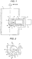
- Fig. 1 illustrates a cross-sectional view of an air flow measuring device.
- the air flow measuring device is preferably a heating resistor type.
- a module housing 2 for a heating resistor type air flow measuring device is installed through a module flange 5.
- a sub-passage 7 is formed at the end of the module housing 2 and a flow measuring element 3 is installed inside the sub-passage 7.
- the flow measuring element 3 is electrically connected with an electronic circuit 4 installed in the module housing 2 and the electronic circuit 4 is electrically connected with the outside through a connector 6.
- the sub-passage 7 contains a sub-passage inlet 9 whose opening face is perpendicular to the air flow into the air intake passage 1 and a sub-passage outlet 10 whose opening face is parallel to the air flow into the air intake passage 1.
- the direction of the air flow is in line with the inlet 9 and the air flow exits outlet 10 in a direction which is perpendicular to the entering air flow.
- Sub-passage 7 has a semicircular bottom bend 8 with a predefined curved surface and the flow measuring element 3 is located on the downstream side of the bend of the sub-passage 7.
- Bottom bend 8 has a maximum downstream point 8a (shown in Fig.
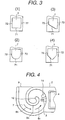
- Fig. 2 is a cross-sectional view of a sub-passage structure in another air flow measuring device.
- Sub-passage 7 has a predefined curvature which continues to curve to outlet 10 beyond the flow measuring element 3.
- the flow measuring element 3 is located in a direction downstream 8c from the maximum downstream point 8a relative to the air flow in the sub-passage 7 as described in Fig. 1 .
- the opening face of the sub-passage inlet 9 is perpendicular to the air flow into the air intake passage 1 and the sub-passage outlet 10 has its opening face in a plane parallel to the direction of the air flow.
- dust particles or other foreign matter which has entered the sub-passage 7 goes along the outer wall 71 (as shown in Fig.
- the sub-passage 7 is continuously curved to the outlet 10 so that vortex formation which may occur on the downstream side of the inner wall area of the sub-passage bend can be effectively suppressed, allowing the heating resistor type air flow measuring element 3 to provide a stable output with less noise.
- the position of the sub-passage outlet 10 can be altered without changing the size of the entire sub-passage, which means that the relative distance between the sub-passage inlet 9 and the sub-passage outlet 10 can be changed.
- the relative distance between the sub-passage inlet 9 and outlet 10 is an important factor that determines the effect of inertia given throughout the sub-passage 7. By changing the distance freely, the effect of the air flow in the air flow measuring device can be more easily controlled.
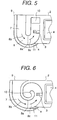
- Figs. 3-1 through 3-4 illustrate cross-sectional views of the sub-passage 7 shown in Figs. 1 and 2 , in particular, cross-section "A-A" of Fig.2 .
- foreign matter that has entered the sub-passage 7 collides against the outer wall surface 71 of the sub-passage 7.
- the outer wall surface 71 is completely flat and the foreign matter which has collided against the wall surface 71 may rebound toward the center of the sub-passage 7 again.
- outer wall 71 does not provide a means for guiding and gathering the dust particles or foreign matter. Rather, foreign matter repeatedly rebounds and collides against outer wall 71 while gradually moving along the outer wall surface 71 of the sub-passage 7 to outlet 10.
- Figs. 3-2 through 3-4 are grooved to effectively gather and guide foreign matter to outlet 10.
- Fig. 3-2 shows an example in which the outer wall surface 71 of the sub-passage is grooved to be semicircular.
- Fig. 3-3 shows an example in which one side of a junction between the sub-passage outer wall surface 71 and the sub-passage side wall surfaces 72 is grooved.
- Fig. 3-4 shows an example where both sides of the junction between the sub-passage outer wall surface 71 and the sub-passage side wall surfaces 72 are grooved.
- Fig. 4 illustrates a cross-sectional view of a modified version of the sub-passage structure as shown in Fig. 2 .
- an air vent 11 with an opening surface area of less than about fifty percent of the opening surface area of the sub-passage outlet 10 is provided on the sub-passage side wall surface 72, downstream 8c from the flow measuring element 3.
- the inertial effect of the sub-passage 7 can be effectively controlled.
- Another advantage of this structure is air vent 11 allows any water trapped in sub-passage 7 to be effectively forced out of it, even if the air in it is still.
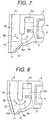
- Figs. 5 and 6 are cross-sectional views of another examples of the sub-passage structures as shown in Figs. 1 and 2 , respectively.
- an air vent 11 with a height "a" of about 1 mm is provided in a direction upstream 8b from the flow measuring element 3 in sub-passage 7.
- the ratio of the opening surface area of the air vent 11 to that of the sectional surface area (at its widest point) of sub-passage 7 is less than 1:10, it is possible to effectively discharge foreign matter as mentioned above, without impairing the performance of the sub-passage 7.
- an air vent 11 of this device is effective in eliminating moisture which may collect inside the sub-passage 7.
- Fig. 7 illustrates a cross-sectional view of a modified version of the sub-passage structure as shown in Fig. 1 .
- the sub-passage 7 has a sub-passage inlet 9 with an opening face which is perpendicular to the air flow in the air intake passage 1 and a sub-passage outlet 10 with an opening face parallel to the air flow in the air intake passage 1.
- Sub-passage 7 has a semi-circular bottom bend 8 with a predefined curved surface and the flow measuring element 3 is located on the downstream side of the bend of the sub-passage 7.
- Bottom bend 8 has a maximum downstream point 8a (shown in Fig. 7 ) at or near the apex of the curvature.
- first vertical path bottom inclination 12 with a given angle from the plane of air flow from the sub-passage inlet 9.
- an air vent 11 is provided at the base of the inclination 12.
- dust particles or other foreign matter which has entered the sub-passage 7 will tend to go straight down the first vertical path 73 by its own weight and velocity toward the first vertical path bottom inclination 12.
- the dust particles or other foreign matter exits sub-passage 7 by air vent 11. Therefore, air flow, free of debris or moisture can flow in the first horizontal path 75, then downstream towards the second vertical path 74 and exits at outlet 10.
- Fig. 8 illustrates a cross-sectional view of a modified version of the sub-passage structure as shown in Fig. 1 .
- a second vertical path bottom inclination 12a (shown in Fig. 8 ) is provided opposite to that of the first inclination 12.
- the second inclination 12a is also provided upstream from the maximum downstream point 8a.
- This design is suited to sub-passages which has a first vertical path 73, smaller than the one described in Fig. 7 .
- Figs. 9 and 10 show embodiments of the invention, as modified versions of the device shown in Fig. 7 .
- the air flow measuring element 3 is also provided downstream from the maximum downstream point 8a (shown in Fig. 9 and 10 ).
- a second horizontal path 76 is shown in the embodiment as described in Fig. 10 .
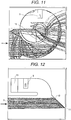
- Fig. 11 illustrates the result of Computer Aided Engineering (CAE) calculation which was carried out utilizing the air flow measuring device of Fig. 2 .
- the solid lines represent passage wall surfaces and the dotted lines represent tracks of dust particles or foreign matter in the air.
- the figure demonstrates that dust coming in through the sub-passage inlet 9 collides against the outer wall surface 71 of the sub-passage 7 and rebounds from it repeatedly, while gradually moving along the outer wall surface 71. In other words, dust particles or foreign matter is concentrated and guided near the outer wall surface 71 and exits outlet 10 with little influence on the measuring element 3.
- Fig. 12 illustrates the result of another CAE of the air flow measuring device according to Fig. 7 .
- the solid lines represent passage wall surfaces and the dotted lines represent tracks of dust in the air. Dust coming in through the sub-passage inlet 9 goes straight and collides against the first vertical path bottom inclination 12. Then the dust rebounds toward the air vent 11 due to the inclination angle and is forced out of the sub-passage 7. In other words, dust particles or foreign matter is concentrated and guided near the outer wall surface 71 and exits air vent 11 with little influence on the measuring element 3 while the air flow exits outlet 10.
- the present invention provides an air flow measuring device comprising a housing with a sub-passage having an inlet and an outlet for air flow formed in the housing.
- the sub-passage has a predefined curvature with a maximum downstream point.
- a flow measuring element is located in the sub-passage at a position at least further downstream from the point.
- Fig. 13 illustrates an example of an internal combustion engine 507 utilizing the air flow measuring device as described in Figs. 1-12 of the present invention.
- Air introduced into a combustion chamber 507c of the engine 507 is a combination of an air intake and EGR gas, wherein the air intake is let in by way of an inlet part 502a of an air cleaner 502 and passes through an air flow measuring device 503 of the present invention, which is one of the means for measuring the operating state of the engine 507.
- the air further passes through a throttle body 505 in which an electrically controlled throttle valve 505a for controlling the air intake flow quantity is housed.
- the electrically controlled throttle valve 505a is driven by an electrically controlled throttle motor 526.
- the air enters a collector 506.
- a signal representing the air intake flow quantity is outputted to a control unit 515, for example, a engine control unit.
- a throttle sensor 504 which detects the aperture of the electrically controlled throttle valve for measuring the operating state of the engine, is fitted to the throttle body 505 and its signal is also outputted to the control unit 515.
- a bypass pipe 525 is provided to constitute bypass piping for recirculating exhaust gas and bypass pipe 525 is provided with an electrically controlled type EGR valve 524, for controlling the recirculating flow quantity of exhaust gas.
- the fuel is subjected to another constant pressure by another fuel pressure regulator 513 and injected from injectors 509, one of which is provided for in each cylinder, into combustion chambers 507c.
- Fuel injected into combustion chambers 507c is raised in voltage by ignition coils 522 and ignited by ignition plugs 508 in response to an ignition signal.
- a crank angle sensor fitted to a crankshaft 507d of the engine 507 outputs an angle signal POS for detecting a revolution signal, indicating the rotational position of the crankshaft 507d, to the control unit 515.
- a catalytic converter 520 is provided midway on each exhaust pipe 519 and an A/F sensor 518 provided upstream from the catalytic converter 520 detects the contents of exhausted gas, the resultant detection signal being outputted to the control unit 515.
Landscapes
- Physics & Mathematics (AREA)
- Fluid Mechanics (AREA)
- General Physics & Mathematics (AREA)
- Measuring Volume Flow (AREA)
Claims (6)
- Luftströmungsmessvorrichtung zum Messen eines Luftstroms, der durch einen Ansaugdurchgang (1) eines Verbrennungsmotors strömt, durch Erfassung einer Luftströmung, die durch einen Teildurchgang (7) strömt, der in dem Ansaugdurchgang angeordnet ist, wobei die Luftströmung, die durch den Teildurchgang strömt, ein Teil der Luftströmung ist, die durch den Ansaugdurchgang strömt, wobei die Luftströmungsmessvorrichtung aufweist:ein Strömungsmesselement (3) zum Messen einer Luftströmung, undein Gehäuse (2), in dem der Teildurchgang ausgeformt ist, und wobei das Strömungsmesselement in dem Teildurchgang (7) angeordnet ist, wobei das Gehäuse einen Endbereich aufweist mit einem Flansch (5) zur Montage der Luftströmungsmessvorrichtung in dem Ansaugdurchgang (1), eine stromauf gelegene Seite und eine stromab gelegene Seite, die der stromauf gelegenen Seite gegenüberliegt,wobei der Teildurchgang (7) aufweist:einen Einlassbereich (9), der auf der stromauf gelegenen Seite des Gehäuses (2) vorgesehen ist und eine Öffnungsfläche aufweist, die senkrecht zu der Luftströmung in dem Ansaugdurchgang (1) orientiert ist,einen Auslassbereich (10),einen ersten vertikalen Pfad (73), dessen eines Ende mit dem Einlassbereich (9) in Verbindung steht, und wobei ein anderes Ende mit einem Schlitz (11) in Verbindung steht, der an dem stromab gelegenen Ende einer Schräge (12) vorgesehen ist, wobei ein Teil der Luft, die in dem Einlassbereich (9) eintritt auf dem ersten vertikalen Pfad (73) gerade herunter auf die Schräge (12) und den Schlitz (11) zu strömt, undeinen Verzweigungspfad (74, 75), der von dem ersten vertikalen Pfad (73) abzweigt und mit dem Auslassbereich (10) in Verbindung steht,wobei das Strömungsmesselement (3) in einem Zwischenbereich in dem Verzweigungspfad (74, 75) angeordnet ist,dadurch gekennzeichnet, dass der Verzweigungspfad in einem Bereich abzweigt, der stromauf zu der Schräge (12) gelegen ist, und dadurch, dass der Verzweigungspfad einen ersten horizontalen Pfad (75) aufweist, der von dem ersten vertikalen Pfad (73) zwischen dem Einlassbereich (9) und dem Schlitz (11) in Richtung auf den einen Endbereich des Gehäuses (2) mit dem Flansch (5) und einem zweiten vertikalen Pfad (74) abzweigt, der mit dem ersten horizontalen Pfad (75) an einem stromab gelegenen Ende des ersten horizontalen Pfads in Verbindung steht, sodass er den ersten horizontalen Pfad (75) mit dem Auslassbereich (10) verbindet, der auf der stromab gelegenen Seite des Gehäuses (2) gelegen ist,wobei der zweite vertikale Pfad (74) in einer Richtung von der stromauf gelegenen Seite des Gehäuses (2) zu der stromab gelegenen Seite des Gehäuses (2) der Luftströmung, die durch den Ansaugdurchgang (1) strömt, angeordnet ist, undwobei der Auslassbereich (10) eine Öffnungsfläche aufweist, die parallel zu der Luftströmung in dem Ansaugdurchgang (1) orientiert ist.
- Luftströmungsmessvorrichtung nach Anspruch 1, wobei der Verzweigungspfad ferner einen zweiten horizontalen Pfad (76) aufweist, der mit dem zweiten vertikalen Pfad in einem Bereich in Verbindung steht, der stromabwärts zu dem zweiten vertikalen Pfad gelegen ist, und sich zu dem anderen Endbereich des Gehäuses (2) erstreckt.
- Luftströmungsmessvorrichtung nach Anspruch 1, mit einem elektrischen Schaltkreis, der elektrisch mit dem Strömungsmesselement (3) verbunden ist.
- Luftströmungsmessvorrichtung nach Anspruch 3, wobei das Gehäuse (2) den elektrischen Schaltkreis aufweist.
- Luftströmungsmessvorrichtung nach den Ansprüchen 3 oder 4, mit:einem Flansch (5), der mit dem Gehäuse (2) an dem einen Endbereich des Gehäuses verbunden ist und außerhalb einer Wand angeordnet ist, die den Ansaugdurchgang (1) bildet,wobei das Gehäuse auf der Wand über dem Flansch (5) montiert ist, sodass ein anderer Endbereich des Gehäuses (2), der gegenüber dem einen Endbereich liegt, in den Ansaugdurchgang (1) hineinragt, undder Teildurchgang (7), der elektrische Schaltkreis und der Flansch (5), in der Reihenfolge: Teildurchgang (7), elektrischer Schaltkreis und Flansch, in einer Richtung von dem anderen Endbereich des Gehäuses zu dem einen Endbereich des Gehäuses (2) angeordnet sind.
- Luftströmungsmessvorrichtung nach den Ansprüchen 3 bis 5,wobei der Verzweigungspfad (74, 75) von dem ersten vertikalen Pfad (73) zu dem einen Endbereich des Gehäuses abzweigt, sodass ein Zwischenbereich des Verzweigungspfads sich von dem Einlassbereich weg erstreckt und dem elektrischen Schaltkreis in dem Gehäuse (2) nahekommt.
Applications Claiming Priority (2)
| Application Number | Priority Date | Filing Date | Title |
|---|---|---|---|
| JP2000185907A JP3716163B2 (ja) | 2000-06-16 | 2000-06-16 | 空気流量測定装置 |
| EP01113643.9A EP1164360B1 (de) | 2000-06-16 | 2001-06-18 | Luftströmungsmessgerät |
Related Parent Applications (2)
| Application Number | Title | Priority Date | Filing Date |
|---|---|---|---|
| EP01113643.9A Division EP1164360B1 (de) | 2000-06-16 | 2001-06-18 | Luftströmungsmessgerät |
| EP01113643.9A Division-Into EP1164360B1 (de) | 2000-06-16 | 2001-06-18 | Luftströmungsmessgerät |
Publications (2)
| Publication Number | Publication Date |
|---|---|
| EP2107349A1 EP2107349A1 (de) | 2009-10-07 |
| EP2107349B1 true EP2107349B1 (de) | 2017-09-13 |
Family
ID=18686157
Family Applications (3)
| Application Number | Title | Priority Date | Filing Date |
|---|---|---|---|
| EP09008977.2A Expired - Lifetime EP2107349B1 (de) | 2000-06-16 | 2001-06-18 | Luftströmungsmessgerät |
| EP10001415.8A Expired - Lifetime EP2187181B1 (de) | 2000-06-16 | 2001-06-18 | Luftströmungsmessgerät |
| EP01113643.9A Expired - Lifetime EP1164360B1 (de) | 2000-06-16 | 2001-06-18 | Luftströmungsmessgerät |
Family Applications After (2)
| Application Number | Title | Priority Date | Filing Date |
|---|---|---|---|
| EP10001415.8A Expired - Lifetime EP2187181B1 (de) | 2000-06-16 | 2001-06-18 | Luftströmungsmessgerät |
| EP01113643.9A Expired - Lifetime EP1164360B1 (de) | 2000-06-16 | 2001-06-18 | Luftströmungsmessgerät |
Country Status (3)
| Country | Link |
|---|---|
| US (5) | US7059183B2 (de) |
| EP (3) | EP2107349B1 (de) |
| JP (1) | JP3716163B2 (de) |
Families Citing this family (33)
| Publication number | Priority date | Publication date | Assignee | Title |
|---|---|---|---|---|
| JP3716163B2 (ja) * | 2000-06-16 | 2005-11-16 | 株式会社日立製作所 | 空気流量測定装置 |
| KR20020053301A (ko) * | 2000-12-27 | 2002-07-05 | 이계안 | 차량용 에어 플로우 센서 장착구조 |
| US7467546B2 (en) | 2001-07-18 | 2008-12-23 | Hitachi, Ltd. | Equipment for measuring gas flow rate |
| US7004022B2 (en) * | 2001-07-18 | 2006-02-28 | Hitachi, Ltd. | Equipment for measuring gas flow rate |
| JP3709385B2 (ja) * | 2002-07-01 | 2005-10-26 | 株式会社日立製作所 | 内燃機関用気体流量測定装置 |
| DE10230531B4 (de) * | 2002-07-05 | 2018-01-18 | Robert Bosch Gmbh | Vorrichtung zur Bestimmung wenigstens eines Parameters eines in einer Leitung strömenden Mediums |
| JP4073324B2 (ja) * | 2003-01-24 | 2008-04-09 | 株式会社日立製作所 | 熱式流量測定装置 |
| JP4534526B2 (ja) * | 2004-02-27 | 2010-09-01 | オムロン株式会社 | 流速測定装置 |
| JP4476287B2 (ja) * | 2004-06-10 | 2010-06-09 | 株式会社山武 | 流量計 |
| WO2006003717A1 (ja) * | 2004-06-30 | 2006-01-12 | Hitachi, Ltd. | 空気流量測定装置 |
| JP4512499B2 (ja) * | 2005-02-14 | 2010-07-28 | 日立オートモティブシステムズ株式会社 | 空気流量測定装置 |
| JP3832498B1 (ja) * | 2005-06-24 | 2006-10-11 | オムロン株式会社 | 流量測定装置 |
| JP4161077B2 (ja) * | 2005-09-29 | 2008-10-08 | 三菱電機株式会社 | 流量測定装置 |
| JP5085889B2 (ja) * | 2006-06-06 | 2012-11-28 | 日立オートモティブシステムズ株式会社 | 発熱抵抗体式流量測定装置 |
| JP4881676B2 (ja) * | 2006-08-30 | 2012-02-22 | 日立オートモティブシステムズ株式会社 | 熱式流量測定装置 |
| DE102006045656A1 (de) * | 2006-09-27 | 2008-04-03 | Robert Bosch Gmbh | Strömungsdynamisch verbesserter Steckfühler |
| DE102006045657A1 (de) * | 2006-09-27 | 2008-04-03 | Robert Bosch Gmbh | Steckfühler mit optimiertem Strömungsauslass |
| JP2008175150A (ja) * | 2007-01-19 | 2008-07-31 | Hitachi Ltd | 空気流量測定装置 |
| DE102007021025A1 (de) * | 2007-05-04 | 2008-11-06 | Continental Automotive Gmbh | Luftmassenmesser |
| JP4488030B2 (ja) * | 2007-06-14 | 2010-06-23 | 株式会社デンソー | 空気流量測定装置 |
| JP4576444B2 (ja) * | 2008-03-31 | 2010-11-10 | 日立オートモティブシステムズ株式会社 | 熱式流量計 |
| JP4968267B2 (ja) * | 2009-01-07 | 2012-07-04 | 株式会社デンソー | 空気流量測定装置 |
| DE102010020264A1 (de) * | 2010-05-28 | 2011-12-01 | Continental Automotive Gmbh | Luftmassenmesser |
| DE102011078004A1 (de) * | 2011-06-22 | 2012-12-27 | Robert Bosch Gmbh | Sensoranordnung zur Bestimmung wenigstens einer Strömungseigenschaft eines mit einer Hauptströmungsrichtung strömenden fluiden Mediums |
| JP5408195B2 (ja) * | 2011-07-19 | 2014-02-05 | 株式会社デンソー | 空気流量測定装置 |
| JP5675707B2 (ja) * | 2012-06-15 | 2015-02-25 | 日立オートモティブシステムズ株式会社 | 熱式流量計 |
| JP5791759B1 (ja) * | 2014-05-19 | 2015-10-07 | 三菱電機株式会社 | 流量測定装置 |
| JP6325679B2 (ja) * | 2014-09-26 | 2018-05-16 | 日立オートモティブシステムズ株式会社 | 熱式流量計 |
| JP6421104B2 (ja) * | 2015-09-25 | 2018-11-07 | 日立オートモティブシステムズ株式会社 | 主空気通路構成部材 |
| JP6690403B2 (ja) | 2016-05-24 | 2020-04-28 | 株式会社デンソー | 空気流量測定装置 |
| DE102016120303B4 (de) * | 2016-10-25 | 2021-11-11 | Endress+Hauser Flowtec Ag | Magnetisch-induktives Durchflussmessgerät zur Detektion von Fremdkörpern in einem ein Messrohr durchströmendes Medium |
| JP6289585B1 (ja) * | 2016-10-25 | 2018-03-07 | 三菱電機株式会社 | 流量測定装置 |
| JP7068103B2 (ja) * | 2018-08-24 | 2022-05-16 | 株式会社Soken | 流量測定装置 |
Family Cites Families (17)
| Publication number | Priority date | Publication date | Assignee | Title |
|---|---|---|---|---|
| JPS5653411A (en) | 1979-10-08 | 1981-05-13 | Hitachi Ltd | Hot wire type air flow meter |
| JPS5826221A (ja) * | 1981-08-10 | 1983-02-16 | Hitachi Ltd | 内燃機関の空気流量測定装置 |
| JPS6165053A (ja) * | 1984-09-07 | 1986-04-03 | Hitachi Ltd | 空気流量計 |
| US5127173A (en) * | 1990-10-12 | 1992-07-07 | Allied-Signal Inc. | Volumetric fluid flowmeter and method |
| US5355726A (en) * | 1994-01-03 | 1994-10-18 | Ford Motor Company | Housing for reducing back air flow to mass air flow sensors |
| US5537870A (en) * | 1994-10-03 | 1996-07-23 | Ford Motor Company | Contaminant free backflow reducing insert for mass air flow sensors |
| JP3193837B2 (ja) * | 1994-10-18 | 2001-07-30 | 株式会社日立製作所 | 発熱抵抗式流量測定装置 |
| DE19800573A1 (de) * | 1998-01-09 | 1999-07-15 | Bosch Gmbh Robert | Vorrichtung zur Messung der Masse eines in einer Leitung strömenden Mediums |
| DE19815656A1 (de) | 1998-04-08 | 1999-10-14 | Bosch Gmbh Robert | Meßvorrichtung zum Messen der Masse eines strömenden Mediums |
| DE19815654A1 (de) | 1998-04-08 | 1999-10-14 | Bosch Gmbh Robert | Meßvorrichtung zum Messen der Masse eines in einer Leitung strömenden Mediums |
| JP3950578B2 (ja) * | 1999-04-23 | 2007-08-01 | 株式会社日立製作所 | 流量計測装置 |
| DE19942511B4 (de) * | 1999-09-07 | 2005-07-14 | Robert Bosch Gmbh | Vorrichtung zur Messung wenigstens eines Parameters eines strömenden Mediums |
| DE10019149B4 (de) * | 2000-04-18 | 2007-06-06 | Robert Bosch Gmbh | Vorrichtung zur Bestimmung zumindest eines Parameters eines strömenden Mediums |
| JP3716163B2 (ja) * | 2000-06-16 | 2005-11-16 | 株式会社日立製作所 | 空気流量測定装置 |
| JP3782669B2 (ja) * | 2001-02-28 | 2006-06-07 | 株式会社日立製作所 | 熱式流量測定装置 |
| US7004022B2 (en) * | 2001-07-18 | 2006-02-28 | Hitachi, Ltd. | Equipment for measuring gas flow rate |
| JP3785338B2 (ja) * | 2001-07-25 | 2006-06-14 | 株式会社日立製作所 | 熱式流量計測装置 |
-
2000
- 2000-06-16 JP JP2000185907A patent/JP3716163B2/ja not_active Expired - Lifetime
-
2001
- 2001-05-17 US US09/858,476 patent/US7059183B2/en not_active Expired - Lifetime
- 2001-06-18 EP EP09008977.2A patent/EP2107349B1/de not_active Expired - Lifetime
- 2001-06-18 EP EP10001415.8A patent/EP2187181B1/de not_active Expired - Lifetime
- 2001-06-18 EP EP01113643.9A patent/EP1164360B1/de not_active Expired - Lifetime
-
2005
- 2005-05-24 US US11/135,519 patent/US7201047B2/en not_active Expired - Lifetime
-
2006
- 2006-06-13 US US11/451,468 patent/US7216535B2/en not_active Expired - Lifetime
-
2007
- 2007-04-03 US US11/730,716 patent/US7377161B2/en not_active Expired - Lifetime
-
2008
- 2008-04-29 US US12/149,242 patent/US7559237B2/en not_active Expired - Fee Related
Non-Patent Citations (1)
| Title |
|---|
| None * |
Also Published As
| Publication number | Publication date |
|---|---|
| US20070169548A1 (en) | 2007-07-26 |
| JP2002005712A (ja) | 2002-01-09 |
| EP1164360A3 (de) | 2007-01-10 |
| US7216535B2 (en) | 2007-05-15 |
| EP2107349A1 (de) | 2009-10-07 |
| US20010052260A1 (en) | 2001-12-20 |
| US7201047B2 (en) | 2007-04-10 |
| EP1164360B1 (de) | 2017-10-11 |
| US7377161B2 (en) | 2008-05-27 |
| EP2187181A1 (de) | 2010-05-19 |
| US7059183B2 (en) | 2006-06-13 |
| US7559237B2 (en) | 2009-07-14 |
| EP2187181B1 (de) | 2017-11-01 |
| JP3716163B2 (ja) | 2005-11-16 |
| EP1164360A2 (de) | 2001-12-19 |
| US20080202230A1 (en) | 2008-08-28 |
| US20050204810A1 (en) | 2005-09-22 |
| US20060225497A1 (en) | 2006-10-12 |
Similar Documents
| Publication | Publication Date | Title |
|---|---|---|
| EP2107349B1 (de) | Luftströmungsmessgerät | |
| US6526822B1 (en) | Flow rate and flow velocity measurement device | |
| EP0660090B1 (de) | Hitzdraht-Luftmengenmesser-Anordnung für Brennkraftmaschinen | |
| KR940000022B1 (ko) | 열선식 공기유량계 | |
| US20130008243A1 (en) | Air flow measuring device | |
| JP5168223B2 (ja) | 空気流量測定装置 | |
| JP3709385B2 (ja) | 内燃機関用気体流量測定装置 | |
| US6810730B2 (en) | Device for measuring air flow, comprising a device for separating foreign particles | |
| JP2004226315A (ja) | 熱式流量測定装置 | |
| JP2013083453A (ja) | 湿度検出装置 | |
| JP2006506625A (ja) | 導管内を流れる媒体の少なくとも1つのパラメータを測定する装置 | |
| JP4791673B2 (ja) | 導管内を貫流する媒体の少なくとも1つのパラメータを測定するための装置 | |
| JP2003529756A (ja) | 導管内を流れる媒体の少なくとも1つのパラメータを測定する装置 | |
| JP7097333B2 (ja) | 物理量検出装置 | |
| JP4512499B2 (ja) | 空気流量測定装置 | |
| JP2022153665A (ja) | 流量測定装置 | |
| JP2004505234A (ja) | 流れ媒体の少なくとも1つのパラメータを検出するための装置 | |
| JP7213767B2 (ja) | 物理量検出装置 | |
| JPH0151131B2 (de) |
Legal Events
| Date | Code | Title | Description |
|---|---|---|---|
| PUAI | Public reference made under article 153(3) epc to a published international application that has entered the european phase |
Free format text: ORIGINAL CODE: 0009012 |
|
| 17P | Request for examination filed |
Effective date: 20090709 |
|
| AC | Divisional application: reference to earlier application |
Ref document number: 1164360 Country of ref document: EP Kind code of ref document: P |
|
| AK | Designated contracting states |
Kind code of ref document: A1 Designated state(s): DE FR GB IT |
|
| 17Q | First examination report despatched |
Effective date: 20091125 |
|
| RIN1 | Information on inventor provided before grant (corrected) |
Inventor name: IGARASHI, SHINYA Inventor name: KIKAWA, HIROMU Inventor name: NAKADA, KEIICHI Inventor name: WATANABE, IZUMI Inventor name: UEYAMA, KEI |
|
| GRAP | Despatch of communication of intention to grant a patent |
Free format text: ORIGINAL CODE: EPIDOSNIGR1 |
|
| STAA | Information on the status of an ep patent application or granted ep patent |
Free format text: STATUS: GRANT OF PATENT IS INTENDED |
|
| INTG | Intention to grant announced |
Effective date: 20170607 |
|
| GRAS | Grant fee paid |
Free format text: ORIGINAL CODE: EPIDOSNIGR3 |
|
| GRAA | (expected) grant |
Free format text: ORIGINAL CODE: 0009210 |
|
| STAA | Information on the status of an ep patent application or granted ep patent |
Free format text: STATUS: THE PATENT HAS BEEN GRANTED |
|
| AC | Divisional application: reference to earlier application |
Ref document number: 1164360 Country of ref document: EP Kind code of ref document: P |
|
| AK | Designated contracting states |
Kind code of ref document: B1 Designated state(s): DE FR GB IT |
|
| REG | Reference to a national code |
Ref country code: GB Ref legal event code: FG4D |
|
| REG | Reference to a national code |
Ref country code: DE Ref legal event code: R096 Ref document number: 60150596 Country of ref document: DE |
|
| PG25 | Lapsed in a contracting state [announced via postgrant information from national office to epo] |
Ref country code: IT Free format text: LAPSE BECAUSE OF FAILURE TO SUBMIT A TRANSLATION OF THE DESCRIPTION OR TO PAY THE FEE WITHIN THE PRESCRIBED TIME-LIMIT Effective date: 20170913 |
|
| REG | Reference to a national code |
Ref country code: DE Ref legal event code: R097 Ref document number: 60150596 Country of ref document: DE |
|
| PLBE | No opposition filed within time limit |
Free format text: ORIGINAL CODE: 0009261 |
|
| STAA | Information on the status of an ep patent application or granted ep patent |
Free format text: STATUS: NO OPPOSITION FILED WITHIN TIME LIMIT |
|
| 26N | No opposition filed |
Effective date: 20180614 |
|
| GBPC | Gb: european patent ceased through non-payment of renewal fee |
Effective date: 20180618 |
|
| PG25 | Lapsed in a contracting state [announced via postgrant information from national office to epo] |
Ref country code: GB Free format text: LAPSE BECAUSE OF NON-PAYMENT OF DUE FEES Effective date: 20180618 Ref country code: FR Free format text: LAPSE BECAUSE OF NON-PAYMENT OF DUE FEES Effective date: 20180630 |
|
| PGFP | Annual fee paid to national office [announced via postgrant information from national office to epo] |
Ref country code: DE Payment date: 20200602 Year of fee payment: 20 |
|
| REG | Reference to a national code |
Ref country code: DE Ref legal event code: R071 Ref document number: 60150596 Country of ref document: DE |