EP2107411A2 - Lichtabtasteinheit, Bilderzeugungsvorrichtung damit und Lichtabtastverfahren - Google Patents
Lichtabtasteinheit, Bilderzeugungsvorrichtung damit und Lichtabtastverfahren Download PDFInfo
- Publication number
- EP2107411A2 EP2107411A2 EP09156601A EP09156601A EP2107411A2 EP 2107411 A2 EP2107411 A2 EP 2107411A2 EP 09156601 A EP09156601 A EP 09156601A EP 09156601 A EP09156601 A EP 09156601A EP 2107411 A2 EP2107411 A2 EP 2107411A2
- Authority
- EP
- European Patent Office
- Prior art keywords
- light source
- light
- light beam
- lens
- collimated
- Prior art date
- Legal status (The legal status is an assumption and is not a legal conclusion. Google has not performed a legal analysis and makes no representation as to the accuracy of the status listed.)
- Withdrawn
Links
Images


Classifications
-
- G—PHYSICS
- G03—PHOTOGRAPHY; CINEMATOGRAPHY; ANALOGOUS TECHNIQUES USING WAVES OTHER THAN OPTICAL WAVES; ELECTROGRAPHY; HOLOGRAPHY
- G03G—ELECTROGRAPHY; ELECTROPHOTOGRAPHY; MAGNETOGRAPHY
- G03G15/00—Apparatus for electrographic processes using a charge pattern
- G03G15/04—Apparatus for electrographic processes using a charge pattern for exposing, i.e. imagewise exposure by optically projecting the original image on a photoconductive recording material
-
- G—PHYSICS
- G02—OPTICS
- G02B—OPTICAL ELEMENTS, SYSTEMS OR APPARATUS
- G02B26/00—Optical devices or arrangements for the control of light using movable or deformable optical elements
- G02B26/08—Optical devices or arrangements for the control of light using movable or deformable optical elements for controlling the direction of light
- G02B26/10—Scanning systems
- G02B26/105—Scanning systems with one or more pivoting mirrors or galvano-mirrors
Definitions
- the present invention relates to a light scanning unit, a light scanning methods, and an image forming apparatus employing the same, and more particularly, though not exclusively, to a light scanning unit using, for example, a torsion oscillator e.g. including a mirror surface, as a light deflector, creating sinusoidal oscillation, an image forming apparatus employing the same, and a light scanning method used by the apparatus.
- a torsion oscillator e.g. including a mirror surface, as a light deflector, creating sinusoidal oscillation
- an image forming apparatus employing the same and a light scanning method used by the apparatus.
- a light scanning unit may be an optical device that scans light emitted from a light source onto an exposed surface.
- a light scanning unit may be used in an image forming apparatus, such as a duplicator, a printer, a facsimile, or the like, that utilizes electro-photography to realize an image on a printing paper.
- a light scanning unit employing a torsion oscillator e.g., a micro-electromechanical systems (MEMS) mirror
- MEMS micro-electromechanical systems
- the torsion oscillator may offer lower noise and faster response over the traditional polygon mirror.
- the maximum deflection angle may be about 45 degrees.
- the maximum oscillating angle of the torsion oscillator is typically much smaller than about 45 degrees.
- the small oscillating angle of the torsion oscillator may result in, for example, non-uniformity in the sizes of spots due to a difference in F/# between the center and edge of the exposed surface.
- an inverse compensation optical lens creating arc-sinusoidal ray shape may be required.
- the design the inverse compensation optical lens may become easier with the increase in the oscillating angle of the torsion oscillator.
- the invention provides a light scanning unit capable of deflecting a light beam at a deflection angle greater than an oscillating angle of a torsion oscillator.
- the invention provides an image forming apparatus utilizing the light scanning unit of the invention in its first aspect.
- the invention provides a light scanning method utilizing the light scanning unit of the invention in its first aspect.
- a light scanning unit including: a light source unit configured to emit a collimated light beam; and a beam deflector for deflecting the collimated light beam, the beam deflector may include a mirror surface that is configured to oscillate, the light source unit may be configured to cause (e.g. may be configured to oscillate so as to cause) the collimated light beam to be incident on the beam deflector with an incident angle that changes in synchronization with the oscillation of the mirror surface.
- the light source unit may include a light source and a collimation lens for collimating a light beam received or receivable from the light source, the collimation lens may be configured to oscillate synchronously with the oscillation of the mirror surface.
- the collimation lens may be arranged to oscillate in a direction substantially perpendicular to an optical path of the light beam when transmitted through the collimation lens.
- the light source unit may include a light source, a collimation lens for collimating a light beam emitted or emittable from the light source and a holder integrally supporting both the light source and the collimation lens, the light source unit may be configured to oscillate synchronously with the oscillation of the mirror surface of the beam deflector.
- the beam deflector may include a torsion oscillator including the mirror surface configured to oscillate to create a sinusoidal oscillation and a torsion support supporting the mirror surface.
- the light scanning unit may further include an incident angle compensation lens for compensating an angle of travel path of the collimated light beam so that the collimated light beam may be directed toward the center of the mirror surface of the beam deflector.
- the incident angle compensation lens may include at least two lenses.
- the incident angle compensation lens may include a first part lens and a second part lens, the first part lens being arranged to have its focal point positioned at a field-generating origin of the light source unit, the second part lens being arranged to have its focal point positioned at the center of the mirror surface of the beam deflector.
- a distance between the first part lens and the second part lens may be equal to or smaller than the sum of the focal lengths of the first and second part lenses.
- the light scanning unit may further include a cylindrical lens for focusing the collimated light beam incident on the beam deflector in a sub-scanning direction perpendicular to a scanning direction along which a light beam deflected by the beam deflector is scanned.
- the light scanning unit may further include an focusing optical element for focusing a light beam deflected by the beam deflector onto an exposed surface.
- the focusing optical element may include a sinusoidal trajectory compensation lens for compensating for the light beam deflected by the beam deflector into a light beam having an arc-sinusoidal form so that the light beam deflected by the beam deflector is scanned to an exposed surface at equal intervals.
- an image forming apparatus including: a light scanning unit and an exposed surface on which, in use, a light beam scanned by the light scanning unit is controllable to be incident,
- the light scanning unit may include: a light source unit configured to emit a collimated light beam and a beam deflector for deflecting the collimated light beam, the beam deflector may include a mirror surface that is configured to oscillate, the light source unit may be configured to oscillate so as to cause the collimated light beam to be incident on the beam deflector with an incident angle that changes in synchronization with the oscillation of the mirror surface.
- the light scanning unit may include an incident angle compensation lens for compensating for an angle of travel path of the collimated light beam so that the collimated light beam is directed toward the center of the mirror surface of the beam deflector.
- the image forming apparatus may further include a focusing optical element for focusing a light beam deflected by the beam deflector onto the exposed surface.
- a light scanning method including: emitting a collimated light beam from a light source unit; and oscillating a beam deflector to scan the collimated light beam from the light source onto an exposed surface, the emitting of the collimated light beam may include oscillating a path of the collimated light beam from the light source in synchronization with the oscillation of the beam deflector so that an angle of travel path of the collimated light beam from the light source changes synchronously with the oscillation of the beam deflector.
- the emitting of the collimated light beam may include compensating for the change of the angle of travel path of the collimated light beam so that the collimated light beam travels towards the center of the beam deflector.
- the deflected light beam deflected by the beam deflector may have a sinusoidal trajectory.
- the method may further include focusing the deflected light beam onto the exposed surface.
- the focusing of the light beam may include compensating for the sinusoidal trajectory of the deflected light beam by applying an arc-sinusoidal shaping to the deflected light beam.
- a light scanning unit may include a light source unit configured to emit a collimated light beam and a beam deflector having a movable part configured to move to deflect the collimated light beam emitted by the light source unit across a scanning direction, the light source unit being configured to cause an emission angle of the collimated light beam emitted therefrom to vary in synchronization with the movement of the moveable part of the beam deflector.
- At least a portion of the light source unit may be configured to move within a range of movement
- the movable part of the beam deflector may comprise a reflecting mirror configured to oscillate within a range of oscillation to deflect the collimated light beam when incident thereupon over a range of deflection angles
- the beam deflector may comprise a torsion oscillator that may include the reflecting mirror supported on a torsion support, the reflecting mirror being operable to deflect the collimated light beam when incident thereupon in a sinusoidal trajectory.
- the light scanning unit may further include a focusing optical element including a sinusoidal trajectory compensation lens arranged to perform an arc-sinusoidal shaping of the collimated light beam deflected by the beam deflector to scan a light beam deflected by the beam deflector across the scanning direction at equal intervals.
- a focusing optical element including a sinusoidal trajectory compensation lens arranged to perform an arc-sinusoidal shaping of the collimated light beam deflected by the beam deflector to scan a light beam deflected by the beam deflector across the scanning direction at equal intervals.
- the light scanning unit, the image forming apparatus employing the light scanning unit and the light scanning method may have the following and/or other advantages.
- the maximum deflection angle obtained by a beam deflector can be greater than the maximum oscillating angle of the beam deflector.
- an image forming apparatus employing the light scanning unit can be manufactured with reduced size.
- FIG. 1 illustrates an optical configuration of a light scanning unit according to an embodiment of the present invention
- FIG. 2 is a schematic perspective view of a torsion oscillator according to an embodiment of the present invention, which may be used in the light scanning unit of FIG. 1 ;
- FIG. 3 illustrates an optical configuration and an optical path when a torsion oscillator is at an original position, according to an embodiment of the present invention
- FIG. 4 illustrates an optical configuration and an optical path when a torsion oscillator rotates counterclockwise from the original position, according to an embodiment of the present invention
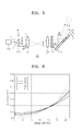
- FIG. 5 illustrates an optical configuration and an optical path when a torsion oscillator rotates clockwise from the original position, according to an embodiment of the present invention
- FIG. 6 is a graph of a compensation quantity for distortion of a sinusoidal compensation lens with respect to a deflection angle of a torsion oscillator
- FIG. 7 illustrates an optical configuration of a light scanning unit, according to another embodiment of the present invention.
- FIG. 8 illustrates a light source unit according to an embodiment of the present invention, which may be used in the light scanning unit of FIG. 7 ;
- FIGS. 9 through 11 illustrate an operation of the light scanning unit of FIG. 7 , according to an embodiment of the present invention.
- FIG. 1 illustrates an optical configuration of a light scanning unit 100 according to an embodiment of the present invention.
- the light scanning unit 100 may include a light source unit 110 emitting a collimated light beam, an incident angle compensation lens 150 compensating for a field angle of the collimated light beam, a cylindrical lens 160 focusing the collimated light beam in a sub-scanning direction, and a torsion oscillator 170 that deflects and scans the collimated light beam.
- the light source unit 110 may include a light source 120 and a collimation lens 130.
- the light source 120 may be, e.g., a semiconductor laser diode emitting a laser beam.
- the collimation lens 130 collimates the light beam emitted from the light source 120.
- the focal point location at a light-receiving surface of the collimation lens 130 may be positioned at the origin of the light source 120 as illustrated in FIG. 3 .
- the focal length of the collimation lens 130 is indicated by "f1."
- the collimation lens 130 may be driven to oscillate in synchronization with oscillation "A" of the torsion oscillator 170.
- Oscillation "B" of the collimation lens 130 may be achieved by, e.g., using an actuator using electromagnetic force.
- the oscillation "B" of the collimation lens 130 may be created in a perpendicular direction to an optical path of the collimated light beam. Due to the oscillation "B" of the collimation lens 130, the collimated light beam that is incident on the torsion oscillator 170 oscillates synchronously with the oscillation "A" of the torsion oscillator 170, and the incident angle of the collimated light beam is accordingly changed, thereby enlarging the deflection angle of the torsion oscillator 170, as will be described in more detail later.
- the oscillation "B" of the collimation lens 130 will be described in more detail with reference to FIGS. 3 through 5 .
- the incident angle compensation lens 150 compensates for the change in the angle of optical path of the collimated light beam so that the oscillating collimated light beam proceeds towards the center of a mirror surface of the torsion oscillator 170.
- the incident angle compensation lens 150 may include at least two lenses, for example, first and second part lenses 151 and 152 constituting a 4F system. Referring to FIG. 3 , the focal point location of the first part lens 151 at a light-receiving side is positioned at an origin of the collimation lens 130 at which a field is generated, that is, a field-generating origin of the light source unit 110.
- a focal point location of the second part lens 152 at a light emitting side is positioned at the center of the mirror surface of the torsion oscillator 170.
- the focal length of the first part lens 151 is indicated by "F1”
- the focal length of the second part lens 152 is indicated by "F2”.
- the interval "D" between the first and second part lenses 151 and 152 may preferably be a value equal to or smaller than the sum of the focal lengths of the first and second part lenses 151 and 152.
- the incident angle compensation lens 150 constituting the 4F system transfers an image (i.e., a light beam) from the collimation lens 130 to the mirror surface of the torsion oscillator 170.
- the size of the image may be changed according to the ratio of F1/F2. While, in this embodiment, in order to minimize the size of the torsion oscillator 170, the incident angle compensation lens 150 is preferably provided, the incident angle compensation lens 150 however is not essential, and may be omitted in other embodiments.
- the oscillation "B" of the light source unit 110 or refraction of the incident angle compensation lens 150 affects the scanning direction of the torsion oscillator 170.
- the optical path variation of a light beam that is scanned by the torsion oscillator 170 due to the oscillation "B" of the light source unit 110 and the refraction of the incident angle compensation lens 150 may take place along the scanning plane, along which the light beam from the torsion oscillator 170 is scanned.
- FIGS. 1 and 3 through 5 each illustrate an optical configuration on the scanning plane.
- the cylindrical lens 160 has refractive power in the sub-scanning direction so that the collimated light beam is focused on the mirror surface of the torsion oscillator 170 in the sub-scanning direction.
- the sub-scanning direction refers to a direction perpendicular to the scanning direction of the torsion oscillator 170, i.e., the direction perpendicular to the scanning plane. Since the cylindrical lens 160 does not have refractive power with regard to the scanning direction of the oscillator 170, the cylindrical lens 160 does not affect the optical path variation of the collimated light beam on the scanning plane resulting from the oscillation "B" of the light source unit 110 and the refraction of the incident angle compensation lens 150.
- cylindrical lens 160 is not an essential element in practicing the embodiment, and may be omitted. Moreover, the cylindrical lens 160 is an optical element that is typically utilized in an image forming apparatus such as a printer, and is well known to those skilled in the art, the detailed description thereof is not necessary.
- the torsion oscillator 170 deflects and scans the collimated light beam, and is an example of a beam deflector.
- FIG. 2 illustrates a torsion oscillator 170 according to an embodiment of the present invention.
- the torsion oscillator 170 may include a mirror 171 suspended above a substrate 175, a support 176 supporting either end of the mirror 171, a torsion spring 172 connected between the mirror 171 and the support 176 to support a seesaw-like motion of the mirror 171, a plurality of movable comb electrodes 173 which are formed on both side surfaces of the mirror 171 to extend perpendicularly from the side surfaces of the mirror 171, and a plurality of fixed comb electrodes 174 which are formed on the substrate 175 in a perpendicular direction to the substrate 175.
- the movable comb electrodes 173 and the fixed comb electrodes 174 are alternately disposed.
- the torsion oscillator 170 inclines the mirror 171 to one side via an electrostatic force between the movable comb electrodes 173 and the fixed comb electrodes 174, and restores the mirror 171 back to an original position by using a restoring force that is generated by a modulus of elasticity of the torsion spring 172. Consequently, the mirror 171 oscillates due to the torsion, thereby creating sinusoidal oscillation.
- the torsion oscillator 170 is described as an example of a beam deflector, the present invention however is not limited thereto. Other beam reflectors may be used in alternative embodiments to enhance the maximum deflection angle of the beam deflector being utilized.
- An oscillation frequency of the torsion oscillator 170 is related to the size of the mirror 171.
- the oscillation frequency of the torsion oscillator 170 is reduced as the size of the mirror 171 is increased.
- the size of the mirror 171 may be minimized to realize a high oscillation frequency.
- the incident angle compensation lens 150 may be provided. The incident angle compensation lens 150 compensates for the angle of the path of the oscillating collimated light beam so that the oscillating collimated light beam proceeds towards the center of the mirror 171 of the torsion oscillator 170, thereby allowing the size of the mirror 171 to be reduced.
- the collimation lens 130 may be made to oscillate synchronously with the oscillation "A" of the torsion oscillator 170.
- the deflection angle that is equal to or greater than the oscillating angle of the torsion oscillator 170.
- a focusing optical element 190 is an optical lens that focuses a light beam deflected by the torsion oscillator 170 onto an exposed surface 200.
- the torsion oscillator 170 is used as a beam deflector.
- the light beam deflected by the torsion oscillator 170 traces a sinusoidal trajectory.
- the focusing optical element 190 may be a sinusoidal trajectory compensation lens, i.e., an arc-sinusoidal lens that compensates for the light beam deflected by the torsion oscillator 170 into a light beam having an arc-sinusoidal form so that the deflected light beam is scanned onto the exposed surface 200 at equal intervals.
- FIG. 3 illustrates the case where a torsion oscillator 170 is at its original position.
- FIG. 4 illustrates the case where the torsion oscillator 170 rotates counterclockwise from the original position.
- FIG. 5 illustrates the case where the torsion oscillator 170 rotates clockwise from the original position.
- the torsion oscillator 170 and the collimation lens 130 are at their original positions, e.g., at the center position within the range of oscillation.
- a light beam "L” emitted from a light source 120 is transmitted through the collimation lens 130 at its original position, collimated into a light beam "L1", transmitted through the incident angle compensation lens 150, and is reflected by the torsion oscillator 170.
- a path of the light beam "L1" from the collimation lens 130 to the torsion oscillator 170 is parallel to an optical axis "C" of the incident angle compensation lens 150, e.g., the first and second part lenses 151 and 152.
- the collimation lens 130 moves in synchronization with the torsion oscillator 170 so that the collimation lens 130 oscillates upwards by a distance "d1.”
- the torsion oscillator 170 as indicated by the dotted lines represents the torsion oscillator 170 being at the original position.
- the light beam "L” incident on the collimation lens 130 is collimated into a light beam "L2" that proceeds upwards so as to be inclined with respect to the optical axis "C” at a first field angle " ⁇ 1".
- the first field angle " ⁇ 1" is approximately given by Equation 1 below, where “f1" is the focal length of the collimation lens 130 and “d1" is the amount of oscillation of the collimation lens 130.
- ⁇ ⁇ 1 tan - 1 ⁇ d ⁇ 1 f ⁇ 1
- the light beam "L2" that is collimated into the light beam directed in the inclined direction is transmitted through the incident angle compensation lens 150 towards the torsion oscillator 170.
- the first and second part lenses 151 and 152 included in the incident angle compensation lens 150 may constitute a 4F system, and transfer the light beam from the collimation lens 130 to the mirror surface of the torsion oscillator 170.
- the collimated light beam "L2" transmitted through the incident angle compensation lens 150 travels in the direction towards the center of the mirror 171 of the torsion oscillator 170.
- the second field angle " ⁇ 2" of the light beam incident on the torsion oscillator 170 may be changed according to the ratio of F1/F2 of the first and second part lenses 151 and 152, and is approximately given by Equation 2 below.
- ⁇ ⁇ 2 ⁇ ⁇ 1 ⁇ F ⁇ 1 F ⁇ 2
- the light beam "L2" incident on the torsion oscillator 170 at the second field angle “ ⁇ 2” is reflected while being deflected at an angle equal to or greater than the oscillating angle of the torsion oscillator 170.
- the maximum deflection angle “ ⁇ M " of the light beam “L2” that is deflected on the torsion oscillator 170, whose the maximum oscillating angle is ⁇ M is given by Equation 3 below.
- the maximum deflection angle ⁇ M refers to a deflection angle of the case where the mirror 171 (see FIG. 2 ) of the torsion oscillator 170 oscillates from an original position to one side, and thus a total deflection angle with regard to both right and left oscillations is twice as much as ⁇ M .
- the collimation lens 130 oscillates downwards synchronously with the torsion oscillator 170 by a distance “d1" (B").
- the torsion oscillator 170 indicted by the dotted lines represents the torsion oscillator 170 being at the original position.
- the light beam "L” incident on the collimation lens 130 is collimated into a light beam "L3” that travels downwards so as to be inclined with respect to the optical axis "C” at a first field angle " ⁇ 1"
- the first field angle " ⁇ 1” is given by Equation 1 above.
- the light beam “L3” that is collimated into a parallel light beam inclined downwards is transmitted through the incident angle compensation lens 150 towards the torsion oscillator 170.
- the collimated light beam “L3” transmitted through the incident angle compensation lens 150 travels in a convergent direction towards the center of the mirror 171 of the torsion oscillator 170.
- the second field angle “ ⁇ 2" of the light beam incident on the torsion oscillator 170 is given by Equation 2 above.
- the maximum deflection angle “ ⁇ M " with respect to the maximum oscillating angle " ⁇ M " of the torsion oscillator 170 is given by Equation 3 above.
- the mirror 171 of the torsion oscillator 170 creates sinusoidal oscillation.
- a light beam that oscillates and that is reflected off the torsion oscillator 170 oscillates at an angle " ⁇ " that is given by Equation 4 below.
- the angle " ⁇ " above is a deflection angle in the case where the mirror 171 is inclined in one direction with respect to its original position.
- the collimation lens 130 oscillates in synchronization with the oscillation of the torsion oscillator 170, and thus, the maximum deflection angle " ⁇ M " with regard to the torsion oscillator 170 is the sum of the maximum oscillating angle " ⁇ M " of the torsion oscillator 170 and ⁇ 1*F1/F2, thereby increasing a total deflection angle by 2* ⁇ 1*F1/F2.
- FIG. 6 is a graph of a compensation quantity "dy/d ⁇ " for distortion of a sinusoidal compensation lens with respect to a deflection angle of the torsion oscillator 170, according to an embodiment of the present invention.
- the sum of ⁇ 1 and ⁇ 2 represents the increase of 4.6° of the deflection angle from the oscillating angle of the torsion oscillator.
- FIG. 7 illustrates an optical configuration of a light scanning unit 300 according to another embodiment of the present invention.
- the light scanning unit 300 includes a light source unit 310 emitting a collimated light beam, an incident angle compensation lens 150 compensating for a field angle of the collimated light beam, a cylindrical lens 160 focusing the collimated light beam in the sub-scanning direction and a torsion oscillator 170 that deflects and scans the collimated light.
- the light source unit 310 includes a light source 320, a collimation lens 330 collimating the light beam emitted from the light source 320, and a holder 340 integrally supporting both the light source 320 and the collimation lens 330.
- the light source unit 310 may be manufactured as an integrated structure, and changes the direction of a light beam that is collimated due to a tilt angle of the light source unit 310.
- the light source unit 310 having the integrated structure can be manufactured into a compact structure by using micro-electromechanical systems (MEMS) technology that has recently seen wide usage.
- MEMS micro-electromechanical systems
- a semiconductor laser diode e.g., an edge emitting type laser diode or a vertical cavity surface emitting laser (VCSEL)
- VCSEL vertical cavity surface emitting laser
- the light source unit 310 may be driven to tilt-oscillate synchronously with the oscillation "A" of the torsion oscillator 170.
- the light source unit 310 having the integrated structure may be driven by an actuator using electromagnetic force.
- the light source unit 310 when the light source unit 310 is manufactured using MEMS technology, the light source unit 310 may be driven by static electricity similar to the manner in which the torsion oscillator 170 is driven.
- Tilt-oscillation "B" of the light source unit 310 is applied so that the collimated light beam that is incident on the torsion oscillator 170 oscillates synchronously with the oscillation of the torsion oscillator 170, and thus an incident angle at which the collimated light beam is incident on the torsion oscillator 170 is changed.
- the light source unit 310 tilt-oscillates, the light source unit 310 can directly change the incident angle.
- the incident angle compensation lens 150 compensates for the angle of path of the collimated light beam so that the oscillating collimated light beam travels towards the center of a mirror surface of the torsion oscillator 170.
- the cylindrical lens 160 is applied so that the collimated light beam is focused on the mirror surface of the torsion oscillator 170 in the sub-scanning direction.
- the torsion oscillator 170 deflects and scans the collimated light beam.
- the focusing optical element 190 focuses the light beam that is deflected from the torsion oscillator 170 onto the exposed surface 200.
- the optical configuration is the same as that in FIG. 1 except for the light source unit 310, and thus the descriptions of those elements common to both embodiments will not be repeated.
- FIG. 9 illustrates the case where a torsion oscillator 170 is at its original position.
- FIG. 10 illustrates the case where the torsion oscillator 170 rotates counterclockwise from the original position.
- FIG. 11 illustrates the case where a torsion oscillator 170 rotates clockwise from the original position.
- the light source unit 310 and the torsion oscillator 170 are at their respective original positions, that is, the center position within the range of oscillation.
- a collimated light beam "L1" that from the light source unit 310 is transmitted through the incident angle compensation lens 150 to be incident on the torsion oscillator 170.
- the path of the collimated light beam "L1” is parallel to the optical axis "C" of the incident angle compensation lens 150.
- the torsion oscillator 170 rotates counterclockwise (A') from the original position, the light source unit 310 synchronously therewith tilt-oscillate (B') upwards.
- the torsion oscillator 170 indicated by the dotted lines represents the torsion oscillator 170 being at the original position.
- a collimated light beam "L2" that travels at an upward incline from the light source unit 310, that is, in a divergent direction, is transmitted through the incident angle compensation lens 150 towards the torsion oscillator 170.
- the collimated light beam “L2" transmitted through the incident angle compensation lens 150 proceeds in a convergent direction towards the center of the mirror 171 of the torsion oscillator 170.
- the light beam “L2" incident on the torsion oscillator 170 at an incline is deflected at an angle equal to or greater than the oscillating angle of the torsion oscillator 170, and is reflected off the torsion oscillator 170.
- the maximum deflection angle " ⁇ M " of the light beam “L2" that is deflected by the torsion oscillator 170 is given by Equation 3 above.
- the torsion oscillator 170 rotates clockwise (A") from the original position, the light source unit 310 synchronously therewith tilt-oscillate downward.
- the torsion oscillator 170 indicated by the dotted lines represents the torsion oscillator 170 being at the original position.
- the collimated light beam "L3" that is emitted downwards from the light source unit 310 is transmitted through the incident angle compensation lens 150 in a direction towards the torsion oscillator 170 along the optical axis "C".
- the collimated light beam "L3" transmitted through the incident angle compensation lens 150 proceeds in a convergent direction towards the center of the mirror 171 of the torsion oscillator 170.
- the collimated light beam "L3" incident on the torsion oscillator 170 with the upward incline is deflected at an angle that is equal to or greater than the oscillating angle of the torsion oscillator 170, and is reflected off the torsion oscillator 170.
- the maximum deflection angle " ⁇ M " with respect to the maximum oscillating angle " ⁇ M " is given by Equation 3 above.
- the mirror 171 of the torsion oscillator 170 creates sinusoidal oscillation
- the light beam reflected off the torsion oscillator 170 oscillates at an angle " ⁇ " that is given by Equation 4 above.
- the light scanning unit 100 or 300 may be used in an image forming apparatus, such as a duplicator, a printer, a facsimile, or the like, that utilizes electrophotograph in realizing an image on a printing paper.
- the exposed surface 200 may be a photosensitive medium such as a photoreceptor drum.
- the exposed surface 200 is moved in a direction, and an electrostatic latent image is formed on the exposed surface 200 by a light beam scanned by the light scanning unit 100 or 300.
- the electrostatic latent image formed on the exposed surface 200 may be developed into a visible image by toner provided by a developer unit (not shown).
- the light scanning unit 100 or 300 may be used in an image forming apparatus such as a laser display apparatus on which a laser beam is scanned on a screen so as to display an image on the screen.
- the exposed surface 200 may be a screen, and the light scanning unit 100 or 300 may be used for horizontal-scanning or vertical-scanning.
- a deflection angle can be enlarged by employing the light scanning unit 100 or 300.
- the design of a sinusoidal compensation lens may be easier, and the distance between the light scanning unit 100 or 300 and the exposed surface 200 can be reduced, thereby obtaining a compact and slim structure.
Landscapes
- Physics & Mathematics (AREA)
- General Physics & Mathematics (AREA)
- Optics & Photonics (AREA)
- Facsimile Scanning Arrangements (AREA)
- Laser Beam Printer (AREA)
- Mechanical Optical Scanning Systems (AREA)
Applications Claiming Priority (1)
| Application Number | Priority Date | Filing Date | Title |
|---|---|---|---|
| KR1020080031713A KR20090106168A (ko) | 2008-04-04 | 2008-04-04 | 광주사 장치, 이를 채용한 화상 형성 장치 및 광주사 방법 |
Publications (2)
| Publication Number | Publication Date |
|---|---|
| EP2107411A2 true EP2107411A2 (de) | 2009-10-07 |
| EP2107411A3 EP2107411A3 (de) | 2010-07-07 |
Family
ID=40903689
Family Applications (1)
| Application Number | Title | Priority Date | Filing Date |
|---|---|---|---|
| EP09156601A Withdrawn EP2107411A3 (de) | 2008-04-04 | 2009-03-30 | Lichtabtasteinheit, Bilderzeugungsvorrichtung damit und Lichtabtastverfahren |
Country Status (5)
| Country | Link |
|---|---|
| US (1) | US20090251754A1 (de) |
| EP (1) | EP2107411A3 (de) |
| JP (1) | JP2009251596A (de) |
| KR (1) | KR20090106168A (de) |
| CN (1) | CN101551521A (de) |
Families Citing this family (7)
| Publication number | Priority date | Publication date | Assignee | Title |
|---|---|---|---|---|
| WO2011058884A1 (ja) | 2009-11-16 | 2011-05-19 | 日本電気株式会社 | 光走査装置 |
| US9310609B2 (en) * | 2014-07-25 | 2016-04-12 | Hand Held Products, Inc. | Axially reinforced flexible scan element |
| US9924115B2 (en) * | 2015-09-23 | 2018-03-20 | Agilent Technologies, Inc. | Apparatus and method for three-dimensional infrared imaging of surfaces |
| CN107655861A (zh) * | 2017-11-08 | 2018-02-02 | 北京英柏生物科技有限公司 | 表面等离子体子谐振检测仪 |
| CN111527439B (zh) * | 2017-12-22 | 2023-02-03 | 麦斯卓微电子(南京)有限公司 | Mems致动系统 |
| DE102019207073B4 (de) * | 2019-05-15 | 2021-02-18 | OQmented GmbH | Bilderzeugungseinrichtung für ein scannendes Projektionsverfahren mit Bessel-ähnlichen Strahlen |
| CN110133842B (zh) * | 2019-06-28 | 2024-03-12 | 岗春激光科技(江苏)有限公司 | 一种振镜扫描装置及系统 |
Citations (1)
| Publication number | Priority date | Publication date | Assignee | Title |
|---|---|---|---|---|
| US7184187B2 (en) | 2003-10-20 | 2007-02-27 | Lexmark International, Inc. | Optical system for torsion oscillator laser scanning unit |
Family Cites Families (10)
| Publication number | Priority date | Publication date | Assignee | Title |
|---|---|---|---|---|
| JPS5397447A (en) * | 1977-02-04 | 1978-08-25 | Canon Inc | Optical scanning system |
| JPS63138534A (ja) * | 1986-11-29 | 1988-06-10 | Sony Corp | 光記録再生装置 |
| JPH01131515A (ja) * | 1987-06-26 | 1989-05-24 | Ricoh Co Ltd | 光走査方法 |
| JPH0636311A (ja) * | 1992-07-16 | 1994-02-10 | Sankyo Seiki Mfg Co Ltd | 光テープ斜め走査方法および光学ヘッド装置 |
| JP3311506B2 (ja) * | 1994-09-02 | 2002-08-05 | 株式会社リコー | 光走査装置及び光書込装置 |
| JPH1195148A (ja) * | 1997-09-22 | 1999-04-09 | Minolta Co Ltd | 走査機構 |
| JPH11352434A (ja) * | 1998-06-08 | 1999-12-24 | Sankyo Seiki Mfg Co Ltd | ビーム走査装置 |
| US7440002B2 (en) * | 2003-09-17 | 2008-10-21 | Seiko Epson Corporation | Optical scanning apparatus and image forming apparatus |
| JP4496747B2 (ja) * | 2003-09-29 | 2010-07-07 | セイコーエプソン株式会社 | 光走査装置および画像形成装置 |
| US7436564B2 (en) * | 2005-08-03 | 2008-10-14 | Seiko Epson Corporation | Light scanning apparatus and method to prevent damage to an oscillation mirror in an abnormal control condition via a detection signal outputted to a controller even though the source still emits light |
-
2008
- 2008-04-04 KR KR1020080031713A patent/KR20090106168A/ko not_active Withdrawn
- 2008-11-04 US US12/264,561 patent/US20090251754A1/en not_active Abandoned
-
2009
- 2009-03-06 JP JP2009053803A patent/JP2009251596A/ja not_active Ceased
- 2009-03-17 CN CNA2009101288354A patent/CN101551521A/zh active Pending
- 2009-03-30 EP EP09156601A patent/EP2107411A3/de not_active Withdrawn
Patent Citations (1)
| Publication number | Priority date | Publication date | Assignee | Title |
|---|---|---|---|---|
| US7184187B2 (en) | 2003-10-20 | 2007-02-27 | Lexmark International, Inc. | Optical system for torsion oscillator laser scanning unit |
Also Published As
| Publication number | Publication date |
|---|---|
| CN101551521A (zh) | 2009-10-07 |
| US20090251754A1 (en) | 2009-10-08 |
| KR20090106168A (ko) | 2009-10-08 |
| EP2107411A3 (de) | 2010-07-07 |
| JP2009251596A (ja) | 2009-10-29 |
Similar Documents
| Publication | Publication Date | Title |
|---|---|---|
| US5054866A (en) | Scanning optical apparatus | |
| EP2107411A2 (de) | Lichtabtasteinheit, Bilderzeugungsvorrichtung damit und Lichtabtastverfahren | |
| KR100742882B1 (ko) | 광편향기 | |
| US7773280B2 (en) | Optical scanning device and image forming apparatus | |
| US8593701B2 (en) | Optical scanning device and image forming apparatus | |
| JP2009192563A (ja) | 光走査装置及び画像形成装置 | |
| US7184187B2 (en) | Optical system for torsion oscillator laser scanning unit | |
| EP1773596B1 (de) | Bidirektionaler multilaserdrucker mit einem oszillierenden abtastspiegel | |
| JP2009069504A (ja) | 光走査装置、および画像形成装置 | |
| KR100319354B1 (ko) | 광학 주사 장치, 및 이 장치를 이용한 화상 형성 장치 및전기 사진 프린터 | |
| JP2016033651A (ja) | 光偏向器、光走査装置、画像形成装置、画像投影装置及びヘッドアップディスプレイ | |
| JP2009020484A (ja) | 揺動体装置、光偏向装置、及びその制御方法 | |
| JP4551559B2 (ja) | 走査光学装置及びそれを用いた画像形成装置 | |
| JPH11305159A (ja) | 微小揺動ミラー素子及びこれを用いたレーザ走査装置 | |
| KR101109286B1 (ko) | 요동 구조체, 그것을 사용한 요동체 장치, 광편향 장치 및 화상 형성 장치 | |
| JP2015129801A (ja) | 光偏向装置、光走査装置、画像表示装置及び画像形成装置 | |
| JP2010122248A (ja) | 光走査装置および画像形成装置 | |
| JP2002258204A (ja) | 光走査装置及び画像形成装置 | |
| KR100954906B1 (ko) | 광주사장치 및 그것을 이용한 화상형성장치 | |
| JP2008197453A (ja) | 走査光学装置及びそれを用いた画像形成装置 | |
| JPH0328818A (ja) | 走査光学装置 | |
| JP3784591B2 (ja) | 走査結像光学系・光走査装置および画像形成装置 | |
| JP2007219083A (ja) | 光走査装置及びそれを用いた画像形成装置 | |
| JP2009095208A (ja) | 揺動体装置、揺動体装置を用いた光偏向器及び画像形成装置 | |
| JP2007163817A (ja) | 光偏向器、及びそれを用いた光学機器 |
Legal Events
| Date | Code | Title | Description |
|---|---|---|---|
| PUAI | Public reference made under article 153(3) epc to a published international application that has entered the european phase |
Free format text: ORIGINAL CODE: 0009012 |
|
| AK | Designated contracting states |
Kind code of ref document: A2 Designated state(s): AT BE BG CH CY CZ DE DK EE ES FI FR GB GR HR HU IE IS IT LI LT LU LV MC MK MT NL NO PL PT RO SE SI SK TR |
|
| AX | Request for extension of the european patent |
Extension state: AL BA RS |
|
| PUAL | Search report despatched |
Free format text: ORIGINAL CODE: 0009013 |
|
| AK | Designated contracting states |
Kind code of ref document: A3 Designated state(s): AT BE BG CH CY CZ DE DK EE ES FI FR GB GR HR HU IE IS IT LI LT LU LV MC MK MT NL NO PL PT RO SE SI SK TR |
|
| AX | Request for extension of the european patent |
Extension state: AL BA RS |
|
| 17P | Request for examination filed |
Effective date: 20110107 |
|
| AKX | Designation fees paid |
Designated state(s): DE GB NL |
|
| 17Q | First examination report despatched |
Effective date: 20111005 |
|
| STAA | Information on the status of an ep patent application or granted ep patent |
Free format text: STATUS: THE APPLICATION IS DEEMED TO BE WITHDRAWN |
|
| 18D | Application deemed to be withdrawn |
Effective date: 20120417 |