EP2107431A2 - Dispositif de fixation et appareil de formation d'images - Google Patents
Dispositif de fixation et appareil de formation d'images Download PDFInfo
- Publication number
- EP2107431A2 EP2107431A2 EP09250840A EP09250840A EP2107431A2 EP 2107431 A2 EP2107431 A2 EP 2107431A2 EP 09250840 A EP09250840 A EP 09250840A EP 09250840 A EP09250840 A EP 09250840A EP 2107431 A2 EP2107431 A2 EP 2107431A2
- Authority
- EP
- European Patent Office
- Prior art keywords
- fixing device
- fixing
- image forming
- forming apparatus
- support shaft
- Prior art date
- Legal status (The legal status is an assumption and is not a legal conclusion. Google has not performed a legal analysis and makes no representation as to the accuracy of the status listed.)
- Granted
Links
- 230000005540 biological transmission Effects 0.000 claims description 13
- 238000012546 transfer Methods 0.000 description 27
- 239000010410 layer Substances 0.000 description 20
- 238000010438 heat treatment Methods 0.000 description 17
- 229910052751 metal Inorganic materials 0.000 description 6
- 239000002184 metal Substances 0.000 description 6
- 230000007246 mechanism Effects 0.000 description 5
- XEEYBQQBJWHFJM-UHFFFAOYSA-N Iron Chemical compound [Fe] XEEYBQQBJWHFJM-UHFFFAOYSA-N 0.000 description 4
- 238000011161 development Methods 0.000 description 4
- 238000012986 modification Methods 0.000 description 4
- 230000004048 modification Effects 0.000 description 4
- 238000000926 separation method Methods 0.000 description 4
- 229920002379 silicone rubber Polymers 0.000 description 4
- 238000012360 testing method Methods 0.000 description 4
- 229910052782 aluminium Inorganic materials 0.000 description 3
- XAGFODPZIPBFFR-UHFFFAOYSA-N aluminium Chemical compound [Al] XAGFODPZIPBFFR-UHFFFAOYSA-N 0.000 description 3
- 230000015572 biosynthetic process Effects 0.000 description 3
- 230000003247 decreasing effect Effects 0.000 description 3
- 229920011301 perfluoro alkoxyl alkane Polymers 0.000 description 3
- 229920001343 polytetrafluoroethylene Polymers 0.000 description 3
- 239000004810 polytetrafluoroethylene Substances 0.000 description 3
- 239000011347 resin Substances 0.000 description 3
- 229920005989 resin Polymers 0.000 description 3
- PXHVJJICTQNCMI-UHFFFAOYSA-N Nickel Chemical compound [Ni] PXHVJJICTQNCMI-UHFFFAOYSA-N 0.000 description 2
- 239000004642 Polyimide Substances 0.000 description 2
- 229920001971 elastomer Polymers 0.000 description 2
- 229910052742 iron Inorganic materials 0.000 description 2
- 239000000463 material Substances 0.000 description 2
- 230000003287 optical effect Effects 0.000 description 2
- 229920001721 polyimide Polymers 0.000 description 2
- 238000007639 printing Methods 0.000 description 2
- 230000002787 reinforcement Effects 0.000 description 2
- XUIMIQQOPSSXEZ-UHFFFAOYSA-N Silicon Chemical group [Si] XUIMIQQOPSSXEZ-UHFFFAOYSA-N 0.000 description 1
- 230000002159 abnormal effect Effects 0.000 description 1
- 238000010521 absorption reaction Methods 0.000 description 1
- 238000013459 approach Methods 0.000 description 1
- 239000000969 carrier Substances 0.000 description 1
- 239000000919 ceramic Substances 0.000 description 1
- 230000000295 complement effect Effects 0.000 description 1
- 239000000470 constituent Substances 0.000 description 1
- 229920001577 copolymer Polymers 0.000 description 1
- 230000008878 coupling Effects 0.000 description 1
- 238000010168 coupling process Methods 0.000 description 1
- 238000005859 coupling reaction Methods 0.000 description 1
- 238000007599 discharging Methods 0.000 description 1
- 238000005516 engineering process Methods 0.000 description 1
- 238000011156 evaluation Methods 0.000 description 1
- 229910052736 halogen Inorganic materials 0.000 description 1
- 150000002367 halogens Chemical class 0.000 description 1
- 230000006698 induction Effects 0.000 description 1
- 238000003780 insertion Methods 0.000 description 1
- 230000037431 insertion Effects 0.000 description 1
- 238000003475 lamination Methods 0.000 description 1
- 238000000034 method Methods 0.000 description 1
- 229910052759 nickel Inorganic materials 0.000 description 1
- 229920013653 perfluoroalkoxyethylene Polymers 0.000 description 1
- 230000002093 peripheral effect Effects 0.000 description 1
- -1 polytetrafluoroethylene Polymers 0.000 description 1
- 229910052710 silicon Inorganic materials 0.000 description 1
- 239000010703 silicon Substances 0.000 description 1
- 239000004945 silicone rubber Substances 0.000 description 1
- 239000007787 solid Substances 0.000 description 1
- 229910001220 stainless steel Inorganic materials 0.000 description 1
- 239000010935 stainless steel Substances 0.000 description 1
- 239000002344 surface layer Substances 0.000 description 1
- BFKJFAAPBSQJPD-UHFFFAOYSA-N tetrafluoroethene Chemical group FC(F)=C(F)F BFKJFAAPBSQJPD-UHFFFAOYSA-N 0.000 description 1
Images





Classifications
-
- G—PHYSICS
- G03—PHOTOGRAPHY; CINEMATOGRAPHY; ANALOGOUS TECHNIQUES USING WAVES OTHER THAN OPTICAL WAVES; ELECTROGRAPHY; HOLOGRAPHY
- G03G—ELECTROGRAPHY; ELECTROPHOTOGRAPHY; MAGNETOGRAPHY
- G03G21/00—Arrangements not provided for by groups G03G13/00 - G03G19/00, e.g. cleaning, elimination of residual charge
- G03G21/16—Mechanical means for facilitating the maintenance of the apparatus, e.g. modular arrangements
- G03G21/1661—Mechanical means for facilitating the maintenance of the apparatus, e.g. modular arrangements means for handling parts of the apparatus in the apparatus
- G03G21/1685—Mechanical means for facilitating the maintenance of the apparatus, e.g. modular arrangements means for handling parts of the apparatus in the apparatus for the fixing unit
-
- G—PHYSICS
- G03—PHOTOGRAPHY; CINEMATOGRAPHY; ANALOGOUS TECHNIQUES USING WAVES OTHER THAN OPTICAL WAVES; ELECTROGRAPHY; HOLOGRAPHY
- G03G—ELECTROGRAPHY; ELECTROPHOTOGRAPHY; MAGNETOGRAPHY
- G03G15/00—Apparatus for electrographic processes using a charge pattern
- G03G15/20—Apparatus for electrographic processes using a charge pattern for fixing, e.g. by using heat
- G03G15/2003—Apparatus for electrographic processes using a charge pattern for fixing, e.g. by using heat using heat
- G03G15/2014—Apparatus for electrographic processes using a charge pattern for fixing, e.g. by using heat using heat using contact heat
- G03G15/2017—Structural details of the fixing unit in general, e.g. cooling means, heat shielding means
- G03G15/2032—Retractable heating or pressure unit
- G03G15/2035—Retractable heating or pressure unit for maintenance purposes, e.g. for removing a jammed sheet
-
- G—PHYSICS
- G03—PHOTOGRAPHY; CINEMATOGRAPHY; ANALOGOUS TECHNIQUES USING WAVES OTHER THAN OPTICAL WAVES; ELECTROGRAPHY; HOLOGRAPHY
- G03G—ELECTROGRAPHY; ELECTROPHOTOGRAPHY; MAGNETOGRAPHY
- G03G15/00—Apparatus for electrographic processes using a charge pattern
- G03G15/20—Apparatus for electrographic processes using a charge pattern for fixing, e.g. by using heat
- G03G15/2003—Apparatus for electrographic processes using a charge pattern for fixing, e.g. by using heat using heat
- G03G15/2014—Apparatus for electrographic processes using a charge pattern for fixing, e.g. by using heat using heat using contact heat
- G03G15/2064—Apparatus for electrographic processes using a charge pattern for fixing, e.g. by using heat using heat using contact heat combined with pressure
-
- G—PHYSICS
- G03—PHOTOGRAPHY; CINEMATOGRAPHY; ANALOGOUS TECHNIQUES USING WAVES OTHER THAN OPTICAL WAVES; ELECTROGRAPHY; HOLOGRAPHY
- G03G—ELECTROGRAPHY; ELECTROPHOTOGRAPHY; MAGNETOGRAPHY
- G03G2221/00—Processes not provided for by group G03G2215/00, e.g. cleaning or residual charge elimination
- G03G2221/16—Mechanical means for facilitating the maintenance of the apparatus, e.g. modular arrangements and complete machine concepts
- G03G2221/1639—Mechanical means for facilitating the maintenance of the apparatus, e.g. modular arrangements and complete machine concepts for the fixing unit
Definitions
- Example embodiments generally relate to a fixing device and an image forming apparatus, for example, for efficiently fixing a toner image on a recording medium using a rotatable fixing member.
- Image forming apparatuses such as copiers, facsimile machines, printers, and multifunction devices having at least one of copying, printing, scanning, and facsimile functions, typically form a toner image on a recording medium (e.g., a sheet) based on image data using electrophotography.
- a recording medium e.g., a sheet
- a development device develops the electrostatic latent image with a developer (e.g., toner) into a visible toner image.
- a transfer device transfers the toner image onto a sheet
- the toner image is fixed on the sheet by heat and pressure applied by a fixing device. Then, the sheet is discharged to the outside of the image forming apparatus via a discharge path.
- FIGS. 1A and 1B illustrate one example of a related-art fixing device 900R.
- Left and right side plates 97A and 97B are vertically provided on a bottom plate 97C, as illustrated in FIG. 1B , and support a fixing roller 11R, a heating roller 14R, and a pressing roller 13R, respectively, as illustrated in FIG. 1A .
- a fixing belt 12R is wrapped around the fixing roller 11R and the heating roller 14R under an appropriate amount of tension supplied by a tension roller 15AR.
- the side plates 97A and 97B are reinforced by the bottom plate 97C, stays, and the like, so as to keep the respective rollers parallel to each other.
- positioning members 98A and 98B engage a supporting member of the image forming apparatus so that the fixing device 900R is positioned in a predetermined place.
- the positioning members 98A and 98B are fixed to the side plates 97A and 97B by swaging and extend from a fixing cover 900C.
- the right side plate 97A supports a drive input gear 99A with a support shaft, not shown, provided outside the fixing device 900R.
- the drive input gear 99A serving as a drive input rotating body, receives a driving force transmitted from the outside (the image forming apparatus).
- a rotary shaft of the pressing roller 13R extends from the right side plate 97A.
- a pressing roller gear 99C is provided at one end of the rotary shaft of the pressing roller 13R in an axial direction of the rotary shaft.
- the drive input gear 99A Upon receipt of the driving force transmitted from the image forming apparatus, the drive input gear 99A rotates.
- the rotation of the drive input gear 99A is transmitted to the pressing roller gear 99C via an idler gear 99B, the pressing roller 13R rotates.
- the fixing belt 12R is driven to rotate as the pressing roller 13R rotates.
- the fixing device 900R When the fixing device 900R is attached to the image forming apparatus, a user moves the fixing device 900R in a direction perpendicular to shaft lines of the positioning members 98A and 98B, with a surface of the fixing device 900R on which a drawer connector 9A is provided facing toward the back of the image forming apparatus, so that the fixing device 900R is installed in a predetermined position of the image forming apparatus.
- the shaft lines of the positioning members 98A and 98B are parallel to both a transfer roller and a registration roller provided in the image forming apparatus and the respective rollers (the fixing roller 11R and the pressing roller 13R) of the fixing device 900R, thereby properly conveying a sheet to a fixing nip formed between the fixing roller 11R and the pressing roller 13R of the fixing device 900R. If the fixing roller 11R and the pressing roller 13R are not positioned parallel to the transfer roller and a registration roller of the image forming apparatus, the sheet is fed unevenly to the feeding device 900R and bent or folded, thereby generating a crease or a difference in scale between left- and right-side images.
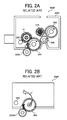
- FIG. 2A is a sectional view of the fixing device 900R.
- the drive input gear 99A receives a driving force f' from a driving gear 200AR of the image forming apparatus
- one part of the force f' is transmitted to the right side plate 97A depicted in FIG. 1B via the support shaft of the drive input gear 99A to lift up the whole fixing device 900R.
- a rotational moment m' is generated around the positioning member 98A due to the lifting force, as illustrated in FIG. 2B .
- the fixing device 900R receives the rotational moment m', the right side plate 97A is twisted and deformed, causing the fixing roller 11R supporting the fixing belt 12R to lose its parallel position with respect to the pressing roller 13R opposing the fixing belt 12R. As a result, the fixing belt 12R may shift from a predetermined position in an axial direction of the fixing roller 11R, thereby generating a crease in the sheet.
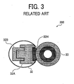
- FIG. 3 is a schematic view of a surf-fixing device 300 illustrating a structure thereof.
- the surf-fixing device 300 includes a fixing belt 32, a pressing roller 33, a ceramic heater 32H, a holder 32A, and a stay 32B.
- the fixing belt 32 is supported by one shaft, not shown, so that the fixing belt 32 easily loses its parallel position with respect to the pressing roller 33, thereby shifting from a predetermined position.
- At least one embodiment provides a fixing device that includes a rotatable fixing member, a pressing member, a drive input rotating body, a first frame, a support shaft, and at least one positioning member.
- the pressing member contacts the fixing member to form a fixing nip therebetween.
- the drive input rotating body receives an external driving force and transmits the driving force to the fixing member.
- the first frame supports the fixing member and the pressing member.
- the support shaft is provided on the first frame to support the drive input rotating body.
- At least one positioning member is supported by an image forming apparatus body when the fixing device is installed in the image forming apparatus body. The positioning member is combined with an end of the support shaft in an axial direction of the support shaft.
- At least one embodiment provides an image forming apparatus that includes a fixing device and a supporting member.
- the fixing device includes a rotatable fixing member, a pressing member, a drive input rotating body, a first frame, a support shaft, and at least one positioning member as described above.
- the supporting member engages the positioning member of the fixing device to support the fixing device.
- spatially relative terms such as “beneath”, “below”, “lower”, “above”, “upper”, and the like, may be used herein for ease of description to describe one element or feature's relationship to another element(s) or feature(s) as illustrated in the figures. It will be understood that the spatially relative terms are intended to encompass different orientations of the device in use or operation in addition to the orientation depicted in the figures. For example, if the device in the figures is turned over, elements described as “below” or “beneath” other elements or features would then be oriented “above” the other elements or features. Thus, term such as “below” can encompass both an orientation of above and below. The device may be otherwise oriented (rotated 90 degrees or at other orientations) and the spatially relative descriptors used herein are interpreted accordingly.
- first, second, etc. may be used herein to describe various elements, components, regions, layers and/or sections, it should be understood that these elements, components, regions, layers and/or sections should not be limited by these terms. These terms are used only to distinguish one element, component, region, layer, or section from another region, layer, or section. Thus, a first element, component, region, layer, or section discussed below could be termed a second element, component, region, layer, or section without departing from the teachings of the present invention.
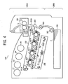
- FIG. 4 is a schematic sectional view of the image forming apparatus 200.
- the image forming apparatus 200 includes an image forming device 200A and a feeding device 200B.
- the image forming device 200A includes a fixing device 100, a transfer belt 202, photoconductors 201Y, 201C, 201M, and 201K, an optical writer 209, a driving roller 201A, a driven roller 201B, and a transfer roller 205.
- the feeding device 200B includes a paper tray 208 and conveyance rollers 206 and 207.
- the fixing device 100 includes a fixing roller 11, a fixing belt 12, and a pressing roller 13.
- the image forming apparatus 200 may be a copier, a facsimile machine, a printer, a multifunction printer having at least one of copying, printing, scanning, and facsimile functions, or the like. According to this non-limiting example embodiment, the image forming apparatus 200 functions as a tandem-type color copier for forming a color image on a recording medium (e.g., a sheet) by electrophotography. However, the image forming apparatus 200 is not limited to the color copier and may form a color and/or monochrome image in other configurations.
- the image forming device 200A is provided in a central portion of the image forming apparatus 200.
- the feeding device 200B is provided below the image forming device 200A.
- the fixing device 100 is incorporated in the image forming device 200A.
- the transfer belt 202 of the image forming device 200A includes a transfer surface extending in a horizontal direction.
- the photoconductors 201Y, 201C, 201M, and 201K, serving as image carriers, are provided side by side to oppose a lower circumferential surface (a transfer surface) of the transfer belt 202, respectively, and form and carry yellow, cyan, magenta, and black toner images having a complementary color relationship.
- the respective photoconductors 201Y, 201C, 201M, and 201K are drum-shaped and rotatable in the same counterclockwise direction.
- a charger, the optical writer 209, a primary transfer device, a development device, and a cleaner are provided around the photoconductors 201Y, 201C, 201M, and 201K, and perform image formation in rotation of the photoconductors 201Y, 201C, 201M, and 201K, respectively.
- the respective development devices store yellow, cyan, magenta, and black toner 2Y, 2C, 2M, and 2K.
- the transfer belt 202 is wrapped around the driving roller 201A and the driven roller 201B to oppose the photoconductors 201Y, 201C, 201M, and 201K and move in the same direction.
- the transfer roller 205 opposes the driven roller 201B.
- a sheet conveyance path from the transfer roller 205 to the fixing device 100 is provided in a vertical direction, the sheet conveyance path may be provided in a lateral direction.
- the paper tray 208 of the feeding device 200B stores sheets P of a recording medium.
- the conveyance rollers 206 and 207 form a conveyance mechanism for separating an uppermost sheet P from other sheets P stored in the paper tray 208 and sequentially conveying each sheet P individually to the transfer roller 205.
- an electrostatic latent image is formed on the photoconductor 201Y based on input image information.
- the development device storing yellow toner develops the electrostatic latent image into a visible yellow toner image.
- the primary transfer device After being supplied with a predetermined bias, the primary transfer device primarily transfers the yellow toner image onto the transfer belt 202.
- cyan, magenta, and black toner images are formed on the photoconductors 201C, 201M, and 201K, respectively and electrostatically transferred and superimposed onto the transfer belt 202 in this order to form a full color toner image.
- the full color toner image transferred from the photoconductors 201Y, 201C, 201M, and 201K onto the transfer belt 202 is then transferred to the sheet P conveyed by the conveyance rollers 206 and 207 and the transfer roller 205.
- the fixing device 100 fixes the toner image on the sheet P at a fixing nip N formed between the fixing belt 12 and the pressing roller 13. For example, when the sheet P passes through the fixing nip N, the fixing roller 11 and the pressing roller 13 are kept parallel to the driven roller 201B and the transfer roller 205, thereby properly fixing the toner image on the sheet P without creasing the sheet P.
- the sheet P discharged from the fixing nip N is fed from the fixing device 100 through a sheet discharge path.
- a separation pawl described later, separates the sheet P from the fixing belt 12, so that the sheet P returns to the discharge path.
- the image forming apparatus 200 since the image forming apparatus 200 includes the fixing device 100, the image forming apparatus 200 can perform high-quality image formation without creasing the sheet P, as is described in detail below.
- FIG. 5 is a schematic sectional view of the fixing device 100.
- the fixing device 100 further includes a cover 100C, a heating roller 14, a thermistor 12A, a separation pawl 16, a tension roller 15A, and a spring 15B.
- the heating roller 14 includes a built-in heater 14H.
- the fixing belt 12 is wrapped around the fixing roller 11 and the heating roller 14 under a predetermined amount of tension.
- the pressing roller 13 rotatably contacts the fixing belt 12 to form the fixing nip N.
- the separation pawl 16 is provided on a sheet discharging side of the fixing nip N, with an edge thereof adjacent to the fixing belt 12, to prevent a sheet P from adhering to the fixing belt 12.
- the fixing belt 12 has a double-layered structure, in which an elastic layer such as a silicone rubber layer is formed over a base material made of nickel, stainless steel, or polyimide, for example.
- the fixing belt 12 may have a three-layer structure in which a releasing layer made of PFA (copolymer of tetrafluoroethylene and perfluoroalkoxyethylene) or PTFE (polytetrafluoroethylene) is formed over the double-layered structure described above.
- the fixing roller 11 includes silicon rubber surrounding a metal core.
- the fixing roller 12 may include foamed silicon rubber so as to prevent absorption of heat of the fixing belt 12.
- the heating roller 14 is hollow and made of aluminum or iron.
- the heater 14H is provided inside the heating roller 14 as a heat source, and may be, but is not necessarily limited to, a halogen heater or the like. Alternatively, the heater 14H may be an IH (induction heating) mechanism.
- the fixing device 100 When the fixing device 100 operates, due to rotation of the pressing roller 13 in a clockwise direction, the fixing belt 12 is driven to rotate in a direction in which the sheet P is discharged (a counterclockwise direction) under an appropriate amount of tension supplied by the tension roller 15A pressing the fixing belt 12 using the spring 15B. In fixation, due to heat generated by the heater 14H provided inside the heating roller 14, the fixing belt 12 is heated to a predetermined temperature, for example, a temperature suitable for toner fixation, detected by the thermistor 12A. It is to be noted that although the fixing device 100 includes the fixing belt 12 serving as a fixing member, alternatively the fixing device 100 may include a roller having a hollow circular cylindrical shape.
- the pressing roller 13 has a cylindrical shape and includes an elastic rubber layer made of silicon rubber or the like provided around a metal core made of aluminum, iron, or the like, and a surface layer including a releasing layer made of PFA or PTFE.
- a pressure device presses the pressing roller 13 against the fixing belt 12 with a predetermined pressure.
- the fixing belt 12 When the fixing belt 12 and the pressing roller 13 are driven to rotate, the fixing belt 12 has a predetermined surface temperature.
- the unfixed toner image passes through the fixing nip N in an upward direction, the unfixed toner image is heated and melted on the sheet P by heat and pressure generated at the fixing nip N, thereby fixing the toner image on the sheet P.
- the edge of the separation pawl 16 contacts a leading edge of the sheet P, thereby separating the sheet P from the fixing belt 12.
- the sheet P discharged from the fixing nip N passes through a predetermined discharge path and is fed from the fixing device 100.
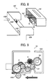
- FIG. 6A is a top view of the fixing device 100 and FIG. 6B is a front view thereof.
- the fixing device 100 further includes side plates 17A and 17B, a bottom plate 17C, a second side plate 17D, a support shaft 18C, positioning members 18A and 18B, a drive input gear 19A, a pressing roller gear 19C, an idler gear 19B, and a drawer connector 20.
- the side plates 17A and 17B are vertically provided on the bottom plate 17C, and support the fixing roller 11, the heating roller 14 depicted in FIG. 5 , and a pressing roller 13 with a bearing.
- the side plates 17A and 17B may be either metal or resin, the side plates 17A and 17B more preferably are metal and stiff.
- the side plates 17A and 17B are reinforced with the bottom plate 17C, stays, and the like, so as to maintain stiffness for holding the respective rollers such that the respective rollers are kept parallel to each other. Together, the side plates 17A and 17B, the bottom plate 17C, and the stays form a frame structure, called a fixing frame.
- the right side plate 17A supports the drive input gear 19A with the support shaft 18C provided in a bottom portion of the fixing device 100 and fixed on the right side plate 17A in an outward direction.
- the drive input gear 19A serving as a drive input rotating body, receives a driving force input from outside, that is, the image forming apparatus 200 depicted in FIG. 4 .
- the fixing device 100 includes the drive input gear 19A
- the fixing device 100 may include a drive transmission mechanism including a coupling and a pulley.
- a rotary shaft of the pressing roller 13 extends outwards from the right side plate 17A.
- the pressing roller gear 19C is provided at one end of the rotary shaft of the pressing roller 13.
- the idler gear 19B is provided between the drive input gear 19A and the pressing roller gear 19C to transmit torque of the drive input gear 19A to the pressing roller gear 19C, and supported by a shaft provided in the right side plate 17A. That is, when the drive input gear 19A receives a driving force transmitted from the image forming apparatus 200 to rotate, rotation of the drive input gear 19A is transmitted to the pressing roller gear 19C via the idler gear 19B to rotate the pressing roller gear 13. As the pressing roller gear 13 rotates, the fixing belt 12 is driven to rotate.
- the drive input gear 19A may directly transmit a driving force to the fixing roller 11 or the heating roller 14 to rotate the fixing roller 11 or the heating roller 14, so as to rotate the fixing belt 12.
- the positioning members 18A and 18B engage supporting members of the image forming apparatus 200 to define a position of the fixing device 100.
- the positioning members 18A and 18B are metallic pins having a circular cylindrical shape.
- the positioning members 18A and 18B may be resin bosses or sheet metal brackets.
- the positioning member 18A is provided at one end of the support shaft 18C opposite to the other end thereof provided on the right side plate 17A (in the vicinity of the cover 100C) and combined with the support shaft 18C, so that the positioning member 18A extends from the cover 100C. That is, an outer portion of a member combining the positioning member 18A and the support shaft 18C provided outside the cover 100C is defined as a positioning member, and an inner portion thereof provided inside the cover 100C is defined as a support shaft.
- the positioning member 18B is provided perpendicular to the right side plate 97B and fixed thereon, with an end of the positioning member 18B in an axial direction of the positioning member 18B extending from the cover 100C. Central axes of the positioning members 18A and 18B are coaxial with a rotation center of the drive input gear 19A, respectively.
- the positioning member 18A combining with the support shaft 18C has a circular cylindrical shape and is coaxial with the support shaft 18C.
- one end of a common cylindrical shaft of the positioning member 18A and the support shaft 18C extends from the cover 100C and the other end thereof is provided perpendicular to the right side plate 17A. Therefore, since the positioning member 18A has a cylindrical shape, and the central axis thereof is coaxial with a rotation center of the drive input gear 19A, a single component combines both the positioning member 18A and the support shaft 18C of the drive input gear 19A. As a result, the number of components can be reduced, thereby providing a compact fixing device 100 at lower cost.
- the second side plate 17D supports an end portion of the support shaft 18C to which the positioning member 18A is attached.
- the positioning member 18A combined with the support shaft 18C inclines, causing the respective rollers of the fixing device 100 to incline.
- the respective rollers of the fixing device 100 are not parallel to sheet conveyance rollers, that is, the transfer roller 205 and the conveyance rollers 206 and 207 of the image forming apparatus 200 depicted in FIG. 4 , thereby generating a crease in the sheet P to cause a faulty image.
- the drive input gear 19A is sandwiched between the right side plate 17A and the second side plate 17D, both ends of the support shaft 18C of the drive input gear 19A are supported by the right side plate 17A and the second side plate 17D, respectively, thereby preventing the positioning member 18A combined with the support shaft 18C from inclining with respect to the right side plate 17A of the fixing frame, so that the respective rollers of the fixing device 100 are kept parallel to the sheet conveyance rollers of the image forming apparatus 200, thereby preventing generation of a crease in the sheet P passing through the fixing nip N.
- FIG. 7A is a perspective view of the fixing device 100 and the image forming apparatus 200.
- FIG. 7B is a sectional view of the fixing device 100 and the image forming apparatus 200.
- the image forming apparatus 200 further includes a body frame 200F and a drive transmission gear 200D.
- the body frame 200F includes positioning grooves 200C.
- a user moves the fixing device 100 in a direction perpendicular to shaft lines of the positioning members 18A and 18B and installs the fixing device 100 in a predetermined position of the image forming apparatus 200, with a surface of the fixing device 100 on which the drawer connector 20 is provided facing toward the back of the image forming apparatus 200.
- the body frame 200F incorporates the transfer roller 205 and the photoconductors 201Y, 201C, 201M, and 201K depicted in FIG. 4 .
- the positioning grooves 200C serving as supporting members, are cut into the body frame 200F.
- the fixing device 100 is attached to the image forming apparatus 200, the user can slide the positioning members 18A and 18B from front to rear using the positioning groove 200C as guide rails. Then, by engaging the positioning members 18A and 18B with end portions of the positioning grooves 200C, respectively, the fixing device 100 is installed in the predetermined position of the image forming apparatus 200.
- the fixing device 100 is properly positioned relative to the transfer roller 205, the photoconductors 201Y, 201C, 201M, and 201K, and a registration roller for feeding the sheet P. That is, according to this example embodiment, shaft lines of the positioning members 18A and 18B of the fixing device 100 are parallel to the transfer roller 205 and the registration roller of the image forming apparatus 200, and the respective rollers of the fixing device 100 are kept parallel to the shaft lines of the positioning members 18A and 18B, thereby properly conveying the sheet P to the fixing device 100.
- a holding lever made of resin fixes the positioning members 18A and 18B, so as to engage the positioning members 18A and 18B with the positioning grooves 200C.
- a screw clamp may be used.
- the drive transmission gear 200D is provided below the positioning groove 200C of the body frame 200F.
- the drive transmission gear 200D engages the drive input gear 19A to transmit a driving force from the drive transmission gear 200A to the drive input gear 19A.
- FIG. 8 is a schematic perspective view of the fixing device 100' and an image forming apparatus 200'.
- the fixing device 100' includes positioning members 18A' and 18B'.
- the image forming apparatus 200' includes positioning holes 200E.
- the positioning members 18A and 18B depicted in FIG. 7A extend in a width direction of the fixing device 100
- the positioning members 18A' and 18B' extend from a surface of the fixing device 100' in a direction of insertion of the fixing device 100' into the image forming apparatus 200' (a surface on which the drawer connector 20 is provided).
- a support shaft is provided inside the fixing device 100' and combined with the positioning member 18A' to support a worm gear-type drive input gear.
- the positioning holes 200E serving as supporting members, engage the positioning members 18A' and 18B' to guide the positioning members 18A' and 18B' to the body frame 200F.
- FIG. 9 is a sectional view of the fixing device 100 when attached to the image forming apparatus 200.
- the drive input gear 19A receives a driving force f from the drive transmission gear 200A of the image forming apparatus 200
- one part of the received force of the drive input gear 19A acts on the support shaft 18C of the drive input gear 19A and the positioning member 18A depicted in FIG. 6A .
- the positioning member 18A is supported by the positioning groove 200C, depicted in FIG. 7A , of the image forming apparatus 200, no rotational moment m' described above with reference to FIG. 2B is generated, thereby preventing deformation of the side plates 17A and 17B of the fixing device 100 depicted in FIG. 6A .
- the positioning members 18A and 18B depicted in FIG. 7A are inserted into the positioning groove 200C depicted in FIG. 7A in a direction S substantially identical to a direction of a driving force f acting on the drive input gear 19A.
- the positioning member 18A is supplied with a force in a direction opposite to a direction in which the fixing device 100 approaches the image forming apparatus 200, thereby generating a backlash between the image forming apparatus 200 and the body frame 200F, thus causing the fixing device 100 to shift from the predetermined position in a direction in which the fixing device 100 is detached from the image forming apparatus 200, or causing the side plates 17A and 17B, serving as a frame, to be deformed.
- the positioning member 18A contacts the end portion of the positioning groove 200C of the body frame 200F, thereby preventing generation of a backlash between the image forming apparatus 200 and the body frame 200F.
- the fixing device 100 receives a driving force from the image forming apparatus 200, the fixing device 100 is kept in a proper position in the image forming apparatus 200, thereby preventing a failure of conveyance (generation of creases) of a transfer material, that is, the sheet P, due to lack of parallel alignment between the respective rollers of the fixing device 100 and sheet conveyance rollers of the image forming apparatus 200.
- the fixing roller 11 can be properly positioned relative to the image forming apparatus 200, so that the sheet P is stably fed to the fixing device 100, thereby preventing generation of a crease in the sheet P as well as preventing a shift of the fixing belt 12 depicted in FIG. 6A in the axial direction of the fixing belt 12.
- FIG. 10 is a schematic sectional view of the fixing device 100A.
- the fixing device 100A includes a fixing roller R12, rollers R11, R14, and R15, a pressing belt 13A, and a reinforcement member 13B.
- the fixing roller R12 includes a built-in heater 12H.
- the pressing belt 13A also includes a built-in heater 13H.
- the fixing roller R12 serving as a fixing member, is rotatably provided in an upper portion of the fixing device 100A.
- the pressing belt 13A serving as a pressing member, is provided under the fixing roller R12 and wrapped around the rollers R11, R14, and R15, and rotate in a direction A.
- the reinforcement member 13B serving as a pressure pad, is provided on an inner surface of the pressing belt 13A.
- the fixing roller R12 contacts the pressing belt 13A to form a fixing nip N' therebetween.
- the fixing roller R12 is heated by the heater 12H as a heat source, and the pressing belt 13A is heated by the heater 13H as a heat source.
- the pressing belt 13A serving as a pressing member
- the pressing belt 13A is a belt instead of a roller, and that both the fixing roller and the pressing belt each has a built-in heater, for better heating.
- FIG. 11 is a schematic sectional view of the fixing device 100B.
- the fixing device 100B includes a fixing belt 12A, a pressing belt 13C, rollers R16, R17, R18, and R19, guide members 12G and 13G, and heaters 12H' and 13H'.
- the fixing belt 12A serving as a fixing member, is wrapped around the rollers R16 and R17 and the guide member 12G. As the roller R17 is driven to rotate by a driving member, the fixing belt 12A rotates.
- the pressing belt 13C serving as a pressing member, is wrapped around the rollers R18 and R19 and the guide member 13G.
- the roller R18 opposes the roller R16 to press the pressing belt 13C and the fixing belt 12A against the roller R16.
- the roller R18 is driven to rotate at a peripheral speed equal to that of the roller R16.
- the heaters 12H' and 13H' are provided inside the rollers R16 and R18 to heat the rollers R16 and R18, respectively, thereby heating the fixing belt 12A and the pressing belt 13C.
- the fixing device 100 depicted in FIG. 5 and the fixing device 100' depicted in FIG. 8 do not need any dedicated members designed to prevent the shift of the fixing belt 12, and thus the fixing devices 100 and 100' can be made more compact and component costs decreased. Due to the decrease in the number of components, warm-up time of the fixing devices 100 and 100' can be shortened.
- the structure of the fixing device 100 prevents deformation of the side plates 17A and 17B depicted in FIG. 6A , the pressing roller 13 depicted in FIG. 5 is kept parallel to the fixing roller 11 and the heating roller 14 supporting the fixing belt 12 depicted in FIG. 5 . Therefore, even a fixing device using the surf-fixing method depicted in FIG. 3 can reduce and prevent shifting of a fixing belt. Further, according to the example embodiment, the fixing belt 12 and the pressing roller 13 of the fixing device 100 does not have a decreased frictional coefficient. Thus, when the fixing belt 12 is driven to rotate due to rotation of the pressing roller 13, the fixing belt 12 is prevented from slipping on the pressing roller 13.
- the drive input gear 19A is stably positioned in the fixing device 100, the central axis of the drive input gear 19A keeps a proper distance from the central axis of a gear contacting the drive input gear 19A, for example, the idler gear 19B depicted in FIG. 9 or the drive transmission gear 200D depicted in FIG. 9 , thereby preventing uneven wearing of the drive input gear 19A as well as decreasing abnormal noise of the gear, so that the fixing device 100 has a longer service life than that of a conventional fixing device.
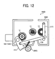
- a conventional fixing device uses a pressure release mechanism of a pressing roller, thereby easily removing a sheet jammed at a fixing nip by controlling a width of the nip. That is, when a driving force is transmitted from an image forming apparatus to the fixing device, a cam or the like rotates, thereby changing a pressing force of the pressing roller. When doing so, the force transmitted from the image forming apparatus causes the same problem as described above with reference to FIG. 2B when the drive input gear 99A receives the driving force f'. Therefore, according to this example embodiment, a driving force transmitted from the image forming apparatus 200 is received by a member supported by a support shaft combined with a positioning member of the fixing device 100. FIGS. 12 , 13, and 14 illustrate an embodiment of such an arrangement.
- FIG. 12 is a schematic sectional view of the fixing device 100D and FIG. 13 is a schematic front view of the fixing device 100D.
- FIG. 14 is a schematic front view of the fixing device 100D'.
- the fixing device 100D includes a fan-like gear 21A, a linkage 21B, a pressure lever 21C, and a pressure regulator gear 200G. As illustrated in FIG. 13 , the fixing device 100D further includes support axes 18C and 18D.
- the fan-like gear 21A is provided on the support shaft 18C (18D) coaxial with the positioning member 18A (18B). Upon receipt of a driving force fA from the pressure regulator gear 200G provided in the image forming apparatus 200 depicted in FIG. 4 , the fan-like gear 21A swings.
- the linkage 21B is rotatably connected to the fan-like gear 21A.
- the pressure lever 21C is rotatably connected to the linkage 21B. Together, the fan-like gear 21A, the linkage 21B, the pressure lever 21C, and the pressure regulator gear 200D form a pressure release mechanism for releasing a pressing force of the pressing roller 13.
- the fan-like gear 21A Upon receipt of the driving force from the pressure regulator gear 200G, the fan-like gear 21A cause the linkage 21B to move the pressure lever 21C. As the fan-like gear 21A rotates clockwise, the linkage 21B is pulled by the fan-like gear 21A to draw the pressure lever 21C to a pressing position. Conversely, when the fan-like gear 21A rotates counterclockwise, the pressure lever 21C moves to a pressure releasing position.
- the fan-like gear 21A serving as a drive transmission member, receives a driving force, other than the driving force of the fixing belt 12, from the image forming apparatus 200.
- the support shaft 18D serving as a second support shaft, supports the fan-like gear 21A.
- the positioning member 18B is provided at an end of the support shaft 18D to combine with the support shaft 18D. Therefore, the support shaft 18D combined with the positioning member 18B supports the fan-like gear 21A, thereby preventing deformation of the side plates 17A and 17B, serving as a first frame.
- the support shaft 18D combined with the positioning member 18B receives one part of the driving force transmitted from the image forming apparatus 200, if the driving force is great, a deformation moment m acts on the side plates 17A and 17B, as illustrated in FIG. 13 , to twist the side plates 17A and 17B to cause deformation of the side plates 17A and 17B. Therefore, as illustrated in FIG. 14 , the support shaft 18C combined with the positioning member 18A receives both a driving force Y received by the drive input gear 19A and a force X (a pressure releasing force) received by the fan-like gear 21A.
- the fan-like gear 21A serving as a drive transmission member, receives a driving force, other than the driving force of the fixing belt 12, from the image forming apparatus 200, and is supported by the support shaft 18C supporting the drive input gear 19A, serving as a drive input rotating body. That is, the fan-like gear 21A for releasing a pressing force of the pressing roller 13 is adjacent to the drive input gear 19A in a width direction of the fixing device 100D', so that the support shaft 18C supports both the fan-like gear 21A and the drive input gear 19A. Therefore, for example, as illustrated in FIG.
- both the forces combine with each other in the support shaft 18C without being transmitted to the side plates 17A and 17B, that is, both forces cancel each other out, thereby preventing generation of the moment m causing deformation of the side plates 17A and 17B.
- the fixing belt 12R shifted from a predetermined position in an axial direction of the fixing belt 12R at a velocity of 0.6 mm/s.
- the fixing belt 12 did not shift from a predetermined position in the axial direction of the fixing belt 12, or at most the fixing belt 12 shifted from the predetermined position at a velocity of 0.1 mm/s at a maximum, not greater than one-sixth of the velocity seen in the fixing device 900R, thereby preventing or at least substantially preventing a shift of the fixing belt 12 in the axial direction of the fixing belt 12.
Landscapes
- Physics & Mathematics (AREA)
- General Physics & Mathematics (AREA)
- Fixing For Electrophotography (AREA)
- Electrophotography Configuration And Component (AREA)
Applications Claiming Priority (2)
| Application Number | Priority Date | Filing Date | Title |
|---|---|---|---|
| JP2008090817 | 2008-03-31 | ||
| JP2008240574A JP5552732B2 (ja) | 2008-03-31 | 2008-09-19 | 定着装置及び画像形成装置 |
Publications (3)
| Publication Number | Publication Date |
|---|---|
| EP2107431A2 true EP2107431A2 (fr) | 2009-10-07 |
| EP2107431A3 EP2107431A3 (fr) | 2010-04-21 |
| EP2107431B1 EP2107431B1 (fr) | 2018-10-24 |
Family
ID=40792886
Family Applications (1)
| Application Number | Title | Priority Date | Filing Date |
|---|---|---|---|
| EP09250840.7A Active EP2107431B1 (fr) | 2008-03-31 | 2009-03-25 | Dispositif de fixation et appareil de formation d'images |
Country Status (4)
| Country | Link |
|---|---|
| US (1) | US7983598B2 (fr) |
| EP (1) | EP2107431B1 (fr) |
| JP (1) | JP5552732B2 (fr) |
| CN (1) | CN101551629B (fr) |
Families Citing this family (79)
| Publication number | Priority date | Publication date | Assignee | Title |
|---|---|---|---|---|
| JP5387884B2 (ja) * | 2008-10-14 | 2014-01-15 | 株式会社リコー | 定着装置及び画像形成装置 |
| JP5170842B2 (ja) * | 2008-10-14 | 2013-03-27 | 株式会社リコー | 定着装置及び画像形成装置 |
| JP5201478B2 (ja) * | 2009-02-09 | 2013-06-05 | 株式会社リコー | 定着装置及び画像形成装置 |
| JP5091885B2 (ja) | 2009-02-12 | 2012-12-05 | 株式会社リコー | 定着装置及び画像形成装置 |
| JP5348561B2 (ja) * | 2009-05-15 | 2013-11-20 | 株式会社リコー | 定着装置及び画像形成装置 |
| JP5464411B2 (ja) * | 2009-07-29 | 2014-04-09 | 株式会社リコー | 定着装置及び画像形成装置 |
| JP2011043666A (ja) * | 2009-08-21 | 2011-03-03 | Ricoh Co Ltd | 定着装置および画像形成装置 |
| JP5321905B2 (ja) * | 2009-09-01 | 2013-10-23 | 株式会社リコー | 定着装置及び画像形成装置 |
| JP5582455B2 (ja) * | 2009-09-03 | 2014-09-03 | 株式会社リコー | 定着装置および画像形成装置 |
| JP5556343B2 (ja) * | 2009-09-03 | 2014-07-23 | 株式会社リコー | 定着装置および画像形成装置 |
| JP5366005B2 (ja) | 2009-09-10 | 2013-12-11 | 株式会社リコー | 定着装置および画像形成装置 |
| JP5299690B2 (ja) * | 2009-09-10 | 2013-09-25 | 株式会社リコー | 定着装置及び画像形成装置 |
| JP5549160B2 (ja) * | 2009-09-10 | 2014-07-16 | 株式会社リコー | 定着装置及び画像形成装置 |
| JP2011064726A (ja) | 2009-09-15 | 2011-03-31 | Ricoh Co Ltd | 定着装置および画像形成装置 |
| JP2011064767A (ja) * | 2009-09-15 | 2011-03-31 | Ricoh Co Ltd | 定着装置及び画像形成装置 |
| JP5440922B2 (ja) * | 2009-09-28 | 2014-03-12 | 株式会社リコー | 定着装置および画像形成装置 |
| JP5472605B2 (ja) * | 2009-10-09 | 2014-04-16 | 株式会社リコー | 定着装置及び画像形成装置 |
| JP5440777B2 (ja) * | 2009-11-17 | 2014-03-12 | 株式会社リコー | 定着装置および画像形成装置 |
| JP5532977B2 (ja) | 2009-11-30 | 2014-06-25 | 株式会社リコー | 定着装置及び画像形成装置 |
| JP5403264B2 (ja) * | 2010-01-13 | 2014-01-29 | 株式会社リコー | 定着装置及び画像形成装置 |
| JP5381746B2 (ja) | 2010-01-26 | 2014-01-08 | 株式会社リコー | 定着装置及び画像形成装置 |
| US8600276B2 (en) * | 2010-01-27 | 2013-12-03 | Ricoh Company, Limited | Heat conduction unit, fixing device, and image forming apparatus |
| JP5445188B2 (ja) * | 2010-02-07 | 2014-03-19 | 株式会社リコー | 定着装置及び画像形成装置 |
| JP5445189B2 (ja) | 2010-02-08 | 2014-03-19 | 株式会社リコー | 定着装置及び画像形成装置 |
| JP5564981B2 (ja) | 2010-02-25 | 2014-08-06 | 株式会社リコー | 定着装置及び画像形成装置 |
| JP5418913B2 (ja) * | 2010-03-04 | 2014-02-19 | 株式会社リコー | 定着装置及び画像形成装置 |
| JP5600970B2 (ja) | 2010-03-08 | 2014-10-08 | 株式会社リコー | 定着装置および画像形成装置 |
| JP5440278B2 (ja) | 2010-03-10 | 2014-03-12 | 株式会社リコー | 定着装置および画像形成装置 |
| JP5633386B2 (ja) | 2010-03-10 | 2014-12-03 | 株式会社リコー | 定着装置及び画像形成装置 |
| JP5408553B2 (ja) | 2010-03-12 | 2014-02-05 | 株式会社リコー | 定着装置及び画像形成装置 |
| JP5625406B2 (ja) * | 2010-03-16 | 2014-11-19 | 株式会社リコー | 画像形成装置 |
| JP5589526B2 (ja) * | 2010-03-18 | 2014-09-17 | 株式会社リコー | 定着装置及び画像形成装置 |
| JP2011197183A (ja) * | 2010-03-18 | 2011-10-06 | Ricoh Co Ltd | 定着装置及び画像形成装置 |
| JP5510721B2 (ja) | 2010-05-07 | 2014-06-04 | 株式会社リコー | 定着装置及び画像形成装置 |
| CN104898391A (zh) * | 2010-05-13 | 2015-09-09 | 夏普株式会社 | 定影装置和具备它的图像形成装置 |
| JP5510058B2 (ja) | 2010-05-19 | 2014-06-04 | 株式会社リコー | 画像形成装置 |
| JP5499999B2 (ja) | 2010-08-31 | 2014-05-21 | 株式会社リコー | 画像形成装置 |
| JP5625865B2 (ja) | 2010-12-16 | 2014-11-19 | 株式会社リコー | 定着装置及び画像形成装置 |
| JP5589820B2 (ja) | 2010-12-17 | 2014-09-17 | 株式会社リコー | 定着装置及び画像形成装置 |
| JP5640750B2 (ja) | 2011-01-07 | 2014-12-17 | 株式会社リコー | 定着装置、画像形成装置、定着制御方法 |
| JP5825545B2 (ja) | 2011-01-11 | 2015-12-02 | 株式会社リコー | 定着装置および画像形成装置 |
| JP2012185295A (ja) | 2011-03-04 | 2012-09-27 | Ricoh Co Ltd | 定着装置および画像形成装置 |
| JP5768507B2 (ja) | 2011-03-17 | 2015-08-26 | 株式会社リコー | 定着装置および画像形成装置 |
| JP5773151B2 (ja) | 2011-08-17 | 2015-09-02 | 株式会社リコー | 定着装置及び画像形成装置 |
| JP5298171B2 (ja) * | 2011-08-23 | 2013-09-25 | シャープ株式会社 | 現像装置および画像形成装置 |
| JP5737629B2 (ja) | 2011-12-26 | 2015-06-17 | 株式会社リコー | 定着装置及び画像形成装置 |
| JP6136220B2 (ja) | 2011-12-27 | 2017-05-31 | 株式会社リコー | 定着装置、及び、画像形成装置 |
| JP6136221B2 (ja) | 2011-12-27 | 2017-05-31 | 株式会社リコー | 定着装置、及び、画像形成装置 |
| CN103186087B (zh) | 2011-12-28 | 2016-08-03 | 株式会社理光 | 定影装置、成像装置和分离构件 |
| JP5796711B2 (ja) | 2011-12-28 | 2015-10-21 | 株式会社リコー | 定着装置及び画像形成装置 |
| JP5904325B2 (ja) | 2011-12-28 | 2016-04-13 | 株式会社リコー | 定着装置及び画像形成装置 |
| JP5928783B2 (ja) | 2012-01-11 | 2016-06-01 | 株式会社リコー | 定着装置および画像形成装置 |
| JP5737520B2 (ja) | 2012-01-13 | 2015-06-17 | 株式会社リコー | 定着装置及び画像形成装置 |
| JP5761524B2 (ja) | 2012-01-13 | 2015-08-12 | 株式会社リコー | 定着装置及び画像形成装置 |
| JP5796714B2 (ja) | 2012-01-13 | 2015-10-21 | 株式会社リコー | 定着装置及び画像形成装置 |
| JP5970828B2 (ja) * | 2012-01-19 | 2016-08-17 | 株式会社リコー | 分離部材、定着装置、及び画像形成装置 |
| JP5967468B2 (ja) | 2012-01-24 | 2016-08-10 | 株式会社リコー | 定着装置、及び、画像形成装置 |
| JP5943231B2 (ja) | 2012-01-26 | 2016-07-05 | 株式会社リコー | 定着装置、及び、画像形成装置 |
| JP6035668B2 (ja) | 2012-01-27 | 2016-11-30 | 株式会社リコー | 定着装置、及び、画像形成装置 |
| JP6051741B2 (ja) | 2012-01-31 | 2016-12-27 | 株式会社リコー | 定着装置および画像形成装置 |
| JP5963105B2 (ja) | 2012-02-02 | 2016-08-03 | 株式会社リコー | 定着装置及び画像形成装置 |
| JP5850326B2 (ja) | 2012-02-09 | 2016-02-03 | 株式会社リコー | 定着装置および画像形成装置 |
| JP6003619B2 (ja) | 2012-02-09 | 2016-10-05 | 株式会社リコー | 定着装置及び画像形成装置 |
| JP6423994B2 (ja) | 2012-02-09 | 2018-11-14 | 株式会社リコー | 定着装置及び画像形成装置 |
| JP6209311B2 (ja) | 2012-02-09 | 2017-10-04 | 株式会社リコー | 定着装置及び画像形成装置 |
| US9026024B2 (en) | 2012-02-09 | 2015-05-05 | Ricoh Company, Ltd. | Fixing device capable of minimizing damage of endless rotary body and image forming apparatus incorporating same |
| JP6103679B2 (ja) | 2012-02-09 | 2017-03-29 | 株式会社リコー | 定着装置及び画像形成装置 |
| JP6201312B2 (ja) | 2012-02-09 | 2017-09-27 | 株式会社リコー | 画像形成装置 |
| JP5950152B2 (ja) | 2012-03-22 | 2016-07-13 | 株式会社リコー | 定着装置、及び、画像形成装置 |
| JP5958014B2 (ja) * | 2012-03-29 | 2016-07-27 | 富士ゼロックス株式会社 | 画像形成装置、定着部保持機構、および定着装置 |
| JP5659249B2 (ja) * | 2013-01-31 | 2015-01-28 | 株式会社東芝 | シート処理装置 |
| JP6131412B2 (ja) * | 2014-03-20 | 2017-05-24 | コニカミノルタ株式会社 | 定着装置 |
| JP6477145B2 (ja) * | 2015-03-30 | 2019-03-06 | コニカミノルタ株式会社 | 定着装置および画像形成装置 |
| JP7447642B2 (ja) * | 2019-07-10 | 2024-03-12 | 富士フイルムビジネスイノベーション株式会社 | 定着装置、画像形成装置 |
| JP7570824B2 (ja) * | 2020-05-12 | 2024-10-22 | キヤノン株式会社 | 定着装置 |
| EP4155832B1 (fr) * | 2020-05-20 | 2025-08-20 | KYOCERA Document Solutions Inc. | Dispositif de formation d'image |
| US12013652B2 (en) | 2022-03-17 | 2024-06-18 | Ricoh Company, Ltd. | Heating device, fixing device, and image forming apparatus including a rotator holder and reflector |
| CN117706892B (zh) * | 2022-09-09 | 2026-04-03 | 柯尼卡美能达株式会社 | 定影器驱动装置、定影装置以及图像形成装置 |
| JP2024049951A (ja) * | 2022-09-29 | 2024-04-10 | 京セラドキュメントソリューションズ株式会社 | 定着装置及び画像形成装置 |
Citations (1)
| Publication number | Priority date | Publication date | Assignee | Title |
|---|---|---|---|---|
| JP2008240574A (ja) | 2007-03-26 | 2008-10-09 | Jtekt Corp | 遠心圧縮機 |
Family Cites Families (63)
| Publication number | Priority date | Publication date | Assignee | Title |
|---|---|---|---|---|
| US4110068A (en) * | 1977-02-22 | 1978-08-29 | International Business Machines Corporation | Hot roller fuser having manually operable jam clearance mechanism |
| JPH049962U (fr) * | 1990-05-16 | 1992-01-28 | ||
| JP2538376Y2 (ja) | 1990-10-02 | 1997-06-11 | バンドー化学株式会社 | ベルト駆動装置 |
| US5250270A (en) | 1992-07-17 | 1993-10-05 | The M. W. Kellogg Company | Catalytic reactor bed |
| US5559593A (en) | 1994-05-13 | 1996-09-24 | Ricoh Company, Ltd. | Cleaning device for an image forming apparatus |
| JP2761197B2 (ja) * | 1995-04-28 | 1998-06-04 | 株式会社リコー | クリーニングトナーマガジンおよび画像形成装置 |
| JPH1069155A (ja) | 1996-05-29 | 1998-03-10 | Ricoh Co Ltd | 画像形成装置 |
| JPH1073976A (ja) | 1996-07-03 | 1998-03-17 | Ricoh Co Ltd | 画像形成装置 |
| JP3537116B2 (ja) | 1996-11-01 | 2004-06-14 | 株式会社リコー | 画像形成装置 |
| US6026273A (en) * | 1997-01-28 | 2000-02-15 | Kabushiki Kaisha Toshiba | Induction heat fixing device |
| KR100370539B1 (ko) | 1997-04-03 | 2005-01-15 | 가부시키가이샤 리코 | 화상형성장치및방법 |
| JPH1124434A (ja) * | 1997-06-30 | 1999-01-29 | Ricoh Co Ltd | 駆動接離機構 |
| JPH11338212A (ja) | 1998-03-25 | 1999-12-10 | Ricoh Co Ltd | 画像形成装置 |
| JP3753862B2 (ja) | 1998-03-26 | 2006-03-08 | 株式会社リコー | 画像形成装置 |
| KR100327956B1 (ko) | 1998-06-08 | 2002-03-16 | 이토가 미찌야 | 개선된 전사장치, 방법 및 상기 전사장치 혹은 방법을 사용하는 화상형성장치 |
| JP3577228B2 (ja) | 1998-10-16 | 2004-10-13 | 株式会社リコー | 画像形成装置およびこれに用いる作像ユニット |
| JP2000147978A (ja) * | 1998-11-09 | 2000-05-26 | Toshiba Corp | 画像形成装置 |
| JP3588029B2 (ja) | 1999-04-09 | 2004-11-10 | 株式会社リコー | 電子写真式画像形成装置およびそれに用いるプロセスカートリッジ |
| JP2001005240A (ja) * | 1999-06-18 | 2001-01-12 | Canon Inc | 電子写真画像形成装置 |
| JP2001027852A (ja) | 1999-07-14 | 2001-01-30 | Ricoh Co Ltd | 画像形成装置 |
| JP2001092208A (ja) | 1999-09-22 | 2001-04-06 | Ricoh Co Ltd | カラー画像形成装置 |
| JP3825600B2 (ja) | 2000-01-13 | 2006-09-27 | 株式会社リコー | 帯電装置、画像形成装置、像担持体ユニット及び荷電ローラ |
| JP3844658B2 (ja) | 2000-02-08 | 2006-11-15 | 株式会社リコー | 荷電ローラ、帯電装置、像担持体ユニット、画像形成装置及び荷電ローラへのフィルム材巻付方法 |
| JP2001265099A (ja) | 2000-03-17 | 2001-09-28 | Ricoh Co Ltd | 画像形成装置 |
| EP1925986B1 (fr) | 2000-04-07 | 2009-12-30 | Ricoh Company, Ltd. | Procédés pour fabriquer un appareil de formation d'images |
| JP3795770B2 (ja) | 2000-06-30 | 2006-07-12 | 株式会社リコー | 定着装置および画像形成装置 |
| JP2002173212A (ja) | 2000-09-28 | 2002-06-21 | Ricoh Co Ltd | ベルト駆動装置、定着装置及び画像形成装置 |
| JP3957968B2 (ja) | 2000-11-24 | 2007-08-15 | 株式会社リコー | 定着装置及びこれを有する画像形成装置 |
| JP3708826B2 (ja) | 2001-01-23 | 2005-10-19 | 株式会社リコー | ベルト駆動装置及びベルト定着装置及び画像形成装置 |
| JP3880424B2 (ja) | 2001-03-29 | 2007-02-14 | 株式会社リコー | 画像形成装置 |
| JP2002372885A (ja) | 2001-06-18 | 2002-12-26 | Ricoh Co Ltd | 液体塗布装置および画像形成装置 |
| JP2003076189A (ja) | 2001-06-22 | 2003-03-14 | Ricoh Co Ltd | 定着装置および画像形成装置 |
| JP3691026B2 (ja) | 2002-04-12 | 2005-08-31 | 株式会社リコー | 定着装置及び画像形成装置 |
| JP4099098B2 (ja) | 2002-05-31 | 2008-06-11 | 株式会社リコー | 定着装置・画像形成装置 |
| JP2004340997A (ja) * | 2003-05-13 | 2004-12-02 | Fuji Xerox Co Ltd | 定着ユニットの脱着機構 |
| US7151907B2 (en) | 2003-07-30 | 2006-12-19 | Ricoh Company Limited | Fixing device, image forming apparatus using the same and process cartridge |
| JP4439885B2 (ja) | 2003-11-25 | 2010-03-24 | 株式会社リコー | 定着装置及び画像形成装置 |
| JP2005189461A (ja) | 2003-12-25 | 2005-07-14 | Ricoh Co Ltd | ベルト定着装置,画像形成装置及びその画像形成装置において使用するトナー |
| JP2005316080A (ja) | 2004-04-28 | 2005-11-10 | Ricoh Co Ltd | ローラ及びそのローラを用いる定着装置並びに画像形成装置 |
| US7406276B2 (en) * | 2004-06-30 | 2008-07-29 | Oki Data Corporation | Contact pressure setting method and image forming apparatus |
| JP4732027B2 (ja) | 2004-06-30 | 2011-07-27 | 株式会社リコー | 定着装置及び画像形成装置 |
| JP4902955B2 (ja) * | 2004-11-25 | 2012-03-21 | 株式会社リコー | 定着装置、画像形成装置および定着装置の製造方法 |
| JP2006154487A (ja) | 2004-11-30 | 2006-06-15 | Ricoh Co Ltd | 定着装置、画像形成装置及び定着装置の制御方法 |
| JP2006163305A (ja) * | 2004-12-10 | 2006-06-22 | Fuji Xerox Co Ltd | 画像形成装置 |
| JP2006201564A (ja) | 2005-01-21 | 2006-08-03 | Ricoh Co Ltd | 定着装置および画像形成装置 |
| JP4883914B2 (ja) | 2005-01-24 | 2012-02-22 | 株式会社リコー | 定着装置及びこれを用いる画像形成装置 |
| US20060257183A1 (en) | 2005-05-12 | 2006-11-16 | Masanao Ehara | Image forming apparatus |
| JP4689370B2 (ja) | 2005-06-30 | 2011-05-25 | 株式会社リコー | 定着装置および画像形成装置 |
| JP4654809B2 (ja) * | 2005-07-21 | 2011-03-23 | 富士ゼロックス株式会社 | 定着装置及び画像形成装置 |
| JP4798699B2 (ja) | 2005-09-12 | 2011-10-19 | 株式会社リコー | 画像形成装置、およびその定着制御方法 |
| JP2007079187A (ja) | 2005-09-15 | 2007-03-29 | Ricoh Co Ltd | 画像形成装置 |
| JP2007139882A (ja) | 2005-11-15 | 2007-06-07 | Ricoh Co Ltd | 画像形成方法および画像形成装置 |
| JP2007206265A (ja) | 2006-01-31 | 2007-08-16 | Ricoh Co Ltd | 定着装置及び画像形成装置 |
| JP4921035B2 (ja) * | 2006-05-16 | 2012-04-18 | キヤノン株式会社 | 画像形成装置 |
| JP4818826B2 (ja) | 2006-06-19 | 2011-11-16 | 株式会社リコー | 定着装置および画像形成装置 |
| JP2008065264A (ja) | 2006-09-11 | 2008-03-21 | Ricoh Co Ltd | 定着装置及び画像形成装置 |
| US8116670B2 (en) | 2006-11-14 | 2012-02-14 | Ricoh Company, Ltd. | Fixing device and image forming apparatus using the same |
| EP1927902B1 (fr) | 2006-11-28 | 2015-10-14 | Ricoh Company, Ltd. | Dispositif de fixation et appareil de formation d'images comprenant celui-ci |
| JP4999444B2 (ja) | 2006-12-20 | 2012-08-15 | 株式会社リコー | 定着装置及び画像形成装置 |
| JP5163931B2 (ja) | 2007-03-08 | 2013-03-13 | 株式会社リコー | 定着装置及び画像形成装置 |
| JP2008261953A (ja) | 2007-04-10 | 2008-10-30 | Ricoh Co Ltd | 画像形成装置 |
| US8428499B2 (en) | 2007-05-22 | 2013-04-23 | Ricoh Company, Ltd. | Image forming apparatus, and fixing apparatus having a heating member to heat a fixing member |
| US8244168B2 (en) | 2007-06-25 | 2012-08-14 | Ricoh Company, Ltd. | Image forming apparatus with movable transfer device |
-
2008
- 2008-09-19 JP JP2008240574A patent/JP5552732B2/ja active Active
-
2009
- 2009-03-25 EP EP09250840.7A patent/EP2107431B1/fr active Active
- 2009-03-30 CN CN2009101282837A patent/CN101551629B/zh active Active
- 2009-03-31 US US12/385,101 patent/US7983598B2/en not_active Expired - Fee Related
Patent Citations (1)
| Publication number | Priority date | Publication date | Assignee | Title |
|---|---|---|---|---|
| JP2008240574A (ja) | 2007-03-26 | 2008-10-09 | Jtekt Corp | 遠心圧縮機 |
Also Published As
| Publication number | Publication date |
|---|---|
| JP5552732B2 (ja) | 2014-07-16 |
| EP2107431A3 (fr) | 2010-04-21 |
| CN101551629B (zh) | 2012-01-04 |
| US20090245865A1 (en) | 2009-10-01 |
| JP2009265599A (ja) | 2009-11-12 |
| EP2107431B1 (fr) | 2018-10-24 |
| US7983598B2 (en) | 2011-07-19 |
| CN101551629A (zh) | 2009-10-07 |
Similar Documents
| Publication | Publication Date | Title |
|---|---|---|
| EP2107431B1 (fr) | Dispositif de fixation et appareil de formation d'images | |
| US8630556B2 (en) | Fixing device and image forming apparatus including same | |
| US8515312B2 (en) | Fixing device and image forming apparatus including same | |
| CN102736494B (zh) | 压力施加部件、定影装置和图像形成设备 | |
| US9720361B2 (en) | Belt device, fixing device, and image forming apparatus | |
| US8909074B2 (en) | Fixing device and image forming apparatus including same | |
| US20110229225A1 (en) | Fixing device and image forming apparatus incorporating same | |
| US20110097122A1 (en) | Fixing device, image forming apparatus | |
| US9316979B2 (en) | Fixing device and image forming apparatus | |
| JP2019128507A (ja) | 定着装置及び画像形成装置 | |
| US20100239337A1 (en) | Fixing device and image forming apparatus incorporating same | |
| US9342003B2 (en) | Fixing device for an image forming apparatus including a rotatable driver to define a driving span in an axial direction of the driver | |
| US10579013B2 (en) | Drive transmitting device configured to reduce cost and/or noise, and image forming apparatus incorporating the drive transmitting device | |
| JP5286919B2 (ja) | 定着装置及び画像形成装置 | |
| JP6544108B2 (ja) | 画像形成装置 | |
| CN106200324A (zh) | 定影装置以及图像形成装置 | |
| US8929788B2 (en) | Fixing device having a fixing pad and a pressing pad and image forming apparatus incorporating the same | |
| JP2010181860A (ja) | 定着装置及び画像形成装置 | |
| JP2017001879A (ja) | 画像形成装置 | |
| JP2009014989A (ja) | 定着装置およびこれを備えた画像形成装置 | |
| JP7363247B2 (ja) | 定着装置、および画像形成装置 | |
| JP4315039B2 (ja) | 定着装置 | |
| JP5446802B2 (ja) | 定着装置、および画像形成装置 | |
| JP2024148322A (ja) | 定着装置及び画像形成装置 | |
| JP2012047848A (ja) | 定着装置および画像形成装置 |
Legal Events
| Date | Code | Title | Description |
|---|---|---|---|
| PUAI | Public reference made under article 153(3) epc to a published international application that has entered the european phase |
Free format text: ORIGINAL CODE: 0009012 |
|
| AK | Designated contracting states |
Kind code of ref document: A2 Designated state(s): AT BE BG CH CY CZ DE DK EE ES FI FR GB GR HR HU IE IS IT LI LT LU LV MC MK MT NL NO PL PT RO SE SI SK TR |
|
| AX | Request for extension of the european patent |
Extension state: AL BA RS |
|
| PUAL | Search report despatched |
Free format text: ORIGINAL CODE: 0009013 |
|
| AK | Designated contracting states |
Kind code of ref document: A3 Designated state(s): AT BE BG CH CY CZ DE DK EE ES FI FR GB GR HR HU IE IS IT LI LT LU LV MC MK MT NL NO PL PT RO SE SI SK TR |
|
| AX | Request for extension of the european patent |
Extension state: AL BA RS |
|
| 17P | Request for examination filed |
Effective date: 20100907 |
|
| AKX | Designation fees paid |
Designated state(s): DE FR GB |
|
| GRAP | Despatch of communication of intention to grant a patent |
Free format text: ORIGINAL CODE: EPIDOSNIGR1 |
|
| STAA | Information on the status of an ep patent application or granted ep patent |
Free format text: STATUS: GRANT OF PATENT IS INTENDED |
|
| INTG | Intention to grant announced |
Effective date: 20180622 |
|
| GRAS | Grant fee paid |
Free format text: ORIGINAL CODE: EPIDOSNIGR3 |
|
| GRAA | (expected) grant |
Free format text: ORIGINAL CODE: 0009210 |
|
| STAA | Information on the status of an ep patent application or granted ep patent |
Free format text: STATUS: THE PATENT HAS BEEN GRANTED |
|
| AK | Designated contracting states |
Kind code of ref document: B1 Designated state(s): DE FR GB |
|
| REG | Reference to a national code |
Ref country code: GB Ref legal event code: FG4D |
|
| REG | Reference to a national code |
Ref country code: DE Ref legal event code: R096 Ref document number: 602009055225 Country of ref document: DE |
|
| REG | Reference to a national code |
Ref country code: DE Ref legal event code: R097 Ref document number: 602009055225 Country of ref document: DE |
|
| PLBE | No opposition filed within time limit |
Free format text: ORIGINAL CODE: 0009261 |
|
| STAA | Information on the status of an ep patent application or granted ep patent |
Free format text: STATUS: NO OPPOSITION FILED WITHIN TIME LIMIT |
|
| 26N | No opposition filed |
Effective date: 20190725 |
|
| P01 | Opt-out of the competence of the unified patent court (upc) registered |
Effective date: 20230522 |
|
| PGFP | Annual fee paid to national office [announced via postgrant information from national office to epo] |
Ref country code: DE Payment date: 20250319 Year of fee payment: 17 |
|
| PGFP | Annual fee paid to national office [announced via postgrant information from national office to epo] |
Ref country code: FR Payment date: 20250325 Year of fee payment: 17 |
|
| PGFP | Annual fee paid to national office [announced via postgrant information from national office to epo] |
Ref country code: GB Payment date: 20250321 Year of fee payment: 17 |