EP2107449A2 - Speichersystem und Steuerverfahren für ein Speichersystem - Google Patents
Speichersystem und Steuerverfahren für ein Speichersystem Download PDFInfo
- Publication number
- EP2107449A2 EP2107449A2 EP08171195A EP08171195A EP2107449A2 EP 2107449 A2 EP2107449 A2 EP 2107449A2 EP 08171195 A EP08171195 A EP 08171195A EP 08171195 A EP08171195 A EP 08171195A EP 2107449 A2 EP2107449 A2 EP 2107449A2
- Authority
- EP
- European Patent Office
- Prior art keywords
- logical
- path
- storage subsystem
- paths
- active
- Prior art date
- Legal status (The legal status is an assumption and is not a legal conclusion. Google has not performed a legal analysis and makes no representation as to the accuracy of the status listed.)
- Withdrawn
Links
Images




Classifications
-
- G—PHYSICS
- G06—COMPUTING OR CALCULATING; COUNTING
- G06F—ELECTRIC DIGITAL DATA PROCESSING
- G06F3/00—Input arrangements for transferring data to be processed into a form capable of being handled by the computer; Output arrangements for transferring data from processing unit to output unit, e.g. interface arrangements
- G06F3/06—Digital input from, or digital output to, record carriers, e.g. RAID, emulated record carriers or networked record carriers
- G06F3/0601—Interfaces specially adapted for storage systems
- G06F3/0628—Interfaces specially adapted for storage systems making use of a particular technique
- G06F3/0629—Configuration or reconfiguration of storage systems
- G06F3/0635—Configuration or reconfiguration of storage systems by changing the path, e.g. traffic rerouting, path reconfiguration
-
- G—PHYSICS
- G06—COMPUTING OR CALCULATING; COUNTING
- G06F—ELECTRIC DIGITAL DATA PROCESSING
- G06F11/00—Error detection; Error correction; Monitoring
- G06F11/07—Responding to the occurrence of a fault, e.g. fault tolerance
- G06F11/16—Error detection or correction of the data by redundancy in hardware
- G06F11/20—Error detection or correction of the data by redundancy in hardware using active fault-masking, e.g. by switching out faulty elements or by switching in spare elements
- G06F11/2002—Error detection or correction of the data by redundancy in hardware using active fault-masking, e.g. by switching out faulty elements or by switching in spare elements where interconnections or communication control functionality are redundant
- G06F11/2005—Error detection or correction of the data by redundancy in hardware using active fault-masking, e.g. by switching out faulty elements or by switching in spare elements where interconnections or communication control functionality are redundant using redundant communication controllers
-
- G—PHYSICS
- G06—COMPUTING OR CALCULATING; COUNTING
- G06F—ELECTRIC DIGITAL DATA PROCESSING
- G06F11/00—Error detection; Error correction; Monitoring
- G06F11/07—Responding to the occurrence of a fault, e.g. fault tolerance
- G06F11/16—Error detection or correction of the data by redundancy in hardware
- G06F11/20—Error detection or correction of the data by redundancy in hardware using active fault-masking, e.g. by switching out faulty elements or by switching in spare elements
- G06F11/2002—Error detection or correction of the data by redundancy in hardware using active fault-masking, e.g. by switching out faulty elements or by switching in spare elements where interconnections or communication control functionality are redundant
- G06F11/2007—Error detection or correction of the data by redundancy in hardware using active fault-masking, e.g. by switching out faulty elements or by switching in spare elements where interconnections or communication control functionality are redundant using redundant communication media
- G06F11/201—Error detection or correction of the data by redundancy in hardware using active fault-masking, e.g. by switching out faulty elements or by switching in spare elements where interconnections or communication control functionality are redundant using redundant communication media between storage system components
-
- G—PHYSICS
- G06—COMPUTING OR CALCULATING; COUNTING
- G06F—ELECTRIC DIGITAL DATA PROCESSING
- G06F3/00—Input arrangements for transferring data to be processed into a form capable of being handled by the computer; Output arrangements for transferring data from processing unit to output unit, e.g. interface arrangements
- G06F3/06—Digital input from, or digital output to, record carriers, e.g. RAID, emulated record carriers or networked record carriers
- G06F3/0601—Interfaces specially adapted for storage systems
- G06F3/0602—Interfaces specially adapted for storage systems specifically adapted to achieve a particular effect
- G06F3/061—Improving I/O performance
- G06F3/0611—Improving I/O performance in relation to response time
-
- G—PHYSICS
- G06—COMPUTING OR CALCULATING; COUNTING
- G06F—ELECTRIC DIGITAL DATA PROCESSING
- G06F3/00—Input arrangements for transferring data to be processed into a form capable of being handled by the computer; Output arrangements for transferring data from processing unit to output unit, e.g. interface arrangements
- G06F3/06—Digital input from, or digital output to, record carriers, e.g. RAID, emulated record carriers or networked record carriers
- G06F3/0601—Interfaces specially adapted for storage systems
- G06F3/0668—Interfaces specially adapted for storage systems adopting a particular infrastructure
- G06F3/067—Distributed or networked storage systems, e.g. storage area networks [SAN], network attached storage [NAS]
Definitions
- the present invention generally relates to a storage system, and in particular relates to a storage system in which a second storage subsystem is externally connected to a first storage subsystem, and a control method of such a storage system.
- Patent Document 1 virtualizes a volume of a first storage subsystem, associates a storage area of a second storage subsystem to the virtualized volume, and transfers the I/O from a host computer to the virtualized volume of the first storage subsystem to the second storage subsystem to store data in the storage area thereof.
- the storage capacity of the first storage subsystem to be used by the host system can thereby be expanded.
- Patent Document 1 describes the first storage subsystem using a primary path among the plurality of paths to issue an I/O to the volume of the second storage subsystem.
- the I/O control right which is the authority for passing the I/O through, is switched from the primary path to other paths in descending order of priority.
- the method of transferring I/O via a single path as described above is referred to as a single path mode.
- a round robin method where the first storage subsystem distributively issues the I/O to a plurality of paths between the first storage subsystem and the second storage subsystem is known as a multi-path mode.
- Japanese Patent Laid-Open Publication No. 2007-265243 relates to a computer system comprising a host computer and a storage system, and describes technology of switching a logical path connecting the host computer and the storage system.
- the second storage subsystem is adopting the active path/passive path method as the control method of a logical path defined regarding the I/O transfer from the virtual volume of the first storage subsystem to the external volume of the second storage subsystem, and the foregoing multi-path mode is applied to the I/O transfer between the storage subsystems, the I/O will be simultaneously issued to the active path having an I/O control right and the passive path which has no I/O control right. Consequently, the switching of the I/O control right will occur frequently, and there is a problem in that the response to the I/O issued to the external volume will deteriorate.
- an object of the present invention is to provide a storage system and its control method capable of improving the response performance of a second storage subsystem to an I/O issued in a storage system where a second storage subsystem is externally connected to a first storage subsystem.
- Another object of the present invention is to provide a storage system and its control method capable of improving the response performance of a second storage subsystem to an I/O issued from a first storage subsystem to an external volume even when a plurality of logical paths concerning the I/O transfer from the second storage subsystem to the external volume mapped to the first storage subsystem are defined as active paths.
- the present invention provides a storage system in which a second storage subsystem is externally connected to a first storage subsystem, including a plurality of logical paths respectively defined as active as logical paths to an external volume of the second storage subsystem.
- the first storage subsystem issues the I/O to these plurality of logical paths set as active in round robin.
- the present invention it is possible to improve the response of the I/O issued to an external volume of a second storage subsystem in a storage system where a second storage subsystem is externally connected to a first storage subsystem.
- Fig. 1 is a hardware block diagram showing an embodiment of a storage system according to the present invention
- Fig. 2 is a block diagram showing the topology of a path from a first storage subsystem to an external volume of a second storage subsystem;
- Fig. 3 is a management table registering information of a logical path to be formed from the first storage subsystem to the external volume of the second storage subsystem, a mode for transferring the I/O to the path, and information of the external logical volume;
- Fig. 4 is a flowchart explaining the routine for the first storage subsystem to obtain information from the second storage subsystem and creating the management table of Fig. 3 ;
- Fig. 5 is a block diagram of a storage system showing a situation of performing failover to a path with the I/O control right set to passive when a failure occurs in a path set to active;
- Fig. 6 is a block diagram of the storage system showing a situation of performing failback to a path with the I/O control right set to active;
- Fig. 7 is a flowchart controlling failover and failback
- Fig. 8 is a flowchart for changing the I/O transfer mode based on the user setting via the management apparatus
- Fig. 9 is a flowchart for the first storage subsystem changing the I/O transfer mode based on the I/O pattern from the host system;
- Fig. 10 is an example of a management screen to be provided from the management apparatus to the user.
- Fig. 11 is another example of the management screen to be provided from the management apparatus to the user.
- FIG. 1 is a block diagram showing the configuration of a storage system according to an embodiment of the present invention.
- a host system 10 as an upper-level system is a computer apparatus comprising information processing resources such as a CPU (Central Processing Unit) and a memory, and, for instance, is configured from a personal computer, a workstation, a mainframe or the like.
- information processing resources such as a CPU (Central Processing Unit) and a memory
- the host system 10 is provided with an application program 11 such as database software that uses a storage area provided by a first storage subsystem 20, and an adapter 12 for accessing the first storage subsystem 20 via a communication network CN1.
- an application program 11 such as database software that uses a storage area provided by a first storage subsystem 20, and an adapter 12 for accessing the first storage subsystem 20 via a communication network CN1.
- the host system 10 is connected to the first storage subsystem 20 via the communication network CN1 comprising a switch circuit SW.
- the communication network CN1 for instance, a LAN, a SAN, Internet, a dedicated line, a public line or the like may be used depending on the usage.
- Data communication via the LAN is performed according to a TCP/IP (Transmission Control Protocol/Internet Protocol) protocol or the like.
- TCP/IP Transmission Control Protocol/Internet Protocol
- the host system 10 designates a file name and requests the data I/O in file units.
- the host system 10 requests the data I/O in block units, which are the data management units of the storage area provided by a plurality of disk storage apparatuses (disk drives) according to a fibre channel protocol.
- the communication network CN1 is a LAN
- the adapter 12 is a LAN-compatible network card or the like.
- the communication network CN1 is a SAN
- the adapter 12 is a host bus adapter or the like.
- the switch circuit SAW comprises a router or a switchboard connected to a communication network.
- the switch circuit SAW connects a target port 41 of the second storage subsystem 40 to the external port 21A or 21B of the first storage subsystem 20.
- a network address is set to the port and the switch circuit.
- Reference numeral 40A is another chassis classified as a second storage subsystem.
- the first storage subsystem 20, as described later, is used for providing the storage resources of the second storage subsystem 40 as its own logical volume (Logical Unit) to the host system 10.
- logical volume Logical Unit
- the first storage subsystem 20 can be broadly classified into a controller unit and a storage apparatus unit, and the controller unit comprises, for instance, a plurality of channel adapters (CHA) 21, a plurality of disk adapters (DKA) 22, a service processor (SVP) 23, a cache memory 24, a shared memory 25, and a connection unit 26.
- the controller unit comprises, for instance, a plurality of channel adapters (CHA) 21, a plurality of disk adapters (DKA) 22, a service processor (SVP) 23, a cache memory 24, a shared memory 25, and a connection unit 26.
- CHOK channel adapters
- DKA disk adapters
- SVP service processor
- the channel adapter (CHA) 21 performs data communication with the host system 10.
- the other channel adapters 21 are used for performing data communication with the logical volume of the second storage subsystem 40 via the external port 21A of the first storage subsystem and the target port 41 of the second storage subsystem.
- Each channel adapter 21 is configured as a micro computer system comprising a microprocessor, a memory and the like, and interprets and executes the various commands received from the host system 10.
- each channel adapter 21 is allocated with a network address (i.e, IP address or WWN) for identifying the respective channel adapters 21, each channel adapter 21 is able to independently function as a NAS (Network Attached Storage).
- NAS Network Attached Storage
- each channel adapter 21 is provided for each host system, and configured so that it is able to independently receive requests from the respective host systems 10.
- the host system and the channel adapter may also be connected directly without going through a network.
- the disk adapter (DKA) 22 is used for sending and receiving data to and from the memory devices 31, 32 of the storage apparatus 30.
- Each disk adapter 22 comprises a communication port 22A for connecting to the memory devices 31, 32,
- the disk adapter 22 is configured as a micro computer system comprising a microprocessor, a memory, and the like.
- the disk adapter 22 writes the data that the channel adapter 21 received from the host system 10 into a prescribed address of a memory device 31, 32 based on a request from the host system 10, and reads the data from a prescribed address of a prescribed memory device 31, 32 and sends such data to the host system 10 based on a request from the host system 10.
- each disk adapter 22 When performing data I/O with the memory devices 31, 32, each disk adapter 22 converts the logical address into a physical address. Each disk adapter 22 performs data access to the RAID configuration if the memory devices 31, 32 are managed according to RAID.
- the service processor (SVP) 23 is used for controlling the operation of the overall apparatus.
- a management client (not shown) is connected to the SVP 23.
- the SVP 23 is able to monitor the occurrence of a failure in the apparatus and display such failure on the management client, and command block processing or the like of storage disks according to a command from the management client.
- the management client is configured, for instance, by a management program being loaded in a JAVA (registered trademark) applet.
- the cache memory 24 is used for temporary storing data received from the host system 10 and data read from the memory devices 31, 32.
- the shared memory 25 stores control information and the like to be used in the operation of the first storage subsystem. In addition to a work area being set therein, the shared memory 25 also stores a table for managing information of the external storage subsystem.
- the cache memory 130 and the shared memory140 may be respectively configured as separate memories, or a partial storage area of the same memory may be used as a cache area and the remaining storage area may be used as a control area.
- one or more memory devices 31, 32 may be used as cache disks.
- connection unit 26 mutually connects the respective channel adapters 21, the respective disk adapters 22, the SVP 23, the cache memory 24, and the shared memory 25.
- the connection unit 26 can be configured as a high-speed bus such as an ultrafast crossbar switch that performs data transfer by way of high-speed switching.
- the storage apparatus 30 comprises a plurality of memory devices 31.
- the memory devices 31 for instance, devices such as hard disks, flexible disks, magnetic tapes, semiconductor memories, and optical disks may be used.
- FC Fibre Channel
- SATA Serial AT Attachment
- the memory devices 32 shown with dotted lines in the storage apparatus 30 illustrate a status where the memory devices 42 of the second storage subsystem 40 are imported to the first storage subsystem 20.
- the storage area of the memory device 42 that exists externally when viewed from the first storage subsystem 20 is made to be recognizable by the host system as though it is an internal memory device of the first storage subsystem 20 so that the host system 10 is able to use the storage resources of the external memory device 42.
- the storage space of the cache memory 24 is used to create a virtual logical volume.
- the virtual logical volume formed in the first storage subsystem 20 is recognized by the host system 10 together with the real logical volume in the first storage subsystem 20.
- the second storage subsystem 40 comprises a communication port (target port) 41 and a memory device 42.
- the second storage subsystem 40 may also comprise a channel adapter, a disk adapter, and so on.
- the second storage subsystem 40 is connected to the first storage subsystem 20 via the switch circuit SW, and the memory device 42 of the second storage subsystem 40 is handled as the internal memory device of the first storage subsystem 20.
- the switch circuit SW can be connected to a plurality of external storage subsystems 40A.
- Fig. 2 is a block diagram explaining this system.
- a first physical path S1 is set between an external port #1 of a first CHA controller 21-1 among a plurality of CHAs of the first storage subsystem 2, and a switch SW.
- second, third and fourth physical paths S2, S3 and S4 are formed between the external port of the second, third and fourth CHA controllers and the switch SW.
- the external port supports the issuance of commands.
- a fifth physical path T1 is also formed between the first target port 41A of the second storage subsystem 40 and the switch.
- sixth, seventh and eighth physical paths T2, T3 and T4 are formed between the second, third and fourth target ports 41B, 41C, 41 D and the switch SW.
- a target port is a port for receiving commands issued from the external port.
- the second storage subsystem 40 comprises a logical volume (LDEV) as the foregoing external volume to which the physical storage area of the memory device is allocated.
- the logical volume (LDEV) is mapped with a plurality of logical units (LU), and each logical unit is differentiated by a logical unit number (LUN).
- LUN logical unit number
- the memory of the second storage subsystem is registered with control information for mapping a logical unit LUN1 to the target port 41A, mapping a logical unit LUN2 to the target port 41 B, mapping a logical unit LUN3 to the target port 41 C, and mapping a logical unit LUN4 to the target port 41 D.
- the memory of the second storage subsystem additionally stores control information for mapping a plurality of logical units (LUN1-4) to the logical volume (LDEV).
- LUN1-4 logical units
- LDEV logical volume
- a logical path PA1 between the logical unit (LUN1) and the logical volume (LDEV), and a logical path PA2 between the logical unit (LUN2) and the logical volume (LDEV) are respectively registered as active paths.
- a logical path PA3 between the logical unit LUN3 and the logical volume (LDEV), and a logical path PA4 between the logical unit LUN4 and the logical volume (LDEV) are respectively registered as passive paths.
- the active paths PA1, PA2 are paths for passing the access (I/O) from the external port of the CHA of the first storage subsystem 20 through to the logical volume (LDEV) via the target port of the second storage subsystem and the logical unit, whereas the passive paths PA3, PA4 are paths that do not contribute to the I/O transfer.
- a passive path is an alternate path of the active path and, when a path leading to the active path is subject to an inconvenience such as being blocked due to a failure, the I/O control right is delegated from the active path, and the passive path executes the I/O transfer until the active path is recovered.
- Whether the logical path to the logical volume (LDEV) is active or passive is set by the management apparatus in the shared memory of the second storage subsystem.
- the controller of the second storage subsystem controls the logical path between the logical unit LUN and the logical volume (LDEV) based on the control table of the shared memory.
- This function of the controller of the second storage subsystem 40 is achieved, for instance, with the CHA comprising a target port.
- the controller performs processing for transferring the I/O control right from the active path to the passive path based on a management program.
- a total of 8 paths can be set as the logical paths that lead the I/O issued from the first storage subsystem to the logical volume (LDEV) as described below.
- LDEV logical volume
- the 8 logical paths are physical path S1-physical path T1-LUN1-PA1-(LDEV), physical path S1-physical path T2-LUN2-PA2-(LDEV), physical path S2-physical path T1-LUN1-PA1-(LDEV), physical path S2-physical path T2-LUN2-PA2-(LDEV), physical path S3-physical path T3-LUN3-PA3-(LDEV), physical path S3-physical path T4-LUN4-PA4-(LDEV), physical path S4-physical path T3-LUN3-PA3-(LDEV), and physical path S4-physical path T4-LUN4-PA4-(LDEV).
- the management apparatus 23 of the first storage subsystem sets a logical path from the first storage subsystem to the external volume of the second storage subsystem to a prescribed logical path among the 8 logical paths.
- a logical path is registered in the control table Tm of the shared memory 25.
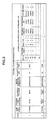
- Fig. 3 shows a detailed example of the control table Tm.
- the first storage subsystem 20 creates this table by acquiring necessary information from the second storage subsystem 40, and registers such table in the shared memory 25.
- the VDEV# of this control table is a virtual device of the first storage system for mapping the external device of the second storage system to the internal volume of the first storage system.
- Valid path bitmap corresponds to the setting status of the logical path from the first storage subsystem 20 to the logical volume (LDEV) of the second storage subsystem.
- the total number of bits of the valid path bitmap shows the number of paths that can be set as a logical path. With the system of Fig. 2 , since a total of 8 paths can be set as the logical path as described above, the total number of bits is 8.
- External-side path mode shows the control method of the path to the external volume (LDEV) of the second storage subsystem.
- LDEV external volume
- AP active path/passive path
- Setting path mode is the control method when the first storage subsystem issues an I/O to the external volume (LDEV) of the second storage subsystem, and there is a single path mode, a pulse path mode, or an APLB (Active Passive Load Balancing) mode.
- LDEV external volume
- APLB Active Passive Load Balancing
- a single path mode is a mode for the first storage subsystem 20 to issue an I/O to one of the logical paths among the 8 paths
- a multi-path mode is a mode for the first storage subsystem to issue an I/O while balancing the load in all logical paths
- an APLB is a mode for issuing an I/O to a plurality of active paths (PA1 and PA2) in round robin.
- the first storage subsystem detects that an active path/passive path is set to the logical path to the external volume of the second storage subsystem, and sets APLB in the control table.
- Device identifying information is information for identifying the memory device configuring the VDE ⁇ /#.
- the capacity is the total storage capacity of the VDEV, and the device type shows the type of device (disk or tape, etc.).
- Externally connected path information unit in the control table explains the definition contents of the logical path from the first storage subsystem to the external volume (LDEV), and the path# is an entry of the logical path.
- External port# is an entry of the external port corresponding to the logical path.
- WWN is the World Wide Name for identifying the external port.
- LUN is the logical unit mapped to the external port.
- External-side A/P is the setting in the second storage subsystem for distinguishing whether the logical path corresponds to an active path or a passive path.
- the setting A/P is the setting in the first storage subsystem. If the first storage subsystem adopts the foregoing APLB mode, the first storage subsystem decides active or passive in accordance with the setting of the external A/P.
- “Status” is the status of the logical path. "Normal” shows that the logical path is normal, and shows that the transfer of the I/O is normal. "Passive” shows that the I/O is not being transferred, but the logical path is of a normal status.
- LDEV external volume
- LDEV external volume
- These plurality of logical paths are, as shown in Fig. 3 , mutually distinguished based on the external port number, the target port WWN, and the logical unit number (LUN). These items are registered by the user making input via the management apparatus 23.
- the first storage subsystem 40 refers to the definition of the logical paths P1 and P2 of the control table shown in Fig. 3 , and simultaneously transfers the I/O to these logical paths.
- the I/O is simultaneously issued from the external port 21-1 to the physical path S1, and from the external port 21-2 to the physical path S2 as shown with the curve of reference numeral 100.
- the switch refers to the command and transfers the I/O along the route shown in Fig. 3 .
- the I/O from the external ports 21-1, 21-2 of the first storage subsystem output with the multi-path mode is transferred to the external volume (LDEV) by sequentially passing through the external port 21-1, the physical path S1, the physical path T1, the target port 41A, the logical unit (LUN1), and the active path PA1.
- the I/O is transferred to the external volume (LDEV) by passing through the external port 21-2, the physical path S2, the physical path T2, the target port 41 B, the logical unit (LUN2), and the active path PA2.
- Fig. 4 is a flowchart showing the relevant parts of the processing for creating the control table of Fig. 3 during the process of mapping the memory device of the external storage subsystem 40 to the virtual volume of the first storage subsystem 20.
- the processing of S400 is explained in detail according to the time chart 406.
- the first storage subsystem acquires various types of information from the second storage subsystem.
- the first storage subsystem 20 logs into the second storage subsystem 40 from the external port (21A) of the channel adapter 21 via the switch circuit SW (S100).
- the login is complected when the second storage subsystem 40 returns a reply to the login of the first storage subsystem 20 (S102).
- the first storage subsystem 20 sends an inquiry command defined with a SCSI (Small Computer System Interface) standard is sent to the second storage subsystem (S104), and acquires detailed information (apparatus name, serial number, (LDEV)#, "Active”/"Passive” information) of the second storage subsystem 40 (S106).
- SCSI Small Computer System Interface
- the first storage subsystem thereafter makes an inquiry to the second storage subsystem regarding the capacity of the memory device (S108), and the second storage subsystem replies to this inquiry (S110),
- the CHA 21 of the first storage subsystem maps the storage area of the memory device of the second storage subsystem to its own volume based on the acquired information, registers specific information in the control table Tm of Fig. 3 during that process, and registers this control table in the shared memory 25.
- the inquiry command is used for clarifying the type and configuration of the apparatus of the inquiree, and it is thereby possible to comprehend the physical structure by penetrating the hierarchy of the inquiree apparatus.
- a failover is the processing of transferring the control right of the active path to the passive path.
- Fig. 5 is a block diagram explaining the failover processing.
- the physical path S1 was subject to a failure and blocked.
- the CHA of the first storage subsystem 20 When the CHA of the first storage subsystem 20 detects the blockade of the physical path S1 based on the failure detection program, it registers a failure status of "Blockade" to the status of the logical path P relating to the physical path blocked from the control table Tm.
- the failover control program stored in the local memory of the CHA transfers the I/O to the passive logical paths P3 and P4.
- the controller of the CHA updates and registers the status of the logical path P2 from “Normal” to "Passive,” and updates the status of the logical paths P3 and P4 from “Passive” to “Normal” based on the failover control program.
- "Blockade” is registered in the logical path P1.
- the CHA simultaneously sends the I/O to a group 102 configured from the physical paths S3 and S4 in order to send the I/O to the logical paths P3, P4 delegated with the control right in round robin based on the I/O transfer control program.
- Fig. 6 is a block diagram explaining the failback processing for returning the system after failover to a status before failover.
- the failover control program When the failure detection program of the CHA detects that the failure of the physical path S1 has been corrected, the failover control program returns the control table Tm from the status shown in Fig. 5 to the status before the failure occurred (Tm of Fig. 6 ).
- the status of the logical path P2 is updated from “Passive” to “Normal”
- the status of the logical paths P3 and P4 is updated from “Normal” to “Passive”
- the status of the logical path P1 is changed from "Blockade” to "Normal.”
- the I/O transfer control program refers to the control table updated to the foregoing status, determines that the I/O control right has been returned from the logical paths P3, P4 to the logical paths P1 and P2, and the I/O transfer from the first storage subsystem to the second storage subsystem is thereby resumed via the physical paths P1 and P2.
- the reason for performing the failback processing is to maintain the transfer order in the I/O transfer to the external volume via the active logical path.
- Fig. 7 is a flowchart for controlling the failover and failback processing described above. This flowchart is executed by the first storage subsystem CHA based on the failover control program.
- the CHA controller of the first storage subsystem determines whether it is necessary to perform failover or failback processing, and updates the logical path status of the control table.
- the controller under the control of the failure detection program, updates the path status of the logical path affected by the occurrence of a failure or recovery from a failure among the logical path groups identified with the parameters (VDEV#, path#) of Fig. 3 (S700).
- the controller refers to the control table Tm and acquires the total number (total number of "Active” configured normal paths) of normal paths (paths not registered as “Blockade") in which the path status is set to "Normal” or "Passive” regarding the logical paths set as active paths among the logical path groups, and the total number (total number of "Passive” configured normal paths) of normal paths in which the path status is set to "Normal” or “Passive” regarding the logical paths set as passive paths among the logical path groups (S702).
- the controller determines whether the total number of "Active" configured normal paths is smaller than a given value (S704). If this given Value is "1," as shown in Fig. 5 , the controller is able to detect that a failure has occurred in the physical path S1.
- controller obtains a positive result in the determination at S704, it compares the total number of "Active” configured normal paths and the total number of "Passive” configured normal paths (S706),
- the controller determines that the I/O transfer in the APLB mode can be controlled even upon transferring the I/O control right to the passive path and proceeds to S708, and, as shown in the control table Tm of Fig. 5 , updates the status of the "Active” configured normal path from “Normal” to "Passive” and updates the status of the "Passive” configured normal path from "Passive” to "Normal.”
- the controller obtains a negative result in the determination at S704, it determines that the update of the path status at S700 is the recovery from a failure and updates the status of the "Active” configured normal path from "Passive” to “Normal” and updates the status of the "Passive” configured normal path from "Normal” to “Passive” (S710).
- the controller obtains a negative result in the determination at S706, it determines that the failover processing cannot be performed since the number of passive paths is insufficient when a failure occurs in the active path, and ends the processing without performing the failover processing.
- the flow from S700 to S708 corresponds to a failover and the flow from S700 to S710 corresponds to a failback.
- the path status of the control table is updated at S700, S706, and S708, respectively.
- the first storage subsystem issuing an I/O using a single path mode using one logical path instead of transferring the I/O to the plurality of logical paths with the APLB mode. For example, this would be a case where the I/O tendency from the host computer is a sequential access.
- the configured path mode of the first storage subsystem can be suitably set or changed based on the I/O pattern from the host system.
- the recommended path mode when the I/O pattern from the host system is a sequential access is the single path mode, and the recommended path mode in the case of a random access is the multi-path mode or the APLB mode.
- the user refers to the recommended mode and sets or changes the path mode of the first storage subsystem 20.
- Fig. 8 shows a flowchart for setting or changing the I/O transfer mode to the first storage system based on the user setting made via the management program of the SVP 23 as the management unit of the storage subsystem.
- the management program checks the mode requested by the user (S800). If the requested mode is a single mode, the management unit checks the configuration information of the shared memory 25, and, if the requested mode and the set mode are different, sends a path mode switch command to the first storage subsystem (S802).
- the first storage subsystem When the first storage subsystem receives this request (S804), it registers the single path mode as the requested path mode in the configured path mode of the control table ( Fig. 3 ) (S806). When this update is complete, the first storage subsystem notifies the management program to such effect, and the management program that received this notice ends the processing.
- the I/O transfer program of the first storage subsystem sends the I/O to one logical path among the plurality of logical paths. If a plurality of logical paths are set as active, the I/O is output to one logical path.
- the management program acquires information of the second storage subsystem from the control table recorded in the shared memory 25 (S812), it checks whether the second storage subsystem is supporting the multi-path mode (S814).
- the management program notifies the user that the path mode cannot be switched (S816). Meanwhile, if the multi-path mode is supported, the path mode is updated and stored as per the foregoing explanation.
- the path status of the control table in the case of the multi-path mode is set to "Normal" for all logical paths.
- the management program checks whether the second storage subsystem is supporting this mode, and, if this is denied, the management program notifies the processing to the user and ends the processing (S822). Meanwhile, if this is affirmed, the management program updates and stores the path mode as per the foregoing explanation.
- Fig. 9 is a flowchart for the I/O transfer program of the CHA of the first storage subsystem to detect the I/O pattern from the host system and set or change the path mode.
- the management program stored in the local memory of the CHA checks the I/O pattern from the host system (S900) and, if this is a random access, checks whether the configured path mode of the control table is a single path mode (S902).
- the configured path mode is either the multi-path mode or the APLB mode, and is a mode that is suitable for the I/O transfer of random access.
- the CHA ends the processing.
- the CHA 21 reads information of the second storage subsystem from the shared memory 25, and checks whether the second storage subsystem supports the multi-path mode (S904).
- the CHA determines control information indicating that the second storage subsystem is supporting this mode, the CHA changes the path mode of the control table from the single path mode to the multi-path mode (S906), and processing the random access from the host system in round robin that issues the I/O to a plurality of logical paths.
- the CHA checks whether the second storage subsystem is supporting the active path/passive path (S908). If this is affirmed, the CHA sets the path mode of the control table to APLB (S910), and if this is denied, the random access from the host system cannot be transferred to the plurality of logical paths, and therefore processes the host I/O in the single path mode of transferring the I/O to one logical path.
- the CHA determines whether the path mode set in the control table is the multi-path mode or the APLB mode (S912). If this is affirmed, the CHA changes the path mode to a single path mode.
- the CHA obtains a negative result in this determination, it ends the processing since it deems that the configured path mode is the single path mode that is suitable for sequential access.
- the optimal method of issuing the I/O to the logical path can be realized in the I/O transfer from the first storage subsystem to the external volume of the second storage subsystem. Moreover, based on the processing method shown in Fig. 9 , the method of issuing the I/O to the logical path can be dynamically set to the optimal pattern for the I/O pattern issued from the host system to the first storage subsystem.
- Fig. 10 shows a management screen for setting the path between the first storage system 20 and the second storage subsystem 40, and this is provided from the management terminal 23 to the user.
- This path is defined based on the identification number (CL1-A, CL5-A) of the external port and the WWN of the target port.
- the management screen shows the external volume, the gist thereof, the path usage mode, and the volume status.
- Fig. 11 is a management screen showing further detailed information, and, in addition to the information of Fig. 10 , displays the logical unit number (LUN) of the second storage subsystem and the status of the path status table corresponding to the path between the storage subsystems.
- LUN logical unit number
Landscapes
- Engineering & Computer Science (AREA)
- Theoretical Computer Science (AREA)
- Physics & Mathematics (AREA)
- General Engineering & Computer Science (AREA)
- General Physics & Mathematics (AREA)
- Human Computer Interaction (AREA)
- Quality & Reliability (AREA)
- Computer Networks & Wireless Communication (AREA)
- Hardware Redundancy (AREA)
- Information Retrieval, Db Structures And Fs Structures Therefor (AREA)
- Memory System Of A Hierarchy Structure (AREA)
Applications Claiming Priority (1)
| Application Number | Priority Date | Filing Date | Title |
|---|---|---|---|
| JP2008093972A JP2009245379A (ja) | 2008-03-31 | 2008-03-31 | ストレージシステム及びストレージシステムの制御方法 |
Publications (2)
| Publication Number | Publication Date |
|---|---|
| EP2107449A2 true EP2107449A2 (de) | 2009-10-07 |
| EP2107449A3 EP2107449A3 (de) | 2010-09-01 |
Family
ID=40823291
Family Applications (1)
| Application Number | Title | Priority Date | Filing Date |
|---|---|---|---|
| EP08171195A Withdrawn EP2107449A3 (de) | 2008-03-31 | 2008-12-10 | Speichersystem und Steuerverfahren für ein Speichersystem |
Country Status (3)
| Country | Link |
|---|---|
| US (2) | US8086768B2 (de) |
| EP (1) | EP2107449A3 (de) |
| JP (1) | JP2009245379A (de) |
Cited By (1)
| Publication number | Priority date | Publication date | Assignee | Title |
|---|---|---|---|---|
| EP2677430A1 (de) * | 2012-05-28 | 2013-12-25 | Fujitsu Limited | Relaisvorrichtung, Verbindungsverwaltungsverfahren und Informationsübertragungssystem |
Families Citing this family (10)
| Publication number | Priority date | Publication date | Assignee | Title |
|---|---|---|---|---|
| JP2009245379A (ja) * | 2008-03-31 | 2009-10-22 | Hitachi Ltd | ストレージシステム及びストレージシステムの制御方法 |
| EP2418580B1 (de) * | 2010-08-10 | 2012-10-10 | Siemens Aktiengesellschaft | Verfahren zum Betreiben eines Netzwerkes und Netzwerk |
| WO2012019321A1 (en) | 2010-08-13 | 2012-02-16 | Telefonaktiebolaget L M Ericsson (Publ) | Automatic guard period adjustment in time division duplexed wireless communication |
| WO2012035618A1 (ja) * | 2010-09-14 | 2012-03-22 | 富士通株式会社 | ストレージシステム、ストレージシステムのアクセス制御方法及びコンピュータシステム |
| US8577934B2 (en) * | 2011-03-24 | 2013-11-05 | Spectra Logic Corporation | System and method for a storage system response with data migration |
| US9268493B2 (en) * | 2012-11-28 | 2016-02-23 | Dell Products L.P. | Systems and methods for smart storage interconnection in a heterogeneous storage environment |
| US9547459B1 (en) * | 2013-06-27 | 2017-01-17 | EMC IP Holding Company LLC | Techniques for data relocation based on access patterns |
| US11003357B2 (en) * | 2019-09-13 | 2021-05-11 | EMC IP Holding Company LLC | Managing single path communication between a host and a storage system |
| JP2021047786A (ja) * | 2019-09-20 | 2021-03-25 | 富士通株式会社 | ストレージ制御装置、ストレージ装置及び決定プログラム |
| US20240111455A1 (en) * | 2022-09-30 | 2024-04-04 | Western Digital Technologies, Inc. | Control Table Set Management In Storage Devices |
Citations (3)
| Publication number | Priority date | Publication date | Assignee | Title |
|---|---|---|---|---|
| JP2006178811A (ja) | 2004-12-24 | 2006-07-06 | Hitachi Ltd | ストレージシステム及びストレージシステムのパス制御方法 |
| JP2007265243A (ja) | 2006-03-29 | 2007-10-11 | Hitachi Ltd | 計算機システム及び論理パス切替方法 |
| JP2008093972A (ja) | 2006-10-12 | 2008-04-24 | Sumitomo Chemical Co Ltd | 樹脂多層板の製造方法 |
Family Cites Families (18)
| Publication number | Priority date | Publication date | Assignee | Title |
|---|---|---|---|---|
| US5408646A (en) * | 1991-03-29 | 1995-04-18 | International Business Machines Corp. | Multipath torus switching apparatus |
| FR2767242B1 (fr) * | 1997-08-07 | 1999-10-15 | Alsthom Cge Alcatel | Dispositif et procede de commutation de cellules atm a groupes de connexions, et fonctions terminales d'entree et de sortie correspondantes |
| US6112257A (en) * | 1997-09-24 | 2000-08-29 | Emc Corporation | Dynamic adjustment of mirror service policy for logical volumes in a disk drive system based on collected statistics |
| US6145028A (en) * | 1997-12-11 | 2000-11-07 | Ncr Corporation | Enhanced multi-pathing to an array of storage devices |
| US6868083B2 (en) * | 2001-02-16 | 2005-03-15 | Hewlett-Packard Development Company, L.P. | Method and system for packet communication employing path diversity |
| JP2005010956A (ja) * | 2003-06-17 | 2005-01-13 | Hitachi Ltd | 情報処理装置の制御方法、情報処理装置、情報処理システム、及びプログラム |
| JP4220860B2 (ja) * | 2003-08-22 | 2009-02-04 | 富士通株式会社 | ストレージ制御装置 |
| US7664032B2 (en) * | 2003-11-10 | 2010-02-16 | Oki Electric Industry Co., Ltd. | Communication terminal and communication network |
| JP4426275B2 (ja) * | 2003-12-16 | 2010-03-03 | 株式会社日立製作所 | リモートコピー制御方法 |
| JP4643198B2 (ja) * | 2004-07-28 | 2011-03-02 | 株式会社日立製作所 | 負荷分散コンピュータシステム、経路設定プログラム及びその方法 |
| JP4646574B2 (ja) * | 2004-08-30 | 2011-03-09 | 株式会社日立製作所 | データ処理システム |
| JP4123386B2 (ja) * | 2004-10-27 | 2008-07-23 | 日本電気株式会社 | 通信パス冗長化システム、通信パスの冗長化方法及び負荷分散プログラム |
| JP4609848B2 (ja) * | 2005-04-06 | 2011-01-12 | 株式会社日立製作所 | 負荷分散コンピュータシステム、経路設定プログラム及びその方法 |
| JP2007088949A (ja) | 2005-09-22 | 2007-04-05 | Fujitsu Ltd | 情報処理装置、通信負荷分散方法および通信負荷分散プログラム |
| JP2007148812A (ja) * | 2005-11-28 | 2007-06-14 | Hitachi Ltd | ストレージシステム及びその負荷分散方法 |
| JP2007328611A (ja) * | 2006-06-08 | 2007-12-20 | Hitachi Ltd | ストレージ仮想化システム及び方法 |
| US20080301333A1 (en) * | 2007-06-04 | 2008-12-04 | International Business Machines Corporation | System and article of manufacture for using host and storage controller port information to configure paths between a host and storage controller |
| JP2009245379A (ja) * | 2008-03-31 | 2009-10-22 | Hitachi Ltd | ストレージシステム及びストレージシステムの制御方法 |
-
2008
- 2008-03-31 JP JP2008093972A patent/JP2009245379A/ja active Pending
- 2008-06-09 US US12/155,718 patent/US8086768B2/en not_active Expired - Fee Related
- 2008-12-10 EP EP08171195A patent/EP2107449A3/de not_active Withdrawn
-
2011
- 2011-11-29 US US13/306,627 patent/US8578073B2/en not_active Expired - Fee Related
Patent Citations (3)
| Publication number | Priority date | Publication date | Assignee | Title |
|---|---|---|---|---|
| JP2006178811A (ja) | 2004-12-24 | 2006-07-06 | Hitachi Ltd | ストレージシステム及びストレージシステムのパス制御方法 |
| JP2007265243A (ja) | 2006-03-29 | 2007-10-11 | Hitachi Ltd | 計算機システム及び論理パス切替方法 |
| JP2008093972A (ja) | 2006-10-12 | 2008-04-24 | Sumitomo Chemical Co Ltd | 樹脂多層板の製造方法 |
Cited By (1)
| Publication number | Priority date | Publication date | Assignee | Title |
|---|---|---|---|---|
| EP2677430A1 (de) * | 2012-05-28 | 2013-12-25 | Fujitsu Limited | Relaisvorrichtung, Verbindungsverwaltungsverfahren und Informationsübertragungssystem |
Also Published As
| Publication number | Publication date |
|---|---|
| US20090248916A1 (en) | 2009-10-01 |
| EP2107449A3 (de) | 2010-09-01 |
| US8578073B2 (en) | 2013-11-05 |
| US8086768B2 (en) | 2011-12-27 |
| JP2009245379A (ja) | 2009-10-22 |
| US20120072623A1 (en) | 2012-03-22 |
Similar Documents
| Publication | Publication Date | Title |
|---|---|---|
| EP2107449A2 (de) | Speichersystem und Steuerverfahren für ein Speichersystem | |
| US6625747B1 (en) | Computer storage system and failover method | |
| US7603507B2 (en) | Storage system and method of storage system path control | |
| US8484425B2 (en) | Storage system and operation method of storage system including first and second virtualization devices | |
| US8819374B1 (en) | Techniques for performing data migration | |
| JP5489601B2 (ja) | 物理及び仮想マルチパス入出力を動的に管理する方法、装置、システム、及びプログラム | |
| EP1571542B1 (de) | Speichersteuerungssystem und -verfahren | |
| US8316161B1 (en) | Techniques for indicating a passive path state for a device | |
| US6816917B2 (en) | Storage system with LUN virtualization | |
| US8281033B1 (en) | Techniques for path selection | |
| US8601085B1 (en) | Techniques for preferred path determination | |
| US9026694B1 (en) | Techniques for workload redistibution | |
| US7406039B2 (en) | System and method for a failover protocol in storage area network controllers | |
| KR101425698B1 (ko) | 다중 경로화 제공 방법, 시스템 및 컴퓨터 판독 가능한 매체 | |
| EP1760591B1 (de) | System und Verfahren zur Zugriffspfadverwaltung | |
| EP1324182A2 (de) | System und Verfahren zur Bereitstellung einer Überlagerung mit virtueller Funktionalität für Peripheriegerät | |
| US8219760B2 (en) | Storage subsystem and its control method | |
| US8972656B1 (en) | Managing accesses to active-active mapped logical volumes | |
| US8972657B1 (en) | Managing active—active mapped logical volumes | |
| US8745326B2 (en) | Request priority seek manager | |
| WO2014061054A1 (en) | Storage system and method of controlling storage system | |
| US7975118B2 (en) | Storage system and data rearrangement method | |
| US8762671B2 (en) | Storage apparatus and its control method | |
| JP2009295045A (ja) | ストレージシステム、ストレージサブシステム、及び記憶制御方法 | |
| US7441009B2 (en) | Computer system and storage virtualizer |
Legal Events
| Date | Code | Title | Description |
|---|---|---|---|
| PUAI | Public reference made under article 153(3) epc to a published international application that has entered the european phase |
Free format text: ORIGINAL CODE: 0009012 |
|
| AK | Designated contracting states |
Kind code of ref document: A2 Designated state(s): AT BE BG CH CY CZ DE DK EE ES FI FR GB GR HR HU IE IS IT LI LT LU LV MC MT NL NO PL PT RO SE SI SK TR |
|
| AX | Request for extension of the european patent |
Extension state: AL BA MK RS |
|
| PUAL | Search report despatched |
Free format text: ORIGINAL CODE: 0009013 |
|
| AK | Designated contracting states |
Kind code of ref document: A3 Designated state(s): AT BE BG CH CY CZ DE DK EE ES FI FR GB GR HR HU IE IS IT LI LT LU LV MC MT NL NO PL PT RO SE SI SK TR |
|
| AX | Request for extension of the european patent |
Extension state: AL BA MK RS |
|
| 17P | Request for examination filed |
Effective date: 20110301 |
|
| AKX | Designation fees paid |
Designated state(s): AT BE BG CH CY CZ DE DK EE ES FI FR GB GR HR HU IE IS IT LI LT LU LV MC MT NL NO PL PT RO SE SI SK TR |
|
| STAA | Information on the status of an ep patent application or granted ep patent |
Free format text: STATUS: THE APPLICATION IS DEEMED TO BE WITHDRAWN |
|
| 18D | Application deemed to be withdrawn |
Effective date: 20160701 |