EP2107617A1 - Architektonische Abdeckung mit photovoltaischen Modulen - Google Patents
Architektonische Abdeckung mit photovoltaischen Modulen Download PDFInfo
- Publication number
- EP2107617A1 EP2107617A1 EP08425215A EP08425215A EP2107617A1 EP 2107617 A1 EP2107617 A1 EP 2107617A1 EP 08425215 A EP08425215 A EP 08425215A EP 08425215 A EP08425215 A EP 08425215A EP 2107617 A1 EP2107617 A1 EP 2107617A1
- Authority
- EP
- European Patent Office
- Prior art keywords
- covering according
- panels
- modules
- photovoltaic
- covering
- Prior art date
- Legal status (The legal status is an assumption and is not a legal conclusion. Google has not performed a legal analysis and makes no representation as to the accuracy of the status listed.)
- Withdrawn
Links
- 229910021417 amorphous silicon Inorganic materials 0.000 claims description 3
- 238000012545 processing Methods 0.000 claims description 2
- 238000010276 construction Methods 0.000 abstract description 2
- 238000009434 installation Methods 0.000 description 5
- 230000005855 radiation Effects 0.000 description 5
- 230000004224 protection Effects 0.000 description 4
- 230000008901 benefit Effects 0.000 description 3
- 238000010586 diagram Methods 0.000 description 2
- 238000012423 maintenance Methods 0.000 description 2
- 239000000463 material Substances 0.000 description 2
- 229920002620 polyvinyl fluoride Polymers 0.000 description 2
- 241000239290 Araneae Species 0.000 description 1
- 230000004913 activation Effects 0.000 description 1
- 238000004891 communication Methods 0.000 description 1
- 238000013461 design Methods 0.000 description 1
- 239000006185 dispersion Substances 0.000 description 1
- 230000000694 effects Effects 0.000 description 1
- 239000011521 glass Substances 0.000 description 1
- 238000007689 inspection Methods 0.000 description 1
- 239000011159 matrix material Substances 0.000 description 1
- 230000007246 mechanism Effects 0.000 description 1
- 238000012544 monitoring process Methods 0.000 description 1
- 239000004417 polycarbonate Substances 0.000 description 1
- 229920000515 polycarbonate Polymers 0.000 description 1
- 230000009466 transformation Effects 0.000 description 1
Images




Classifications
-
- E—FIXED CONSTRUCTIONS
- E04—BUILDING
- E04H—BUILDINGS OR LIKE STRUCTURES FOR PARTICULAR PURPOSES; SWIMMING OR SPLASH BATHS OR POOLS; MASTS; FENCING; TENTS OR CANOPIES, IN GENERAL
- E04H6/00—Buildings for parking cars, rolling-stock, aircraft, vessels or like vehicles, e.g. garages
- E04H6/02—Small garages, e.g. for one or two cars
- E04H6/025—Small garages, e.g. for one or two cars in the form of an overhead canopy, e.g. carports
-
- F—MECHANICAL ENGINEERING; LIGHTING; HEATING; WEAPONS; BLASTING
- F24—HEATING; RANGES; VENTILATING
- F24S—SOLAR HEAT COLLECTORS; SOLAR HEAT SYSTEMS
- F24S25/00—Arrangement of stationary mountings or supports for solar heat collector modules
- F24S25/10—Arrangement of stationary mountings or supports for solar heat collector modules extending in directions away from a supporting surface
- F24S25/12—Arrangement of stationary mountings or supports for solar heat collector modules extending in directions away from a supporting surface using posts in combination with upper profiles
-
- H—ELECTRICITY
- H02—GENERATION; CONVERSION OR DISTRIBUTION OF ELECTRIC POWER
- H02S—GENERATION OF ELECTRIC POWER BY CONVERSION OF INFRARED RADIATION, VISIBLE LIGHT OR ULTRAVIOLET LIGHT, e.g. USING PHOTOVOLTAIC [PV] MODULES
- H02S20/00—Supporting structures for PV modules
- H02S20/10—Supporting structures directly fixed to the ground
-
- H—ELECTRICITY
- H02—GENERATION; CONVERSION OR DISTRIBUTION OF ELECTRIC POWER
- H02S—GENERATION OF ELECTRIC POWER BY CONVERSION OF INFRARED RADIATION, VISIBLE LIGHT OR ULTRAVIOLET LIGHT, e.g. USING PHOTOVOLTAIC [PV] MODULES
- H02S20/00—Supporting structures for PV modules
- H02S20/20—Supporting structures directly fixed to an immovable object
- H02S20/22—Supporting structures directly fixed to an immovable object specially adapted for buildings
-
- Y—GENERAL TAGGING OF NEW TECHNOLOGICAL DEVELOPMENTS; GENERAL TAGGING OF CROSS-SECTIONAL TECHNOLOGIES SPANNING OVER SEVERAL SECTIONS OF THE IPC; TECHNICAL SUBJECTS COVERED BY FORMER USPC CROSS-REFERENCE ART COLLECTIONS [XRACs] AND DIGESTS
- Y02—TECHNOLOGIES OR APPLICATIONS FOR MITIGATION OR ADAPTATION AGAINST CLIMATE CHANGE
- Y02B—CLIMATE CHANGE MITIGATION TECHNOLOGIES RELATED TO BUILDINGS, e.g. HOUSING, HOUSE APPLIANCES OR RELATED END-USER APPLICATIONS
- Y02B10/00—Integration of renewable energy sources in buildings
- Y02B10/10—Photovoltaic [PV]
-
- Y—GENERAL TAGGING OF NEW TECHNOLOGICAL DEVELOPMENTS; GENERAL TAGGING OF CROSS-SECTIONAL TECHNOLOGIES SPANNING OVER SEVERAL SECTIONS OF THE IPC; TECHNICAL SUBJECTS COVERED BY FORMER USPC CROSS-REFERENCE ART COLLECTIONS [XRACs] AND DIGESTS
- Y02—TECHNOLOGIES OR APPLICATIONS FOR MITIGATION OR ADAPTATION AGAINST CLIMATE CHANGE
- Y02B—CLIMATE CHANGE MITIGATION TECHNOLOGIES RELATED TO BUILDINGS, e.g. HOUSING, HOUSE APPLIANCES OR RELATED END-USER APPLICATIONS
- Y02B10/00—Integration of renewable energy sources in buildings
- Y02B10/20—Solar thermal
-
- Y—GENERAL TAGGING OF NEW TECHNOLOGICAL DEVELOPMENTS; GENERAL TAGGING OF CROSS-SECTIONAL TECHNOLOGIES SPANNING OVER SEVERAL SECTIONS OF THE IPC; TECHNICAL SUBJECTS COVERED BY FORMER USPC CROSS-REFERENCE ART COLLECTIONS [XRACs] AND DIGESTS
- Y02—TECHNOLOGIES OR APPLICATIONS FOR MITIGATION OR ADAPTATION AGAINST CLIMATE CHANGE
- Y02E—REDUCTION OF GREENHOUSE GAS [GHG] EMISSIONS, RELATED TO ENERGY GENERATION, TRANSMISSION OR DISTRIBUTION
- Y02E10/00—Energy generation through renewable energy sources
- Y02E10/40—Solar thermal energy, e.g. solar towers
- Y02E10/47—Mountings or tracking
-
- Y—GENERAL TAGGING OF NEW TECHNOLOGICAL DEVELOPMENTS; GENERAL TAGGING OF CROSS-SECTIONAL TECHNOLOGIES SPANNING OVER SEVERAL SECTIONS OF THE IPC; TECHNICAL SUBJECTS COVERED BY FORMER USPC CROSS-REFERENCE ART COLLECTIONS [XRACs] AND DIGESTS
- Y02—TECHNOLOGIES OR APPLICATIONS FOR MITIGATION OR ADAPTATION AGAINST CLIMATE CHANGE
- Y02E—REDUCTION OF GREENHOUSE GAS [GHG] EMISSIONS, RELATED TO ENERGY GENERATION, TRANSMISSION OR DISTRIBUTION
- Y02E10/00—Energy generation through renewable energy sources
- Y02E10/50—Photovoltaic [PV] energy
Definitions
- the present invention relates to an architectural covering for outdoor environments, fitted with photovoltaic panels.
- the present invention relates to structures such as cantilever roofs, gazeboes, sheds and the like, to be fitted with photovoltaic modules or panels.
- photovoltaic module will refer to a laminar component generally consisting of an upper transparent plate (made of polycarbonate, glass or the like) and a support plate made of a suitable material (e.g. PVC coated with Tedlar® or other weather-resistant materials), between which a set of cells (usually 36 or 72) is arranged.
- a laminar component generally consisting of an upper transparent plate (made of polycarbonate, glass or the like) and a support plate made of a suitable material (e.g. PVC coated with Tedlar® or other weather-resistant materials), between which a set of cells (usually 36 or 72) is arranged.
- two or more of these modules are assembled together in order to form a larger panel; to this end, in addition to being supported rigidly in the panel configuration, the modules are also connected electrically to one another in order to obtain the required voltage and/or current values.
- module will also refer to large laminar units (a few metres long) made up of thin layers of amorphous silicon, as will be described in detail later on.
- module thus appears to be less limiting, and therefore the following description and claims shall also apply to panels consisting of two or more assembled modules because the meaning of this term is compatible with the context.
- the orientation of the panels is not always optimal if we consider the solar radiation variations in the different seasons of the year; furthermore, the electric energy produced is often limited to domestic use, because the systems are rather small and have not been conceived for alternative applications.
- the present invention aims at improving this state of the art: that is, it aims at providing an architectural covering for outdoor environments specially designed for photovoltaic modules and panels, so as to obtain higher energetic efficiency and to increase the number of possible applications of said modules and panels, as well as of the structure itself.
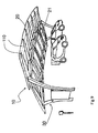
- reference numeral 1 designates as a whole a cantilever roof according to the present invention.
- Cantilever roof 1 comprises a plurality of photovoltaic panels 2, each consisting of three modules 2a, 2b, 2c, as shown in Figs. 5 and 6 , which are connected together structurally and electrically in a per se known manner.
- panels 2 make up the covering of the cantilever roof; in this example, they are mounted on a portal-type support structure, formed by two side abutment structures 4 and 5 joined by a pair of span camber beams 6, 7 extending on the upper part of the entire extent of the portal.
- Each side abutment structure 4 and 5 in turn comprises pairs of pillars 8, 9 and 10, 11 joined by a horizontal crossbeam 12, 13; as shown in the drawings, in this example both the pillars and the crossbeam are slightly curved, just like the camber beams 6, 7.
- photovoltaic panels 2 are mounted on the span beams 6, 7 in an adjustable manner, i.e. with the possibility of adjusting the inclination thereof according to solar radiation; for this purpose, panels 2 have, on the lower face, an H-shaped support structure 20 comprising a rest element 21 shaped as the tubular profile of the camber beams 6, 7, to which it is secured through a bracket 22 fastened with screws (not shown in the drawings).
- any other adjustable panel fastening system may be used as a substitute for the above-described one; this will depend on design choices related to costs, shape of the beams 6, 7, and the like.
- bracket 22 and rest 21 may be replaced with gyroscopic joints (i.e. spider joints) associated with nut-screw mechanisms allowing the panel orientation to be adjusted; furthermore in more costly applications, motorized adjustment systems powered by the energy supplied by the photovoltaic panels may also be used.
- gyroscopic joints i.e. spider joints
- motorized adjustment systems powered by the energy supplied by the photovoltaic panels may also be used.
- the panels are all of the same size, and the matrix arrangement thereof is regular as well, i.e. the panels are spaced evenly at a preset distance, so as to make up a covering that lets through a certain quantity of light, and also allowing air to pass along the space between the panels.
- each panel 2 is made up of three glass-tedlar modules 2a, 2b, 2c, each comprising seventy-two 125x125mm polycrystalline EWT cells, delivering a peak power of 170 W at a voltage of 42.9 V; each module has preferred dimensions of 810 mm x 1620 mm, with a thickness of 50 mm.
- Cantilever roof 1 comprises a control unit 30, housed in a cabinet 31 of the type generally used in outdoor environments for containing electric equipment, telephonic equipment or the like.
- the control unit receives electric energy from panels 2, to which it is connected by means of known cables (not shown in the drawings), even though it may also be provided with batteries (not shown) arranged inside cabinet 31.
- the control unit is a PLC type electronic computer provided with per se known means (processor, interfaces, network cards, etc.) in order to control the supply of the electric current generated by photovoltaic panels 2 to a number of user devices available in the cantilever roof; in this case, said user devices are power sockets 35 and luminous panels 36.
- the electric energy supply is of the type wherein user utilities are identified via radio frequency (RFID); systems of this type are already available on the market, like the one manufactured by company TAG Italia.
- RFID radio frequency
- Electric current is supplied according to the diagram of Fig. 9 .
- power socket 35 is prearranged for being coupled to plug 37 fitted with a known passive TAG device 38 (e.g. an integrated circuit); information is stored within TAG device 38 which allows the system to accurately identify every single user who requires the service by connecting thereto.
- a passive TAG device 38 e.g. an integrated circuit
- An RFID reader 39 installed in power socket 35 is connected to a control unit 30 through a normal wired line 40 incorporated into the cantilever roof (not shown in the other drawings): when plug 37 is inserted into the power socket 35, reader 39 identifies the user through the code stored in tag 38 and, when authorized, it activates control unit 30, which can manage the current supply by calculating the delivered quantity, in view of charging the user for the service provided.
- line 40 is connected (through a LAN, WAN or other network) to a remote operating unit 41 which manages the power supply service.
- cantilever roof 1 also comprises per se known means 43 (such as converters, rectifiers, transformers, etc.) for processing the electric current generated by panels 2 in order to obtain the intensity (Ampere) and voltage (Volt) values required for its delivery through power sockets 35.
- per se known means 43 such as converters, rectifiers, transformers, etc.
- said means, controlled by unit 30, may also adjust current voltage and intensity parameters by taking into account the variability of the electric energy produced by the photovoltaic panels, which is due to the different solar radiation occurring in the course of the day.
- the energy produced by the panels also supplies luminous panels 36, though for simplicity's sake the latter are not shown in Fig. 9 .
- cantilever roof 1 fully achieves the objects of the invention.
- cantilever roof 1 has no actual roof, shed or similar covering elements supporting panels 2, since the panels themselves provide the covering function; it follows that all the load-bearing structure consisting of abutment structures 4, 5 and span beams 6, 7 can be lighter, because it must not bear the weight of a roof over which the panels are laid, resulting in evident cost advantages.
- a light load-bearing structure can be installed in a relatively simple manner and be oriented at best with respect to the sun; it also simplifies the installation and maintenance of the photovoltaic systems, in that the covering is arranged near the ground and can be easily accessed for installation, inspection and maintenance, resulting in much lower costs compared to installations carried out on building roofs.
- control and protection boards, transformation inverters and any communication systems are all placed within watertight cabinet 31 located at the base of the structure, thus cutting down installation costs and avoiding any dispersion on the direct current (DC) side of the system, in addition to allowing the electric system to be monitored and maintained very easily.
- DC direct current
- the curved shape of beams 6, 7 contributes to providing optimal exposure of panels 2 to solar radiation, since it allows to attain a better orientation of the panels along the trajectory of the solar disc without them mutually shadowing one another.
- the particular configuration of the load-bearing structure and the possibility of adjusting the orientation of the panels allow to compensate for the lower solar radiation in northern areas; for example, think of the differences which are found in Italy between Alpine areas and southern regions.
- the covering according to the invention can be manufactured industrially on a large scale, since it is a product which is suitable for many applications.
- control unit 30 considerably increases the application possibilities of the cantilever roof; in fact, in addition to being used as a cover for people or objects, it also becomes a recharge station for electric vehicles (the socalled ZEVs or Zero Emission Vehicles), as shown in the drawings.
- ZEVs Zero Emission Vehicles
- the covering according to the invention allows to profitably use existing vehicle parking areas while providing an effective and useful shelter.
- the covering may also be fitted with audio and video systems (screens for displaying images, etc., in addition to luminous panels 36) networked with public services such as traffic information, weather forecasts, social announcements or other information services.
- audio and video systems screens for displaying images, etc., in addition to luminous panels 36
- public services such as traffic information, weather forecasts, social announcements or other information services.
- cantilever roof 1 is substantially independent from external electric networks.
- cantilever roof 1 is powering lighting micro-networks or technologic systems (air quality monitoring units, video surveillance systems, radio links, GSM-UMTS networks or wireless repeaters).
- lighting micro-networks or technologic systems air quality monitoring units, video surveillance systems, radio links, GSM-UMTS networks or wireless repeaters.
- Fig. 10 the cantilever roof parts which are structurally or functionally equivalent to the ones described above are designated by the same reference numerals followed by an apostrophe.
- cantilever roof 1' has only two modules 2' consisting of respective Unisolar type photovoltaic sheets, manufactured by company ECD Ovonics, arranged on a support structure which is substantially similar to the one shown in Fig. 1 ; the modules are mounted on beams 6', 7' through supports 20' provided on the underside thereof.
- Photovoltaic sheets 2' are preferably made of amorphous silicon, and allow to obtain continuous coverings ensuring optimal weather protection, which are inclined by about 10° relative to a horizontal plane.
- said supports correspond to the arms of the "H" shape of the supports of the previous example, whereas beams 6, 7' correspond to the central segment of the "H".
- the functions of the cantilever roof are nonetheless the same as those described above, except that the orientation of photovoltaic panels 2' can be adjusted by turning supports 20' about beams 6', 7'.
- panels 2' are separated by a space that allows them both to be turned without interference and to offer less resistance to the wind, which can blow through the space between two panels.
- cantilever roof 1" is smaller than the previous ones and comprises four photovoltaic panels 2" arranged on a single camber beam 6"; the side abutment structures consist of respective curved beams 8" and 10" connected together by a section 45 that accommodates the electric power sockets 35".
- This cantilever roof therefore is differentiated from the other ones in that electric power sockets 35" are not arranged on small columns as in the previous cases, but on section 45, which is also used as a structure stiffening element.
- Photovoltaic panels 2" are similar to those of Figs. 5, 6 , and are mounted in the same manner, with the H-shaped support 20" secured to the camber beam (not shown in Fig. 11 ); thus, cantilever roof 1" has a light multifunctional structure as well, in which panels 2", besides supplying electric energy, are also used as a covering without having to be laid over roofs or other existing surfaces.
- the photovoltaic-panel covering structure according to the invention can be implemented in multiple configurations.
Landscapes
- Engineering & Computer Science (AREA)
- Architecture (AREA)
- Structural Engineering (AREA)
- Civil Engineering (AREA)
- Chemical & Material Sciences (AREA)
- Thermal Sciences (AREA)
- Physics & Mathematics (AREA)
- Combustion & Propulsion (AREA)
- Mechanical Engineering (AREA)
- General Engineering & Computer Science (AREA)
- Sustainable Energy (AREA)
- Sustainable Development (AREA)
- Life Sciences & Earth Sciences (AREA)
- Roof Covering Using Slabs Or Stiff Sheets (AREA)
- Photovoltaic Devices (AREA)
Priority Applications (1)
| Application Number | Priority Date | Filing Date | Title |
|---|---|---|---|
| EP08425215A EP2107617A1 (de) | 2008-04-03 | 2008-04-03 | Architektonische Abdeckung mit photovoltaischen Modulen |
Applications Claiming Priority (1)
| Application Number | Priority Date | Filing Date | Title |
|---|---|---|---|
| EP08425215A EP2107617A1 (de) | 2008-04-03 | 2008-04-03 | Architektonische Abdeckung mit photovoltaischen Modulen |
Publications (1)
| Publication Number | Publication Date |
|---|---|
| EP2107617A1 true EP2107617A1 (de) | 2009-10-07 |
Family
ID=39943006
Family Applications (1)
| Application Number | Title | Priority Date | Filing Date |
|---|---|---|---|
| EP08425215A Withdrawn EP2107617A1 (de) | 2008-04-03 | 2008-04-03 | Architektonische Abdeckung mit photovoltaischen Modulen |
Country Status (1)
| Country | Link |
|---|---|
| EP (1) | EP2107617A1 (de) |
Cited By (13)
| Publication number | Priority date | Publication date | Assignee | Title |
|---|---|---|---|---|
| WO2011140557A1 (en) * | 2010-05-07 | 2011-11-10 | Arizona Board Of Regents, A Body Corporate Of The State Of Arizona, Acting For And On Behalf Of Arizona State University | A flexible system for car shading |
| FR2965041A1 (fr) * | 2010-09-21 | 2012-03-23 | Gagnepark | Systeme modulaire formant champ solaire et couverture d’une zone a couvrir |
| DE202012101518U1 (de) | 2012-04-24 | 2012-07-12 | Elektro Petring Gmbh | Solarcarport mit einer integrierten Ladestation |
| ITRM20110334A1 (it) * | 2011-06-24 | 2012-12-25 | Sapa Profili S R L | Pensilina fotovoltaica. |
| FR3014925A1 (fr) * | 2013-12-12 | 2015-06-19 | Mdsys Group | Abri pour voiture a energie solaire |
| EP2727153A4 (de) * | 2011-07-01 | 2015-06-24 | Lynn A Miller | Tragbares solar- und windbetriebenes energieerzeugungssystem |
| EP2616748A4 (de) * | 2010-08-26 | 2015-10-07 | Altumaxis Inc | Einstellbarer sonnenenergiekollektorhalter für eine überdachte parkhausstruktur und parkplatz damit |
| EP3041706A4 (de) * | 2013-10-02 | 2017-08-23 | Lt350, Llc | Solarüberdachung mit integriertem fach für hochleistungsbatterien |
| US10069456B2 (en) | 2013-10-02 | 2018-09-04 | Lt 350, Llc | Methods for loading battery storage compartments into a solar canopy support structure |
| CN109958308A (zh) * | 2017-12-26 | 2019-07-02 | 李金龙 | 一种分布式光伏发电智能停车充电停车位 |
| US11245138B2 (en) | 2013-10-02 | 2022-02-08 | Lt350, Llc | Energy storage canopy |
| US11916205B2 (en) | 2013-10-02 | 2024-02-27 | Lt 350, Llc | Energy storage canopy |
| DE102022129984A1 (de) | 2022-11-14 | 2024-05-16 | Audi Aktiengesellschaft | Carport ausrüstbar mit Funktionsmodulen, wie z.B. Photovoltaikmodulen, und System aus Carport und Funktionsmodulen |
Citations (4)
| Publication number | Priority date | Publication date | Assignee | Title |
|---|---|---|---|---|
| WO2005080124A2 (en) * | 2004-02-14 | 2005-09-01 | Brian Ellis | A pontoon |
| EP1626140A2 (de) * | 2004-08-09 | 2006-02-15 | Extel S.r.l. | Unterstand für Kraftfahrzeuge |
| EP1696087A1 (de) * | 2005-01-21 | 2006-08-30 | Corus Bausysteme GmbH | Carport |
| US20060207192A1 (en) * | 2001-07-10 | 2006-09-21 | Steven Durham | Energy generating shelter system and method |
-
2008
- 2008-04-03 EP EP08425215A patent/EP2107617A1/de not_active Withdrawn
Patent Citations (4)
| Publication number | Priority date | Publication date | Assignee | Title |
|---|---|---|---|---|
| US20060207192A1 (en) * | 2001-07-10 | 2006-09-21 | Steven Durham | Energy generating shelter system and method |
| WO2005080124A2 (en) * | 2004-02-14 | 2005-09-01 | Brian Ellis | A pontoon |
| EP1626140A2 (de) * | 2004-08-09 | 2006-02-15 | Extel S.r.l. | Unterstand für Kraftfahrzeuge |
| EP1696087A1 (de) * | 2005-01-21 | 2006-08-30 | Corus Bausysteme GmbH | Carport |
Cited By (15)
| Publication number | Priority date | Publication date | Assignee | Title |
|---|---|---|---|---|
| WO2011140557A1 (en) * | 2010-05-07 | 2011-11-10 | Arizona Board Of Regents, A Body Corporate Of The State Of Arizona, Acting For And On Behalf Of Arizona State University | A flexible system for car shading |
| EP2616748A4 (de) * | 2010-08-26 | 2015-10-07 | Altumaxis Inc | Einstellbarer sonnenenergiekollektorhalter für eine überdachte parkhausstruktur und parkplatz damit |
| FR2965041A1 (fr) * | 2010-09-21 | 2012-03-23 | Gagnepark | Systeme modulaire formant champ solaire et couverture d’une zone a couvrir |
| ITRM20110334A1 (it) * | 2011-06-24 | 2012-12-25 | Sapa Profili S R L | Pensilina fotovoltaica. |
| EP2727153A4 (de) * | 2011-07-01 | 2015-06-24 | Lynn A Miller | Tragbares solar- und windbetriebenes energieerzeugungssystem |
| DE202012101518U1 (de) | 2012-04-24 | 2012-07-12 | Elektro Petring Gmbh | Solarcarport mit einer integrierten Ladestation |
| EP3041706A4 (de) * | 2013-10-02 | 2017-08-23 | Lt350, Llc | Solarüberdachung mit integriertem fach für hochleistungsbatterien |
| US10069456B2 (en) | 2013-10-02 | 2018-09-04 | Lt 350, Llc | Methods for loading battery storage compartments into a solar canopy support structure |
| US11245138B2 (en) | 2013-10-02 | 2022-02-08 | Lt350, Llc | Energy storage canopy |
| US11476796B2 (en) | 2013-10-02 | 2022-10-18 | Lt 350, Llc | Methods for loading battery storage compartments into a solar canopy support structure |
| US11916205B2 (en) | 2013-10-02 | 2024-02-27 | Lt 350, Llc | Energy storage canopy |
| US12095408B2 (en) | 2013-10-02 | 2024-09-17 | Lt350, Llc | Solar canopy having a battery storage compartment |
| FR3014925A1 (fr) * | 2013-12-12 | 2015-06-19 | Mdsys Group | Abri pour voiture a energie solaire |
| CN109958308A (zh) * | 2017-12-26 | 2019-07-02 | 李金龙 | 一种分布式光伏发电智能停车充电停车位 |
| DE102022129984A1 (de) | 2022-11-14 | 2024-05-16 | Audi Aktiengesellschaft | Carport ausrüstbar mit Funktionsmodulen, wie z.B. Photovoltaikmodulen, und System aus Carport und Funktionsmodulen |
Similar Documents
| Publication | Publication Date | Title |
|---|---|---|
| EP2107617A1 (de) | Architektonische Abdeckung mit photovoltaischen Modulen | |
| US9564852B2 (en) | Solar-powered systems with solar cell support | |
| US10533717B2 (en) | Solar energy systems | |
| US11515830B2 (en) | Solar energy shade structure | |
| US20070079861A1 (en) | Solar rail or railing system | |
| US7285719B2 (en) | Solar array support methods and systems | |
| US9163859B2 (en) | Adjustable solar panel system | |
| EP2292877A1 (de) | Erzeugung von Photovoltaiksolarenergie und Anbringung an einer Fahrzeugabdeckung | |
| EP1313151A2 (de) | Vorrichtung zur Umwandlung des Sonnenlichts in elektrischen Strom | |
| US20120031488A1 (en) | Photovoltaic cell module assembly | |
| US20040065025A1 (en) | Energy generating shelter system and method | |
| EP1626140A2 (de) | Unterstand für Kraftfahrzeuge | |
| US20150113987A1 (en) | Integrated renewable energy and asset system | |
| US20120233939A1 (en) | Adjustable solar panel cap | |
| EP2326885A1 (de) | Sonnenenergieerzeugungsanordnung und verfahren zu deren bereitstellung | |
| US20140090310A1 (en) | Solar Roof Module for metal buildings | |
| CN117136495A (zh) | 模块化光伏电线杆系统 | |
| WO2014009541A2 (en) | Solar panel array | |
| US20140224325A1 (en) | Self-Contained Solar Power Unit | |
| WO2011013063A2 (en) | Photovoltaic electric power generator | |
| GB2634357A (en) | A structural photovoltaic (PV) panel and reinforced frame element adapted for modular construction and enclosures and PV devices formed therefrom | |
| US9973143B1 (en) | Solar panel roof modules | |
| CA2901475A1 (en) | New outdoor solar lighting system |
Legal Events
| Date | Code | Title | Description |
|---|---|---|---|
| PUAI | Public reference made under article 153(3) epc to a published international application that has entered the european phase |
Free format text: ORIGINAL CODE: 0009012 |
|
| AK | Designated contracting states |
Kind code of ref document: A1 Designated state(s): AT BE BG CH CY CZ DE DK EE ES FI FR GB GR HR HU IE IS IT LI LT LU LV MC MT NL NO PL PT RO SE SI SK TR |
|
| AX | Request for extension of the european patent |
Extension state: AL BA MK RS |
|
| AKX | Designation fees paid | ||
| REG | Reference to a national code |
Ref country code: DE Ref legal event code: 8566 |
|
| STAA | Information on the status of an ep patent application or granted ep patent |
Free format text: STATUS: THE APPLICATION IS DEEMED TO BE WITHDRAWN |
|
| 18D | Application deemed to be withdrawn |
Effective date: 20100408 |