EP2107637B1 - Gruppenantennenanordung und zugehöriges Verfahren - Google Patents
Gruppenantennenanordung und zugehöriges Verfahren Download PDFInfo
- Publication number
- EP2107637B1 EP2107637B1 EP09156963A EP09156963A EP2107637B1 EP 2107637 B1 EP2107637 B1 EP 2107637B1 EP 09156963 A EP09156963 A EP 09156963A EP 09156963 A EP09156963 A EP 09156963A EP 2107637 B1 EP2107637 B1 EP 2107637B1
- Authority
- EP
- European Patent Office
- Prior art keywords
- transceivers
- antenna array
- antenna
- transceiver
- sidelobes
- Prior art date
- Legal status (The legal status is an assumption and is not a legal conclusion. Google has not performed a legal analysis and makes no representation as to the accuracy of the status listed.)
- Active
Links
Images



Classifications
-
- H—ELECTRICITY
- H01—ELECTRIC ELEMENTS
- H01Q—ANTENNAS, i.e. RADIO AERIALS
- H01Q3/00—Arrangements for changing or varying the orientation or the shape of the directional pattern of the waves radiated from an antenna or antenna system
- H01Q3/26—Arrangements for changing or varying the orientation or the shape of the directional pattern of the waves radiated from an antenna or antenna system varying the relative phase or relative amplitude of energisation between two or more active radiating elements; varying the distribution of energy across a radiating aperture
- H01Q3/2605—Array of radiating elements provided with a feedback control over the element weights, e.g. adaptive arrays
-
- H—ELECTRICITY
- H01—ELECTRIC ELEMENTS
- H01Q—ANTENNAS, i.e. RADIO AERIALS
- H01Q1/00—Details of, or arrangements associated with, antennas
- H01Q1/12—Supports; Mounting means
- H01Q1/22—Supports; Mounting means by structural association with other equipment or articles
- H01Q1/24—Supports; Mounting means by structural association with other equipment or articles with receiving set
- H01Q1/241—Supports; Mounting means by structural association with other equipment or articles with receiving set used in mobile communications, e.g. GSM
- H01Q1/246—Supports; Mounting means by structural association with other equipment or articles with receiving set used in mobile communications, e.g. GSM specially adapted for base stations
-
- H—ELECTRICITY
- H01—ELECTRIC ELEMENTS
- H01Q—ANTENNAS, i.e. RADIO AERIALS
- H01Q3/00—Arrangements for changing or varying the orientation or the shape of the directional pattern of the waves radiated from an antenna or antenna system
- H01Q3/26—Arrangements for changing or varying the orientation or the shape of the directional pattern of the waves radiated from an antenna or antenna system varying the relative phase or relative amplitude of energisation between two or more active radiating elements; varying the distribution of energy across a radiating aperture
- H01Q3/267—Phased-array testing or checking devices
Definitions
- the invention relates to an antenna array for the transmission of signals which actively compensates for coverage loss by up tilting the antenna pattern and actively suppresses the sidelobes.
- Passive micro or macro antennas for example antennas used in mobile radio communications, comprise an antenna network with power splitters, passive amplitude tapers (attenuators) and passive phase shifters to feed multiple ones of antenna elements which form the antenna array.
- Each one of the individual antenna elements has a radiation pattern which is superposed and results in an overall radiation pattern of the antenna array in the far field.
- the antenna array will be arranged in a vertical manner (one column) and each of the antenna elements in the antenna array will be uniformly excited.
- the resulting vertical radiation pattern has a main lobe with a 3 dB half-power beam width and several sidelobes which are symmetrically arranged on both sides of the main lobe.
- the several sidelobes are not an issue as long as the main lobe is pointing to the horizon and the goal of the antenna array is to maximise coverage.
- the antenna array can physically be "downtilted" so that the main lobe does not point at the horizon but towards the ground.
- the downtilting is done either by a mechanically driven or an electrical tilt mechanism.
- One disadvantage of the mechanical downtilting of the antenna array is that a first (upper) one of the sidelobes above the main lobe could point to the horizon and as a result cause unwanted interference with the adjacent ones of the cells.
- the fixed side lobe suppression of the antenna array needs to be designed in such a way that, for all of possible downtilt values, the worst case side lobe suppression is fulfilled. This is typically implemented by fixed amplitude tapering that results in a lower overall gain of the antenna array.
- a flexible downtilting can be achieved by beam forming.
- the beam forming is implemented by multiplying individual complex values to each one of the individual transmission signals per antenna element.
- the advantage of beam forming through active antenna arrays compared to passive antenna arrays is that the downtilt is easily adjustable by digital signal processing instead of mechanically or by the electrical motors.
- the physical phase shifting or digital beam forming affects the relationship between the main lobe and the sidelobes. This change in relationship can result in the transmission of unacceptable interference to adjacent ones of the cells in particular, if the beam pattern is tilted far down low. To avoid this one has to design the relation between effective radiated power in the main beam and the required sidelobe suppression independent on the tilt setting, i.e. it requires an inefficient worst case design.
- a further issue which is known to occur in active antenna arrays is the failure of individual ones of the transceivers.
- the failure of the transceivers will not only result in an overall power degradation of 1/M (M being the total number of active elements) but also in a distortion of the radiation patterns.
- the distortion of the radiation pattern primarily results in the increase of the strength of the sidelobes which can also cause unwanted interference in adjacent ones of the cells.
- a similar problem also occurs in horizontal or two-dimensional beam forming using multidimensional antenna arrays. If, for example, the beam forming is used in spatial-division multiple access (SDMA) techniques the goal of the antenna array is to point its power only to a particular point of interest and to produce low intracell interference outside of the main lobe.
- SDMA spatial-division multiple access
- the prior art solutions suppress certain ones of the sidelobes of the antenna arrays.
- This sidelobe suppression is implemented in passive antenna array structures, for example, by fixing the attenuation of the feeding signal of the antennas such that the antenna elements near the edge of the antenna array are attenuated whereas the centre elements may have larger amplitudes.
- This design could lead to an overall antenna gain loss of 0.3 dB.
- Another known solution is to use passive phase shifting which would result in 0.2 dB output power losses.
- a further known solution is to apply spatial filter functions, like Tschebyscheff, which are used to filter the beam whilst accepting a certain output power backoff for some of the antenna elements.
- the M individual transceivers need to be optimized at individual output power levels dependent on the position of the individual transceivers within the active antenna array. This significantly reduces the flexibility of use of the M individual transceivers.
- the manufacture of different sizes of the antenna arrays with different antenna gains and different numbers of the M individual transceivers would require individual design of the different individual transceivers which is not advantageous for mass production of the individual transceivers.
- having only individual ones of the transceivers with identical constant maximum output power and applying amplitude tapering to achieve state of the art side lobe suppression would result in output power losses in the range of 2.5dB.
- the phase shifts required for beam forming a beam towards a certain angle depend on the distance between the antenna elements, the wavelength of the transmission signal and the direction of departure of the signal.
- the individual phase shifts needed at the individual ones of the M antenna elements to form the beam can be calculated.
- the antenna array has to be calibrated during manufacture by measuring the beam pattern for different ones of the direction of departure and deriving a set of M phase shifts for each direction of departure.
- the sets of M phase shifts can be stored in a look-up table.
- phase controller which controls the phase shift which is imparted by each transceiver to its signal and thus forms a main beam and its associated sidelobes.
- a perturbation phase generator portion of the phase controller adds a perturbation phase shift to form a relatively wide null in the sidelobe structure.
- JP 2001326525 (Kanazawa , et.al., assigned to Comm Res Lab) discloses a concept for maintaining a good user interferer separation for space division multiple access systems even in the case of an error in the phase control system of the antenna array.
- United States Patent Application Publication No. US 2006/0192711 A1 in the name of Haskell discloses a phased array antenna system with variable electrical tilt.
- the phased array antenna system can be adjusted so that a vertical radiation pattern satisfies a number of criteria: a) high boresight gain; b) the first upper side lobe should be at a level low enough to avoid causing interferences to mobiles using another base station; and c) the first lower side lobe should be at a level sufficient for communications to be possible in the antenna's immediately vicinity.
- European Patent Application EP 1 158 824 A2 discloses a control technique for a communication system.
- a two-dimensional array is provided at the same location as a base station.
- the base station serves a macrocell and the two-dimensional array serves a microcell.
- the two-dimensional array performs three-dimensional beamforming to steer the microcell to a desired location, namely, a hot spot. Filter tap weights may be adjusted for the antenna element to steer the beam to any desired location in the macrocell.
- the invention as defined in claim 1 provides an antenna array for the transmission of signals with a digital radio interface for connecting the antenna array with a transmitter and/or receiver, and with a plurality of antenna elements connected to a plurality of digital transceivers including digital up- and down conversion.
- the plurality of digital transceivers receives transceiver signals for transmission to the plurality of antenna elements.
- the antenna array also has a signal processor connected to the plurality of transceivers and which is adapted to weight, using complex values, the transceiver signals for automatically compensating for a coverage loss that goes along with power losses by tilt adjustments and for interference by adjusting sidelobes of the signals. This adjustment of the sidelobes allows interference from sidelobes to be reduced.
- the antenna array allows the generation of an antenna pattern with is optimized for each tilt value in terms of the relationship between effective radiated power and required sidelobe suppression.
- the antenna array has a failure detector or monitoring system connected to the plurality of digital transceivers.
- the failure detector or monitoring system autonomously detects malfunction of the individual transceivers and reports this to the signal processor without involvement of the transmitter and receiver.
- the antenna array has in one aspect of the invention a look-up table with the complex values used for weighting the transceiver signals.
- the complex values are in one aspect of the invention obtained from measurements.
- the failure detector detects failures of one or more of the plurality of transceivers.
- the signal processor can weight the transceiver signals to adjust the sidelobes of the signals and compensate for the coverage loss due to the failure by automatically lifting the downtilt angle of the antenna by a predefined angle depending on the original tilt angle without failure.
- the failure detector may comprise a feedback loop from at least one of the transceivers.
- the feedback loop may be used to convey a measured signal and/or data relative to the operation of the transceiver to the failure detector or monitoring and control system.
- the failure detector or monitoring and control system may analyze the feedback signal and/or the transceiver operation data and decide how to modify the complex values of individual transceivers.
- the failure detector or monitoring and control system may further or alternatively comprise a data polling unit.
- the data polling unit may collect state data from at least one of the transceivers.
- the state data could be for example a measured signal strength at the transceiver or the temperature of the transceiver.
- the invention as defined in claim 8 also provides a method for adjusting the sidelobes and the downtilt angle of the signals transmitted from the plurality of antenna elements.
- the method comprises detecting the requirement to adjust the sidelobes and downtilt angle.
- the detection of the requirement to adjust the sidelobes comprises a detection of a malfunction of at least one component of an antenna array.
- the method further comprises adjusting the weights of transceiver signals feeding the antenna elements such that the sidelobes are adjusted and a coverage loss that goes along with power losses is compensated by tilt adjustments.
- the method comprises detecting which at least one component of the antenna array is malfunctioning (or failing) and selecting the weights of the transceiver signals, such as to adjust the sidelobes and thereby compensate the malfunctioning of the at least one transceiver.
- the invention also provides a mechanism to reintegrate failed transceivers and to reset the weighting of the signals to its original values when the transceiver is functional again.
- One aspect of the invention relates to the usage of digital transceivers comprising at least one of digital up- and down converters for up/down converting the signals digitally from baseband to RF and vice versa.
- the digital up conversion transforms a low speed digital signal into a high speed digital signal. Due to the fact the RF signal is still digital, any micro phase and time alignments of the signals of the individual transceivers which are required to form a proper beam can be realized with low complexity.
- Figs. 1a and 1b show an overview of an active antenna array.
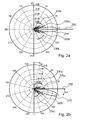
- Figs. 2a and 2b show an antenna array pattern without and with tilting, respectively, and without transceiver failure.
- Fig. 3 shows an antenna array pattern with tilting but without transceiver failure.
- Fig. 4 shows an antenna array pattern with tilting and with transceiver failure.
- Fig. 5 shows a flow chart for the method of operation of the invention.
- Figs. 1a, 1b show an overview of an active antenna array 10 according to an aspect of the invention.
- the active antenna array has a plurality of antenna elements 30 for transmission and reception of signals 20.
- Each of the antenna elements 30 is connected to a transceiver 40-1 - 40-8 (collectively 40).
- a transceiver 40-1 - 40-8 collectively 40.
- eight antenna elements 30 and eight transceivers 40 are shown. This is, however, only illustrative and the invention is not limited to this number of transceivers 40 and/or antenna elements 30.
- the transceivers 40 are connected to a signal processor 50 by means of a cable 47.
- the cable 47 in this aspect of the invention comprises eight individual cables leading from the signal processor 50 to separate ones of the transceivers 40.
- the transceivers 40 may be digital transceivers 40 whereas the signals transmitted via the cable 47 are digital signals.
- the signal processor 50 produces eight individual transceiver signals 45 for each ones of the antenna elements 30 as will be described below.
- the signal processor 50 receives from a base station 70 the digital signals for transmission by the active antenna array 10. Furthermore, the signal processor receives signals from the antenna elements 30 for providing a weighted combination of the received signals to the base station 70.
- the signal processor 50 is further connected to a look-up table 60 which contains complex values which are to be multiplied with each of the transceiver signals as will be explained below.
- the signal processor is connected to a monitoring and control unit 80 that monitors the functionality of each individual transceiver 40-1 - 40-8 as will be described below. Two embodiments of the invention are illustrated in Fig 1a and 1b .
- the signal processor 50 receives the signal from the unit 70 and separates the signal into eight different signals for transmission to the transceivers 40.
- the signal processor 50 weights the individual ones of the transceiver signals using the complex values that define a transmit antenna pattern and which are looked up in the look-up table 60.
- the complex values in the look-up table 60 result in either the phase of the transceiver signals 45 and/or the amplitude of the transceiver signals 45 being altered.
- the signal processor 50 receives the signal from the antenna 30 and combines the eight different signals for transmission to the base station 70.
- the signal processor 50 weights the individual ones of the transceiver signals 45 using the complex values that define a receive antenna pattern and which are looked up in the look-up table 60.
- the complex values in the look-up table 60 result in either the phase of the transceiver signals and/or the amplitude of the transceiver signals being altered.
- the complex values in the look-up table 60 could be calculated for each possible direction of departure of the transmitted signal 20 and for each possible failure of one of the antenna elements. It is, of course, not possible to store complex values in the look-up table 60 for all possible combinations of the direction of departure and the number of antenna elements. A selection of complex values is therefore made which is usable in practice.
- the tilt of the transmission signal could be between 0° and 14° and in steps of 1°. Therefore, the complex values are stored for each of the normal operation of all of these values of the tilt. It is also reasonable to assume that not all of the antenna elements 30 will fail at any one time. It is reasonable, to assume, for example, that only a maximum number of two or four of the transceivers 40 will fail at any moment.
- Fig. 2a shows the active antenna array 10 which is not tilted and in which all of the transceivers 40 are functioning correctly.
- the lighter line shows the main lobe 210 of the transmission signal 20. It will be seen from the figure that the main lobe is at 0° tilt and that the sidelobes 220u and 2201 (as well as other sidelobes collectively noted as 230u and 230l) are symmetrically arranged about the main lobe 210.
- the transceiver signals 45 to the transceivers 40 can be weighted within the signal processor 50 and the upper sidelobe 220u suppressed (as will be seen by the darker line in Fig. 2a ).
- the lower sidelobe 2201 as well as the further lower sidelobes 2301 are tilting downwards and are now stronger than the upper sidelobe 220u (and other upper sidelobes 230u) directed upwards.
- This is advantageous as the lower sidelobes 2201 and 2301 tilting downwards point within the cell and cannot interfere with the transmitters in other cells.
- the upper sidelobes 220u and 230u tilted upwards risk interference with adjacent cells and therefore it is advantageous to reduce the size of the upper sidelobes 220u and 230u substantially.
- FIG. 3 A further example of sidelobe suppression but with tilting is shown in Fig. 3 . It will be noticed in this figure that the main lobe 210 is now pointing at approximately 14° downwards. It will be further noted that the upper sidelobes 220u and 230u which are without suppression will be a little above the zero tilt (i.e. pointing to the horizon). As a result the first upper sidelobe 220u risks interfering with the adjacent cell. On applying the complex values from the look-up table 60 to the transceiver signals 45 it is possible to suppress the upper sidelobe 220u and increase the strength of the lower sidelobe 2201. This is shown by the lighter line in Fig. 3 .
- Fig. 4 now shows an example in which the direction of departure is tilted at 14°.
- a failure (or other malfunctioning) of one of the transceivers is assumed under several conditions. These conditions include the connection between central processing unit and an individual transceiver being down or no longer existent, the current and voltages of the power supply units of the transceivers being out of their normal ranges, the temperature sensors at the transceivers detectdetecting an increased temperature, or unacceptable deviations from the required output power are detected. It is also conceivable that one of the transceivers needs to be switched off for another reason. The transceiver can recover in case the cause that forced the system to shut down the transceiver is removed.
- a central controller unit 80 supervises the determination as to whether a defined "failure" occurs, if predefined conditions are met.
- the first upper sidelobe 220u is substantially increased in amplitude as is shown by the line in Fig. 4 .
- new complex values are fetched from the look-up table 60 and are used to weight these transceiver signals in the signal processor 50. This results in an amended weight adjusted antenna array pattern as is shown by the further line in Fig. 4 . It will be noted, that the amplitude of the main lobe 210 is reduced (as would be expected because two of the transceivers 40 are not working).
- the amended complex values lead to a substantial reduction in the amplitude of the first upper sidelobe 220u, but to an increase in the amplitude of the second upper sidelobe 230u. Again the increase in the amplitude of the second upper sidelobe 230u is not an issue because this second upper sidelobe 230u is tilted at approximately 25° and as a result does not interfere with the adjacent cell. Due to the failure of the transceivers 40-4 and 40-5 in the middle of the antenna array 10 the gain of the main lobe 210 is reduced by 2.84 dB due to the lower overall output.
- the monitoring and control unit 80 can notice the signal processor to use an antenna pattern with for the given failure scenario pre-defined lifted tilt value. Lifting the tilt angle can compensate for the coverage loss that goes along with the loss of the output power or the sensitivity that occurs when at least one transceiver of the antenna array is non-operational.
- Fig. 5 shows a flow chart for the method according to the invention.
- the calibration step 510 involves adding the complex values to the look-up table 60 which are required for the particular location of the antenna array.
- the complex values are determined dependent on simulations of the pattern of the antenna array 10 and the heuristic approach to find the side lobe optimum dependent of the failure scenario, the wanted direction of departure and the restriction on how many phases shall be corrected.
- the complex values can also be determined by measuring the antenna pattern and correcting manually the phases until an optimum side lobe suppression is achieved.
- the complex values will correspond to the sidelobe suppression and the degree of tilt required at the location in which the antenna array 10 is situated.
- the pattern correction is not only valid for the transmission of signals but also for reception of the signals.
- step 520 the transmission signals 20 are transmitted from the active antenna array 10 and will, of course, be received by receivers in the cell and signals from transmitters in the cell are received by the array.
- step 550 the link states of each connection between the signal processor 50 and each transceiver 40-1 - 40-8 is monitored. Furthermore, this realization of the invention considers an initial transceiver health data collection (e.g. current and voltages, temperature, etc.) locally done by a health data collector at each transceiver 40-1 - 40-8 whereas the data is digitally provided to the monitoring and control unit 80 via cable 47. This is shown in step 560 of the corresponding flow chart of Fig. 5 . The monitoring and control unit 80 extracts the digital health data from the transceiver signals which are also transmitted via the cable 47.
- an initial transceiver health data collection e.g. current and voltages, temperature, etc.
- the monitoring and control unit 80 extracts the digital health data from the transceiver signals which are also transmitted via the cable 47.
- the monitoring and control unit 80 in step 580 gives information about non-operational transceivers to the signal processor 50 or triggers the signal processor 50 to switch off either the transmit or the receive functionality or both of individual transceivers 40-1 - 40-8 as in step 590.
- the monitoring and control unit 80 may also provide information about which of the transceivers shall be reintegrated again according to step 610. Based on the information which transceiver is not operational any more or which transceiver needs to be reintegrated the signal processor 50 can chose the appropriate weights for beam forming from the lookup table 60 independently for the transmit and the receive direction in step 600 and 620, respectively.
- FIG 1b Another realization of the invention is illustrated in Fig 1b and considers the monitoring and control unit to be connected to the signal processor 50 and to each transceiver via an analog connection in order to enable loop back tests of the receive and the transmit functionality of each transceiver using the loop from the monitoring and control unit 80 via the signal processor 50, the transceivers 40 and back to the control and monitoring unit 80 for transmit functionality tests and vice versa for receive functionality tests.
- This addition to the failure detection process is illustrated in step 570 in the flow chart in Fig. 5 by the dashed activity box.
- each non-operational transceiver remains to be included in the monitoring process.
- the monitoring and control unit 80 detects that a non-operational transceiver could become functional again, it autonomously decides to reintegrate the non-operational transceiver again to become active.
- the signal processor 50 chooses again the weights for beam forming from the look up table 60 which are valid for the fully functional antenna array without failure.
- implementations may also be embodied in software (e.g., computer readable code, program code, and/or instructions disposed in any form, such as source, object or machine language) disposed, for example, in a computer usable (e.g., readable) medium configured to store the software.
- software e.g., computer readable code, program code, and/or instructions disposed in any form, such as source, object or machine language
- a computer usable (e.g., readable) medium configured to store the software.
- the apparatus and method described herein may be embodied as a combination of hardware and software.
Landscapes
- Engineering & Computer Science (AREA)
- Computer Networks & Wireless Communication (AREA)
- Variable-Direction Aerials And Aerial Arrays (AREA)
- Radar, Positioning & Navigation (AREA)
- Remote Sensing (AREA)
- Physics & Mathematics (AREA)
- General Physics & Mathematics (AREA)
Claims (10)
- Antennenanordnung (10) zur Übertragung von Signalen (20) mit:- einer digitalen Funkschnittstelle zum Verbinden der Antennenanordnung (10) mit einem Sender und/oder Empfänger,- einer Mehrzahl von Antennenelementen (30), die mit einer Mehrzahl von digitalen Sende-Empfängern (40), welche eine digitale Aufwärts- und Abwärtsumwandlung beinhalten, verbunden sind, wobei die Mehrzahl von digitalen Sende-Empfängern (40) Sende-Empfänger-Signale zur Übertragung zu der Mehrzahl von Antennenelementen (30) empfangen, und- einem Signalprozessor (50), der mit der Mehrzahl von Sende-Empfängern (40) verbunden ist und dazu eingerichtet ist, die Sende-Empfänger-Signale zu gewichten,dadurch gekennzeichnet, dass die Antennenanordnung (10) ferner aufweist:- einen Fehlerdetektor oder ein Überwachungs- und Steuersystem (80), der bzw. das mit der Mehrzahl von Sende-Empfängern (40) verbunden ist und eine Fehlfunktion von individuellen Sende-Empfängern (40) autonom detektiert,wobei der Signalprozessor (50) auch mit dem Fehlerdetektor oder Überwachungs- und Steuersystem (80) verbunden ist und dazu eingerichtet ist, die Sende-Empfänger-Signale unter Verwendung von komplexen Werten zu gewichten, um automatisch mittels Verkippungsanpassungen einen Abdeckungsverlust, der mit einem Verlust an Ausgangsleistung oder Sensitivität einhergeht, und Interferenz mittels Anpassen von Antennen-Nebenkeulen (220) basierend auf Informationen vom Fehlerdetektor oder Überwachungs- und Steuersystem (80) zu kompensieren.
- Antennenanordnung (10) nach Anspruch 1, ferner mit einer Lookup-Tabelle (60), welche die komplexen Werte für die Sende-Empfänger-Signale enthält.
- Antennenanordnung (10) nach einem der vorhergehenden Ansprüche, ferner mit einem Mechanismus, um komplexe Gewichte für die Sende-Empfänger-Signale unabhängig in Sende- und Empfangsrichtung auszuwählen.
- Antennenanordnung (10) nach einem der vorhergehenden Ansprüche, ferner mit einem autonomen Wiedereingliederungsmechanismus von defekten Sende-Empfängern für den Fall, dass die von dem Fehlerdetektor oder Überwachungs- und Steuersystem (80) detektierte Fehlfunktion nicht mehr existiert.
- Antennenanordnung (10) nach einem der vorhergehenden Ansprüche, ferner mit digitalen Sende-Empfängern mit digitaler Aufwärts- und Abwärtsumwandlung, um die Sende-Empfänger-Kalibration zu vereinfachen.
- Antennenanordnung (10) nach einem der vorhergehenden Ansprüche, wobei der Fehlerdetektor oder das Überwachungs- und Steuersystem (80) eine Rückkopplungsschleife von mindestens einem der Sende-Empfänger (40) aufweist.
- Antennenanordnung (10) nach einem der vorhergehenden Ansprüche, wobei der Fehlerdetektor oder das Überwachungs- und Steuersystem (80) eine Datenabfrageeinheit aufweist, die Zustandsdaten von mindestens einem der Sende-Empfänger (40) sammelt.
- Verfahren zur Kompensation von Abdeckungsverlust und zur Unterdrückung von Antennen-Nebenkeulen (220) in einem Antennenarray (10) mit einer Mehrzahl von Antennenelementen (30) mit den Schritten:- Detektieren der Erfordernis, Nebenkeulen (220) anzupassen, wobei das Detektieren die Detektion einer Fehlfunktion individueller Sende-Empfänger (40) der Antennenanordnung aufweist, und- Anpassen von Gewichten der die Antennenelemente (30) speisenden Sende-Empfänger-Signale unter Verwendung von komplexen Werten, so dass die Nebenkeulen (220) angepasst werden und mittels Verkippungsanpassungen ein Abdeckungsverlust, der mit einem Verlust an Ausgangsleistung oder Sensitivität einhergeht, basierend auf Informationen kompensiert wird, die aus der Detektion einer Fehlfunktion individueller Sende-Empfänger (40) hergeleitet sind.
- Verfahren nach Anspruch 8, ferner mit den Schritten:- Detektieren, welche der mindestens einen Komponente des Antennenanordnung (10) fehlfunktionierend ist, und- Auswählen der Gewichte der Sende-Empfänger-Signale (45), um die Nebenkeulen (220) anzupassen und dadurch das Fehlfunktionieren der mindestens einen Komponente zu kompensieren.
- Verfahren nach Anspruch 8, wobei die Detektion der Erfordernis, die Nebenkeulen (220) anzupassen, ferner das Verkippen der Antennenanordnung (10) aufweist.
Applications Claiming Priority (2)
| Application Number | Priority Date | Filing Date | Title |
|---|---|---|---|
| US4088708P | 2008-03-31 | 2008-03-31 | |
| GB0805826A GB2458900A (en) | 2008-03-31 | 2008-03-31 | Method and apparatus for suppression of sidelobes in antenna arrays |
Publications (2)
| Publication Number | Publication Date |
|---|---|
| EP2107637A1 EP2107637A1 (de) | 2009-10-07 |
| EP2107637B1 true EP2107637B1 (de) | 2011-06-08 |
Family
ID=39387055
Family Applications (1)
| Application Number | Title | Priority Date | Filing Date |
|---|---|---|---|
| EP09156963A Active EP2107637B1 (de) | 2008-03-31 | 2009-03-31 | Gruppenantennenanordung und zugehöriges Verfahren |
Country Status (4)
| Country | Link |
|---|---|
| US (2) | US20090243931A1 (de) |
| EP (1) | EP2107637B1 (de) |
| AT (1) | ATE512482T1 (de) |
| GB (1) | GB2458900A (de) |
Families Citing this family (22)
| Publication number | Priority date | Publication date | Assignee | Title |
|---|---|---|---|---|
| US8049661B1 (en) * | 2007-11-15 | 2011-11-01 | Lockheed Martin Corporation | Antenna array with robust failed-element processor |
| DE102010026039A1 (de) * | 2010-07-03 | 2012-01-05 | Thales Defence Deutschland Gmbh | Einrichtung und Verfahren zur räumlich begrenzten Beobachtung und Beeinflussung des Einsatzes von Kommunikationsendgeräten |
| CN102142869B (zh) * | 2010-11-22 | 2014-04-30 | 华为技术有限公司 | 有源天线的失效补偿方法、装置及有源天线设备 |
| EP2727184B1 (de) * | 2011-06-30 | 2018-12-26 | CommScope Technologies LLC | Aktivantennen-subarray-strukturen |
| CN102723974B (zh) * | 2012-05-24 | 2015-01-28 | 深圳市网信联动技术有限公司 | 一种自动调整智能天线广播波束的方法和系统 |
| US9856859B2 (en) * | 2012-06-26 | 2018-01-02 | Vestas Wind Systems A/S | Wind turbine blade vibration detection and radar calibration |
| CN102798769B (zh) * | 2012-08-02 | 2014-10-29 | 西北工业大学 | 基于回波损耗补偿的窄带天线测试方法 |
| US9702928B2 (en) | 2014-01-15 | 2017-07-11 | The Boeing Company | Self-healing array system and method |
| US20150355313A1 (en) * | 2014-06-06 | 2015-12-10 | Toyota Motor Engineering & Manufacturing North America, Inc. | Hybrid Data Adaptive and Decision Adaptive Antenna Array for Automotive Radar |
| US10056990B2 (en) * | 2014-08-12 | 2018-08-21 | Denki Kogyo Company, Limited | Base station antenna apparatus for mobile communication system |
| CN105704845A (zh) * | 2014-11-28 | 2016-06-22 | 深圳桑菲消费通信有限公司 | 一种多元相控阵天线使用的方法及装置 |
| US11018425B1 (en) * | 2015-05-01 | 2021-05-25 | Rockwell Collins, Inc. | Active electronically scanned array with power amplifier drain bias tapering for optimal power added efficiency |
| CN107645066B (zh) * | 2017-08-03 | 2024-06-14 | 东莞市云通通讯科技有限公司 | 提高副瓣抑制的通信基站天线 |
| EP3521852B1 (de) * | 2018-01-31 | 2021-07-14 | Sivers Wireless AB | Radarstrahlformungsverfahren |
| CN108549058B (zh) * | 2018-02-28 | 2022-05-13 | 四川九洲电器集团有限责任公司 | 一种二次雷达宽带有源相控阵系统及其动态校准方法 |
| US10985819B1 (en) * | 2018-10-16 | 2021-04-20 | Anokiwave, Inc. | Element-level self-calculation of phased array vectors using interpolation |
| CN109802400A (zh) * | 2019-01-29 | 2019-05-24 | 宁波大家小家网络科技有限公司 | 一种低压无功补偿系统的数据分析和处理的方法及系统 |
| KR102505063B1 (ko) | 2019-05-29 | 2023-03-02 | 삼성전자주식회사 | 무선 통신 시스템에서 빔 패턴을 복구하기 위한 장치 및 방법 |
| EP4038690A4 (de) * | 2019-09-30 | 2022-09-28 | Telefonaktiebolaget LM Ericsson (publ.) | Verfahren und vorrichtung zur fehlerabschwächung in einer basisstation |
| CN114830550A (zh) * | 2019-11-07 | 2022-07-29 | 弗劳恩霍夫应用研究促进协会 | 天线辐射图案的干扰感知适配 |
| US20220378325A1 (en) * | 2021-05-25 | 2022-12-01 | Metawave Corporation | Distributed Radar System With Active Tags For Precise Geolocation |
| US20260012896A1 (en) * | 2022-09-30 | 2026-01-08 | Jio Platforms Limited | System and method for automatic topographic interference detection and mitigation based on network data |
Citations (1)
| Publication number | Priority date | Publication date | Assignee | Title |
|---|---|---|---|---|
| WO2004030147A1 (en) * | 2002-09-24 | 2004-04-08 | Nokia Corporation | Compensating for radiation pattern in radio system, and radio system |
Family Cites Families (20)
| Publication number | Priority date | Publication date | Assignee | Title |
|---|---|---|---|---|
| US4924232A (en) * | 1988-10-31 | 1990-05-08 | Hughes Aircraft Company | Method and system for reducing phase error in a phased array radar beam steering controller |
| US5017927A (en) * | 1990-02-20 | 1991-05-21 | General Electric Company | Monopulse phased array antenna with plural transmit-receive module phase shifters |
| FR2672436B1 (fr) * | 1991-01-31 | 1993-09-10 | Europ Agence Spatiale | Dispositif de controle electronique du diagramme de rayonnement d'une antenne a un ou plusieurs faisceaux de direction et/ou de largeur variable. |
| US5610792A (en) * | 1994-03-01 | 1997-03-11 | Deshazo; Thomas R. | Apparatus for controlling the reset of a bus connected transceiver |
| CA2191956A1 (en) * | 1994-06-03 | 1995-12-14 | Telefonaktiebolaget Lm Ericsson | Microstrip antenna array |
| US5515060A (en) * | 1995-05-11 | 1996-05-07 | Martin Marietta Corp. | Clutter suppression for thinned array with phase only nulling |
| SE516142C2 (sv) * | 1999-03-12 | 2001-11-26 | Ericsson Telefon Ab L M | Kompensation av felaktiga element i antenngrupper |
| JP3440298B2 (ja) * | 2000-05-16 | 2003-08-25 | 独立行政法人通信総合研究所 | アレーアンテナの指向性制御方法 |
| US6950678B1 (en) * | 2000-05-24 | 2005-09-27 | Lucent Technologies Inc. | Control technique for a communication system |
| IL139077A0 (en) * | 2000-10-16 | 2001-11-25 | Wireless Online Inc | Method and system for reducing cell interference |
| US6597916B2 (en) * | 2001-12-26 | 2003-07-22 | Siemens Information And Communication Networks, Inc. | Hybrid architecture for supporting location determination in a wireless network |
| GB0307558D0 (en) * | 2003-04-02 | 2003-05-07 | Qinetiq Ltd | Phased array antenna system with variable electrical tilt |
| GB0325987D0 (en) * | 2003-11-07 | 2003-12-10 | Qinetiq Ltd | Phased array antenna system with controllable electrical tilt |
| US7133683B1 (en) * | 2003-11-12 | 2006-11-07 | Cellco Partnership | Position location SMDPP message retry mechanism |
| US7415881B2 (en) * | 2004-08-19 | 2008-08-26 | Fife Corporation | Ultrasonic sensor system for web-guiding apparatus |
| US7280070B2 (en) * | 2004-11-30 | 2007-10-09 | Unnikrishna Sreedharan Pillai | Robust optimal shading scheme for adaptive beamforming with missing sensor elements |
| US7345629B2 (en) * | 2006-02-21 | 2008-03-18 | Northrop Grumman Corporation | Wideband active phased array antenna system |
| US7970585B2 (en) * | 2007-06-29 | 2011-06-28 | Hewlett-Packard Development Company, L.P. | Method and system for remote monitoring and control of wireless cell-sites |
| US7619487B2 (en) * | 2007-09-14 | 2009-11-17 | Infineon Technologies Ag | Polar modulation without analog filtering |
| US9113042B2 (en) * | 2009-08-28 | 2015-08-18 | Broadcom Corporation | Multi-wireless device channel communications |
-
2008
- 2008-03-31 GB GB0805826A patent/GB2458900A/en not_active Withdrawn
-
2009
- 2009-03-31 AT AT09156963T patent/ATE512482T1/de not_active IP Right Cessation
- 2009-03-31 US US12/415,195 patent/US20090243931A1/en not_active Abandoned
- 2009-03-31 EP EP09156963A patent/EP2107637B1/de active Active
-
2013
- 2013-07-02 US US13/934,025 patent/US9318804B2/en active Active
Patent Citations (1)
| Publication number | Priority date | Publication date | Assignee | Title |
|---|---|---|---|---|
| WO2004030147A1 (en) * | 2002-09-24 | 2004-04-08 | Nokia Corporation | Compensating for radiation pattern in radio system, and radio system |
Also Published As
| Publication number | Publication date |
|---|---|
| ATE512482T1 (de) | 2011-06-15 |
| US20090243931A1 (en) | 2009-10-01 |
| US20130293409A1 (en) | 2013-11-07 |
| GB0805826D0 (en) | 2008-04-30 |
| US9318804B2 (en) | 2016-04-19 |
| EP2107637A1 (de) | 2009-10-07 |
| GB2458900A (en) | 2009-10-07 |
Similar Documents
| Publication | Publication Date | Title |
|---|---|---|
| EP2107637B1 (de) | Gruppenantennenanordung und zugehöriges Verfahren | |
| US11811147B2 (en) | Method for calibrating phased array antenna and related apparatus | |
| US10797807B2 (en) | Methods for calibrating millimeter wave antenna arrays | |
| EP3440784B1 (de) | Verfahren und vorrichtung zur auf kanalkapazität basierenden antennen-untergruppenschaltung | |
| EP2283540B1 (de) | System und verfahren zur mastvibrationskompensation | |
| AU691295B2 (en) | Antenna array calibration | |
| EP1204161B1 (de) | Verfahren und anordnung zur kalibrierung einer intelligenten gruppenantenne | |
| EP2396854B1 (de) | Kommunikationssystem, netzwerkelement, und verfahren zur antennenarray-kalibrierung | |
| KR101240438B1 (ko) | 위상 어레이 안테나의 무선 주파수 경로들을 교정하는 방법 | |
| WO2005067166A1 (en) | Adjust equipment and method for array antenna transmitting link | |
| US7342912B1 (en) | Selection of user-specific transmission parameters for optimization of transmit performance in wireless communications using a common pilot channel | |
| JP2007502597A (ja) | 無線通信システム、および、該システムにおけるバックホールビーム形成の調整方法 | |
| US8913513B2 (en) | Methods, testing apparatuses and devices for removing cross coupling effects in antenna arrays | |
| EP1808932B1 (de) | Vorrichtung zur Steuerung der Richtcharakteristik | |
| EP1627516A2 (de) | Koordination der strahlbildung in drahtlosen kommunikationssystemen | |
| KR20060015607A (ko) | 무선 통신 시스템에서의 빔 형성의 조정 | |
| EP2662927B1 (de) | Aktive Antennensteuerung | |
| WO2005041443A1 (ja) | 無線通信装置 | |
| US11601179B1 (en) | Coordinated beamforming of nodes in a wireless mesh network | |
| EP3323208B1 (de) | Verfahren und vorrichtung für einen zugangspunkt in einem punkt-zu-mehrpunkt-drahtlosnetzwerk | |
| JP3813537B2 (ja) | Cdma移動通信基地局装置 | |
| WO2025113786A1 (en) | Transmission of data signals from subarrays of an antenna array | |
| HK1100794B (en) | Method and apparatus for multi-beam antenna system | |
| WO2004056012A1 (en) | Method at multiple antennas | |
| HK1100794A1 (en) | Method and apparatus for multi-beam antenna system |
Legal Events
| Date | Code | Title | Description |
|---|---|---|---|
| PUAI | Public reference made under article 153(3) epc to a published international application that has entered the european phase |
Free format text: ORIGINAL CODE: 0009012 |
|
| AK | Designated contracting states |
Kind code of ref document: A1 Designated state(s): AT BE BG CH CY CZ DE DK EE ES FI FR GB GR HR HU IE IS IT LI LT LU LV MC MK MT NL NO PL PT RO SE SI SK TR |
|
| AX | Request for extension of the european patent |
Extension state: AL BA RS |
|
| 17P | Request for examination filed |
Effective date: 20100407 |
|
| AKX | Designation fees paid |
Designated state(s): AT BE BG CH CY CZ DE DK EE ES FI FR GB GR HR HU IE IS IT LI LT LU LV MC MK MT NL NO PL PT RO SE SI SK TR |
|
| 17Q | First examination report despatched |
Effective date: 20100716 |
|
| GRAP | Despatch of communication of intention to grant a patent |
Free format text: ORIGINAL CODE: EPIDOSNIGR1 |
|
| RIC1 | Information provided on ipc code assigned before grant |
Ipc: H01Q 3/26 20060101ALI20101119BHEP Ipc: H01Q 1/24 20060101AFI20101119BHEP |
|
| RTI1 | Title (correction) |
Free format text: ANTENNA ARRAY AND CORRESPONDING METHOD |
|
| GRAS | Grant fee paid |
Free format text: ORIGINAL CODE: EPIDOSNIGR3 |
|
| GRAA | (expected) grant |
Free format text: ORIGINAL CODE: 0009210 |
|
| AK | Designated contracting states |
Kind code of ref document: B1 Designated state(s): AT BE BG CH CY CZ DE DK EE ES FI FR GB GR HR HU IE IS IT LI LT LU LV MC MK MT NL NO PL PT RO SE SI SK TR |
|
| REG | Reference to a national code |
Ref country code: GB Ref legal event code: FG4D |
|
| REG | Reference to a national code |
Ref country code: CH Ref legal event code: EP |
|
| REG | Reference to a national code |
Ref country code: IE Ref legal event code: FG4D |
|
| REG | Reference to a national code |
Ref country code: DE Ref legal event code: R096 Ref document number: 602009001441 Country of ref document: DE Effective date: 20110721 |
|
| REG | Reference to a national code |
Ref country code: SE Ref legal event code: TRGR |
|
| REG | Reference to a national code |
Ref country code: NL Ref legal event code: VDEP Effective date: 20110608 |
|
| PG25 | Lapsed in a contracting state [announced via postgrant information from national office to epo] |
Ref country code: HR Free format text: LAPSE BECAUSE OF FAILURE TO SUBMIT A TRANSLATION OF THE DESCRIPTION OR TO PAY THE FEE WITHIN THE PRESCRIBED TIME-LIMIT Effective date: 20110608 Ref country code: LT Free format text: LAPSE BECAUSE OF FAILURE TO SUBMIT A TRANSLATION OF THE DESCRIPTION OR TO PAY THE FEE WITHIN THE PRESCRIBED TIME-LIMIT Effective date: 20110608 Ref country code: NO Free format text: LAPSE BECAUSE OF FAILURE TO SUBMIT A TRANSLATION OF THE DESCRIPTION OR TO PAY THE FEE WITHIN THE PRESCRIBED TIME-LIMIT Effective date: 20110908 |
|
| PG25 | Lapsed in a contracting state [announced via postgrant information from national office to epo] |
Ref country code: ES Free format text: LAPSE BECAUSE OF FAILURE TO SUBMIT A TRANSLATION OF THE DESCRIPTION OR TO PAY THE FEE WITHIN THE PRESCRIBED TIME-LIMIT Effective date: 20110919 Ref country code: GR Free format text: LAPSE BECAUSE OF FAILURE TO SUBMIT A TRANSLATION OF THE DESCRIPTION OR TO PAY THE FEE WITHIN THE PRESCRIBED TIME-LIMIT Effective date: 20110909 Ref country code: LV Free format text: LAPSE BECAUSE OF FAILURE TO SUBMIT A TRANSLATION OF THE DESCRIPTION OR TO PAY THE FEE WITHIN THE PRESCRIBED TIME-LIMIT Effective date: 20110608 Ref country code: AT Free format text: LAPSE BECAUSE OF FAILURE TO SUBMIT A TRANSLATION OF THE DESCRIPTION OR TO PAY THE FEE WITHIN THE PRESCRIBED TIME-LIMIT Effective date: 20110608 Ref country code: SI Free format text: LAPSE BECAUSE OF FAILURE TO SUBMIT A TRANSLATION OF THE DESCRIPTION OR TO PAY THE FEE WITHIN THE PRESCRIBED TIME-LIMIT Effective date: 20110608 Ref country code: CY Free format text: LAPSE BECAUSE OF FAILURE TO SUBMIT A TRANSLATION OF THE DESCRIPTION OR TO PAY THE FEE WITHIN THE PRESCRIBED TIME-LIMIT Effective date: 20110608 Ref country code: FI Free format text: LAPSE BECAUSE OF FAILURE TO SUBMIT A TRANSLATION OF THE DESCRIPTION OR TO PAY THE FEE WITHIN THE PRESCRIBED TIME-LIMIT Effective date: 20110608 |
|
| PG25 | Lapsed in a contracting state [announced via postgrant information from national office to epo] |
Ref country code: NL Free format text: LAPSE BECAUSE OF FAILURE TO SUBMIT A TRANSLATION OF THE DESCRIPTION OR TO PAY THE FEE WITHIN THE PRESCRIBED TIME-LIMIT Effective date: 20110608 Ref country code: BE Free format text: LAPSE BECAUSE OF FAILURE TO SUBMIT A TRANSLATION OF THE DESCRIPTION OR TO PAY THE FEE WITHIN THE PRESCRIBED TIME-LIMIT Effective date: 20110608 |
|
| PG25 | Lapsed in a contracting state [announced via postgrant information from national office to epo] |
Ref country code: PT Free format text: LAPSE BECAUSE OF FAILURE TO SUBMIT A TRANSLATION OF THE DESCRIPTION OR TO PAY THE FEE WITHIN THE PRESCRIBED TIME-LIMIT Effective date: 20111010 Ref country code: EE Free format text: LAPSE BECAUSE OF FAILURE TO SUBMIT A TRANSLATION OF THE DESCRIPTION OR TO PAY THE FEE WITHIN THE PRESCRIBED TIME-LIMIT Effective date: 20110608 Ref country code: IS Free format text: LAPSE BECAUSE OF FAILURE TO SUBMIT A TRANSLATION OF THE DESCRIPTION OR TO PAY THE FEE WITHIN THE PRESCRIBED TIME-LIMIT Effective date: 20111008 Ref country code: CZ Free format text: LAPSE BECAUSE OF FAILURE TO SUBMIT A TRANSLATION OF THE DESCRIPTION OR TO PAY THE FEE WITHIN THE PRESCRIBED TIME-LIMIT Effective date: 20110608 |
|
| PG25 | Lapsed in a contracting state [announced via postgrant information from national office to epo] |
Ref country code: SK Free format text: LAPSE BECAUSE OF FAILURE TO SUBMIT A TRANSLATION OF THE DESCRIPTION OR TO PAY THE FEE WITHIN THE PRESCRIBED TIME-LIMIT Effective date: 20110608 Ref country code: PL Free format text: LAPSE BECAUSE OF FAILURE TO SUBMIT A TRANSLATION OF THE DESCRIPTION OR TO PAY THE FEE WITHIN THE PRESCRIBED TIME-LIMIT Effective date: 20110608 |
|
| PLBE | No opposition filed within time limit |
Free format text: ORIGINAL CODE: 0009261 |
|
| STAA | Information on the status of an ep patent application or granted ep patent |
Free format text: STATUS: NO OPPOSITION FILED WITHIN TIME LIMIT |
|
| 26N | No opposition filed |
Effective date: 20120309 |
|
| PG25 | Lapsed in a contracting state [announced via postgrant information from national office to epo] |
Ref country code: IT Free format text: LAPSE BECAUSE OF FAILURE TO SUBMIT A TRANSLATION OF THE DESCRIPTION OR TO PAY THE FEE WITHIN THE PRESCRIBED TIME-LIMIT Effective date: 20110608 |
|
| PG25 | Lapsed in a contracting state [announced via postgrant information from national office to epo] |
Ref country code: DK Free format text: LAPSE BECAUSE OF FAILURE TO SUBMIT A TRANSLATION OF THE DESCRIPTION OR TO PAY THE FEE WITHIN THE PRESCRIBED TIME-LIMIT Effective date: 20110608 |
|
| REG | Reference to a national code |
Ref country code: DE Ref legal event code: R097 Ref document number: 602009001441 Country of ref document: DE Effective date: 20120309 |
|
| PG25 | Lapsed in a contracting state [announced via postgrant information from national office to epo] |
Ref country code: MC Free format text: LAPSE BECAUSE OF NON-PAYMENT OF DUE FEES Effective date: 20120331 |
|
| REG | Reference to a national code |
Ref country code: IE Ref legal event code: MM4A |
|
| PG25 | Lapsed in a contracting state [announced via postgrant information from national office to epo] |
Ref country code: IE Free format text: LAPSE BECAUSE OF NON-PAYMENT OF DUE FEES Effective date: 20120331 |
|
| PG25 | Lapsed in a contracting state [announced via postgrant information from national office to epo] |
Ref country code: MK Free format text: LAPSE BECAUSE OF FAILURE TO SUBMIT A TRANSLATION OF THE DESCRIPTION OR TO PAY THE FEE WITHIN THE PRESCRIBED TIME-LIMIT Effective date: 20110608 |
|
| PG25 | Lapsed in a contracting state [announced via postgrant information from national office to epo] |
Ref country code: BG Free format text: LAPSE BECAUSE OF FAILURE TO SUBMIT A TRANSLATION OF THE DESCRIPTION OR TO PAY THE FEE WITHIN THE PRESCRIBED TIME-LIMIT Effective date: 20110908 |
|
| PG25 | Lapsed in a contracting state [announced via postgrant information from national office to epo] |
Ref country code: MT Free format text: LAPSE BECAUSE OF FAILURE TO SUBMIT A TRANSLATION OF THE DESCRIPTION OR TO PAY THE FEE WITHIN THE PRESCRIBED TIME-LIMIT Effective date: 20110608 |
|
| REG | Reference to a national code |
Ref country code: CH Ref legal event code: PL |
|
| REG | Reference to a national code |
Ref country code: GB Ref legal event code: 732E Free format text: REGISTERED BETWEEN 20131205 AND 20131211 |
|
| REG | Reference to a national code |
Ref country code: DE Ref legal event code: R081 Ref document number: 602009001441 Country of ref document: DE Owner name: KATHREIN-WERKE KG, DE Free format text: FORMER OWNER: UBIDYNE INC., WILMINGTON, US Effective date: 20131114 Ref country code: DE Ref legal event code: R081 Ref document number: 602009001441 Country of ref document: DE Owner name: KATHREIN-WERKE KG, DE Free format text: FORMER OWNER: UBIDYNE INC., WILMINGTON, DEL., US Effective date: 20131114 Ref country code: DE Ref legal event code: R081 Ref document number: 602009001441 Country of ref document: DE Owner name: KATHREIN SE, DE Free format text: FORMER OWNER: UBIDYNE INC., WILMINGTON, DEL., US Effective date: 20131114 |
|
| PG25 | Lapsed in a contracting state [announced via postgrant information from national office to epo] |
Ref country code: LI Free format text: LAPSE BECAUSE OF NON-PAYMENT OF DUE FEES Effective date: 20130331 Ref country code: CH Free format text: LAPSE BECAUSE OF NON-PAYMENT OF DUE FEES Effective date: 20130331 |
|
| REG | Reference to a national code |
Ref country code: FR Ref legal event code: TP Owner name: KATHREIN WERKE KG, DE Effective date: 20140106 |
|
| PG25 | Lapsed in a contracting state [announced via postgrant information from national office to epo] |
Ref country code: TR Free format text: LAPSE BECAUSE OF FAILURE TO SUBMIT A TRANSLATION OF THE DESCRIPTION OR TO PAY THE FEE WITHIN THE PRESCRIBED TIME-LIMIT Effective date: 20110608 |
|
| PG25 | Lapsed in a contracting state [announced via postgrant information from national office to epo] |
Ref country code: LU Free format text: LAPSE BECAUSE OF NON-PAYMENT OF DUE FEES Effective date: 20120331 |
|
| PG25 | Lapsed in a contracting state [announced via postgrant information from national office to epo] |
Ref country code: HU Free format text: LAPSE BECAUSE OF FAILURE TO SUBMIT A TRANSLATION OF THE DESCRIPTION OR TO PAY THE FEE WITHIN THE PRESCRIBED TIME-LIMIT Effective date: 20090331 |
|
| REG | Reference to a national code |
Ref country code: FR Ref legal event code: PLFP Year of fee payment: 8 |
|
| REG | Reference to a national code |
Ref country code: FR Ref legal event code: PLFP Year of fee payment: 9 |
|
| REG | Reference to a national code |
Ref country code: FR Ref legal event code: PLFP Year of fee payment: 10 |
|
| REG | Reference to a national code |
Ref country code: DE Ref legal event code: R081 Ref document number: 602009001441 Country of ref document: DE Owner name: TELEFONAKTIEBOLAGET LM ERICSSON (PUBL), SE Free format text: FORMER OWNER: KATHREIN-WERKE KG, 83022 ROSENHEIM, DE Ref country code: DE Ref legal event code: R082 Ref document number: 602009001441 Country of ref document: DE Representative=s name: 24IP LAW GROUP SONNENBERG FORTMANN, DE Ref country code: DE Ref legal event code: R081 Ref document number: 602009001441 Country of ref document: DE Owner name: KATHREIN SE, DE Free format text: FORMER OWNER: KATHREIN-WERKE KG, 83022 ROSENHEIM, DE |
|
| REG | Reference to a national code |
Ref country code: GB Ref legal event code: 732E Free format text: REGISTERED BETWEEN 20190314 AND 20190320 |
|
| PGFP | Annual fee paid to national office [announced via postgrant information from national office to epo] |
Ref country code: FR Payment date: 20190531 Year of fee payment: 12 |
|
| REG | Reference to a national code |
Ref country code: DE Ref legal event code: R081 Ref document number: 602009001441 Country of ref document: DE Owner name: TELEFONAKTIEBOLAGET LM ERICSSON (PUBL), SE Free format text: FORMER OWNER: KATHREIN SE, 83022 ROSENHEIM, DE Ref country code: DE Ref legal event code: R082 Ref document number: 602009001441 Country of ref document: DE Representative=s name: 24IP LAW GROUP SONNENBERG FORTMANN, DE |
|
| PGFP | Annual fee paid to national office [announced via postgrant information from national office to epo] |
Ref country code: SE Payment date: 20200327 Year of fee payment: 12 |
|
| REG | Reference to a national code |
Ref country code: GB Ref legal event code: 732E Free format text: REGISTERED BETWEEN 20210311 AND 20210317 |
|
| REG | Reference to a national code |
Ref country code: GB Ref legal event code: 732E Free format text: REGISTERED BETWEEN 20210318 AND 20210324 |
|
| REG | Reference to a national code |
Ref country code: SE Ref legal event code: EUG |
|
| PG25 | Lapsed in a contracting state [announced via postgrant information from national office to epo] |
Ref country code: FR Free format text: LAPSE BECAUSE OF NON-PAYMENT OF DUE FEES Effective date: 20210331 Ref country code: SE Free format text: LAPSE BECAUSE OF NON-PAYMENT OF DUE FEES Effective date: 20210401 |
|
| PGFP | Annual fee paid to national office [announced via postgrant information from national office to epo] |
Ref country code: GB Payment date: 20260327 Year of fee payment: 18 |
|
| PGFP | Annual fee paid to national office [announced via postgrant information from national office to epo] |
Ref country code: DE Payment date: 20260327 Year of fee payment: 18 |