EP2107657B1 - Dispositif de fixation de câble - Google Patents
Dispositif de fixation de câble Download PDFInfo
- Publication number
- EP2107657B1 EP2107657B1 EP09156372.6A EP09156372A EP2107657B1 EP 2107657 B1 EP2107657 B1 EP 2107657B1 EP 09156372 A EP09156372 A EP 09156372A EP 2107657 B1 EP2107657 B1 EP 2107657B1
- Authority
- EP
- European Patent Office
- Prior art keywords
- housing
- cable connection
- sleeve
- guide sleeve
- central axis
- Prior art date
- Legal status (The legal status is an assumption and is not a legal conclusion. Google has not performed a legal analysis and makes no representation as to the accuracy of the status listed.)
- Active
Links
Images
Classifications
-
- H—ELECTRICITY
- H02—GENERATION; CONVERSION OR DISTRIBUTION OF ELECTRIC POWER
- H02G—INSTALLATION OF ELECTRIC CABLES OR LINES, OR OF COMBINED OPTICAL AND ELECTRIC CABLES OR LINES
- H02G3/00—Installations of electric cables or lines or protective tubing therefor in or on buildings, equivalent structures or vehicles
- H02G3/02—Details
- H02G3/06—Joints for connecting lengths of protective tubing or channels, to each other or to casings, e.g. to distribution boxes; Ensuring electrical continuity in the joint
- H02G3/0616—Joints for connecting tubing to casing
- H02G3/0625—Joints for connecting tubing to casing with means for preventing disengagement of conductors
- H02G3/0658—Joints for connecting tubing to casing with means for preventing disengagement of conductors with means constricting the conductor-insulation
Definitions
- the invention relates to a cable gland comprising a housing unit with a housing sleeve and with a cap nut which can be screwed onto the housing sleeve and a holding unit arranged in the housing unit with a guide sleeve, with at least one lamellar basket extending from the guide sleeve, the holding unit having two lamellar baskets which are extend on opposite sides of the guide sleeve from this in opposite directions parallel to a central axis of the housing unit and both of which can be acted upon by the housing unit.
- Such cable glands are from the AT 406 619 B known.
- each lamella basket there is an elastic clamping sealing ring which can be acted upon by the respective lamella basket radially to the central axis in the direction of the cable that is passed through.
- the advantage of the solution according to the invention can be seen in the fact that the two lamellar baskets already result in a stiffer guidance and better strain relief of the cable in the cable gland, namely in that the cable is held in two regions which are arranged at a distance from one another, and moreover the fact that a clamping sealing ring is arranged in each of the lamellar baskets, the tightness of the cable gland is also improved, which results on the one hand from the fact that the cable can no longer perform a tilting movement and, in addition, as a result of the fact that two clamping sealing rings are available for sealing the cable sheath.
- the guide sleeve is also provided according to the invention with a radially acting sealing element which can be sealingly applied to a cylindrical inner surface of the housing sleeve.
- the holding unit could be fixed in the housing unit as in the known cable glands.
- an advantageous solution provides that the holding unit is arranged in the housing unit so as to be displaceable in the direction of a central axis of the housing unit.
- a solution is particularly advantageous in which the holding unit is arranged between each of the pressure surfaces of the housing unit acting on one of the lamellar baskets and is aligned between them according to a distance of the pressure surfaces in the direction parallel to the central axis, namely by the fact that the holding unit is arranged displaceably in the housing unit is.
- a pressure surface of the housing unit is arranged on the cap nut. This pressure surface can thus be displaced relative to the housing sleeve in a simple manner, since by screwing the cap nut onto the housing sleeve, the pressure surface arranged on it moves along.
- a pressure surface of the housing unit is arranged on the housing sleeve.
- the pressure surface is arranged essentially stationary on the housing sleeve.
- the pressure surface could be arranged directly on the housing sleeve itself.
- the wedge ring can be inserted into the housing sleeve.
- a solution is therefore particularly expedient in which one lamellar basket of the holding unit can be acted upon by the pressure surface of the cap nut and the other lamellar basket can be acted on by the pressure surface of the housing sleeve due to the displacement of the holding unit in the direction of the central axis.
- the printing surfaces themselves can be designed in a wide variety of ways. For example, with appropriately designed lamella baskets, it would be conceivable to design the pressure surfaces as system edges or as curved surfaces.
- clamping sealing rings seal with the guide sleeve, that is to say that, at least in the loaded state, the clamping sealing rings bear against the guide sleeve in such a way that the clamping sealing rings form a tight seal with the guide sleeve, so that the clamping sealing rings as a whole both on Fit the cable tightly, as well as on the guide sleeve.
- clamping sealing rings can be manufactured as independent parts that are inserted into the lamellar baskets.
- Another advantageous solution provides that the clamping sealing rings are molded onto the holding unit.
- Forming the clamping sealing rings onto the holding unit in this way has the advantage that the clamping sealing rings are fixed to the holding unit by the molding and thus on the one hand no longer have to be used as independent parts and on the other hand remain fixed on the holding unit and therefore cannot be lost.
- Such molding takes place, for example, in the context of a two-component injection molding process.
- an advantageous solution provides that the clamping sealing rings are connected to one another by a connecting piece.
- both clamping sealing rings are connected to one another by the connecting piece and thus open up the possibility of further improving the seal between the cable and the guide sleeve.
- the two clamping sealing rings connected by a connecting piece can form a coherent part which is inserted into the holding unit or - even better - can be integrally formed on the holding unit, so that in this case the two clamping sealing rings are firmly fixed to the holding unit with the connecting piece.
- Such shaping of the clamping sealing rings and, if appropriate, the connecting piece on the holding unit can be carried out in a wide variety of ways.
- a suitable solution provides molding in the context of a two-component injection molding process.
- a radially acting sealing element according to the invention can be designed in a wide variety of ways.
- such a sealing element could be designed as a kind of lip seal.
- sealing element to have an elastic core which, due to the deformability, can be used to apply the sealing surface to the inner surface of the housing sleeve when subjected to force.
- the sealing surface is preferably arranged in such a way that it can be acted upon directly in the radial direction by the elastic core.
- the sealing element is preferably provided with a sliding coating carrying the sealing surface is provided.
- Such a sliding coating can be made from a variety of conceivable materials.
- the sliding coating is a coating made of PTFE.
- the guide sleeve with two radially acting sealing elements can be placed tightly against the inner surface of the housing sleeve.
- the two sealing elements are arranged at a distance from one another in the direction of the central axis.
- sealing elements are arranged in a recess in the guide sleeve, for example an annular groove.
- the sealing elements can be used as independent parts in the corresponding receptacles of the guide sleeve in the solution according to the invention.
- a particularly advantageous solution provides that the sealing elements are molded onto the guide sleeve.
- Forming the sealing elements in this way has the advantage that, on the one hand, the seal between the sealing elements and the guide sleeve is improved, and, on the other hand, easier manufacture, in particular with a high degree of automation, is possible. It is particularly advantageous if the sealing elements are molded onto the holding unit in the context of a two-component injection molding process.
- sealing elements are molded onto the holding unit in connection with the clamping sealing rings, so that such molding can be carried out in one process step as part of a two-component injection molding process.
- sealing elements are provided, they must protrude radially beyond the guide sleeve in order to ensure a favorable sealing effect.
- the guide sleeve would thus be supported primarily on the sealing elements on the housing sleeve.
- an advantageous solution provides that the holding unit is guided on the housing sleeve by protrusions protruding in the radial direction to the central axis via the guide sleeve.
- elevations can be supported on the housing sleeve in different ways.
- An advantageous solution provides that the elevations rest on the cylindrical inner surface of the housing sleeve, which serves as a contact surface for the at least one sealing element, so that no additional surfaces have to be created by the housing sleeve, but the already existing inner surface of the housing sleeve can be used for this purpose.
- the elevations form a shape of the inner surface when the holding unit is inserted into the housing unit Removal and / or deformation adapting material.
- Such a solution has the advantage that a precisely fitting guidance of the guide sleeve in the housing unit can be realized, the precisely fitting guidance adapting to all manufacturing tolerances of the inner surface or the shape of the inner surface in that the elevations are so far removed when the holding unit is inserted into the housing unit and / or be deformed until there is a precise guidance of the holding unit in the housing unit.
- the elevations are preferably designed in such a way that the removal of material and / or the deformation are more easily possible with increasing radial distance from the guide sleeve.
- Such a shape of the elevations can be realized, for example, in that the elevations taper starting from a foot region in the direction of a tip, so that more and more material has to be removed and / or deformed with increasing distance from the guide sleeve.
- elevations are provided on support shoulders of the guide sleeve which are arranged at a distance from one another.
- a plurality of elevations distributed over the circumference are provided on each support shoulder, the elevations preferably being arranged evenly distributed over the circumference of the support shoulder.
- the simplest solution provides for at least three surveys distributed over the circumference to be provided on each support shoulder.
- the support shoulders are arranged between a sealing element and the nearest lamella basket, so that primarily the guide sleeve is supported via the support shoulder with the elevations and the sealing elements lie between the support shoulders as seen in the direction of the central axis.
- a shield contact element is arranged in the housing unit.
- Such a shield contact element is preferably arranged in a receptacle which is provided near an assembly shoulder of the housing sleeve.
- the receptacle is designed such that it comprises a flange which projects radially inwards to the central axis.
- the shield contact element is arranged between the flange and the wedge ring.
- the screen contact element is an element with resilient fingers, in particular a bristle element.
- this bristle element is designed such that it has contact bristles which protrude in the direction of the central axis of the housing unit and which can be placed on a cable shield and brought into electrical contact with the latter.
- the contact bristles are preferably made of metal.
- an expedient solution provides that a contact bristle carrier engages around a carrier of the shield contact element in a U-shape.
- the housing sleeve has a shoulder in an area facing the mounting attachment, on which the wedge ring can be supported.
- the shoulder is expediently designed such that, in the absence of a shield contact element, it supports the wedge ring in the direction parallel to the central axis.
- the wedge ring does not rest on the shoulder, but is supported on the supporting flange via the shield contact element.
- the clamping sealing rings in the lamellar baskets form an elastic element which maintains the clamping and sealing when the housing unit interacts in the holding unit.
- a structurally particularly simple and expedient embodiment provides that the clamping sealing rings form the only elastic elements when the housing unit and the holding unit interact.
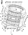
- a first embodiment of a cable gland according to the invention shown in Fig. 1 comprises a housing unit, designated as a whole by 10, which has a housing sleeve 12 which is provided at one end with a mounting projection 14 which can be screwed into a wall, for example a housing, by means of a thread 16.
- the housing sleeve 12 is provided with a rim 20 comprising wrench surfaces 18 and on a side of the rim 20 opposite the mounting lug 14 a sleeve section 22 extends, which carries an external thread 24 on its end facing away from the rim 20 a cap nut designated as a whole with 30 can be screwed on with an internal thread 32.
- the cap nut 30 likewise comprises a ring 34 with wrench flats 36 and an end opening 38 opposite the internal thread 32, to which an inner cone 40 adjoins, which lies between the opening 38 and the internal thread 32 inside the cap nut 30.
- the housing sleeve 12 and the cap nut 30 are preferably rotationally symmetrical to a central axis 42 of the housing unit, the inner cone surface 40 also being rotationally symmetrical to the central axis 42.
- the housing sleeve 12 and the cap nut 30 enclose an interior 44 of the housing unit 10 lying between the inner cone surface 40 and the mounting boss 14, which is accessible from the outside via the end opening 38 of the cap nut 30 and on the other hand via an end opening 46 enclosed by the mounting boss 14.
- a holding unit designated as a whole by 50, which comprises a guide sleeve 52 which also extends coaxially with the central axis 42 and on which two lamellar baskets 54 and 56, which likewise extend parallel to the central axis 42, extend on opposite sides connect, which are formed from individual spaced-apart slats 60 and 62, the slat foot 64 and 66 of which is held on the guide sleeve 52 and the slat end 68 and 70 of the end opening 38 in the cap nut 30 and the opening 46 in the Mounting approach 14 facing and thus movable in the radial direction to the central axis 42.
- each of the lamellar baskets 54 and 56 there is a clamping sealing ring 72 made of elastic material, the outer surface 74 of which is acted upon by the respective lamellas 60 and 62 and the inner surface 76 of which can be placed on a jacket of a cable guided through the holding unit 50 in the direction of the central axis 42 and can be pressed.
- the lamellae 60 can be placed with their lamella ends 68 on the inner cone surface 40 of the cap nut 30 and by the inner cone surface 40 when the cap nut 30 is screwed on and thus more axially Movement of the inner conical surface 40 in the direction of the mounting projection 14 can be moved radially inwards to the central axis 42, so that the inner surface 76 of the clamping sealing ring 72 can also be moved radially inwards to the central axis 42 by the lamellae 60 in order to have a cable extending through it through the clamping sealing ring 72 Clamp coat.
- a wedge ring 82 carrying an inner cone surface 80 is provided in the housing unit 10, which sits near the mounting projection 14, preferably at the height of the ring 20, so that the lamella ends 70 of the lamella 62 can be placed on the inner cone surface 80 and when the Lamellar basket 56 in the direction of the wedge ring 82, the lamellar ends 70 of the lamellas 62 can be moved radially inward with respect to the central axis 44, in order to also apply the clamping sealing ring 72 seated in this lamellar basket 56 radially inward to the central axis 42 and with its inner surface 76 on the casing to put through the cable 50 passed through the holding unit.
- the entire holding unit 50 together with the guide sleeve 52 and the lamellar baskets 54 and 56 can be freely displaced in the direction of the central axis 42 in the interior 44 of the housing unit 10.
- the distance between the inner cone surface 40, the cap nut 30 and the inner cone surface 80 of the wedge ring 82 can thus be shortened when the wedge ring 82 is stuck, so that when the lamella 60 is acted upon by the inner cone surface 40, the holding unit is displaced 50 in the sense of a
- the same is centered between the inner cone surfaces 40 and 80 and thus the fins 60 and 62 of both lamellar baskets 54 and 56 simultaneously move inward through the inner cone surfaces 40 and 80 radially to the central axis 42, preferably to the same extent, around the respective clamping sealing rings 72 to move radially inward to the central axis 42 and to place it on the jacket of a cable which is passed through the clamping sealing rings 72 of the lamellar baskets 54 and 56.
- clamping sealing rings 72 lie with their inner end sides 86 on sealing tabs 84 of the guide sleeve 52 in a tightly sealing manner, so that there is also a tight seal between the respective clamping sealing ring 72 of the respective disk basket 54 or 56 and the guide sleeve 52.
- the guide sleeve 52 is provided with receptacles 90 and 92 which are arranged at a distance from one another in the direction of the central axis 42 and into which sealing elements 94 and 96, preferably sealing rings, can be inserted.
- the receptacles 90 and 92 which are designed, for example, as circumferential grooves, and, on the other hand, bear against an inner surface 104 of the housing sleeve 12 with a sealing surface 100 or 102, which is radially outer with respect to the central axis 42, the inner surface 104 in the housing sleeve 12 by the external thread 24 extends up to a shoulder 106 provided at the level of the collar 20, against which the wedge ring 82 rests and is supported against further movement in the direction of the mounting projection 14.
- the inner surface 104 is designed as a cylindrical surface with respect to the central axis 42, so that the sealing elements 94 and 96 with their sealing surfaces 100 and 102 can slide along the inner surface 104 in the direction of the central axis 42 while maintaining a tight seal between the holding unit 50, the sealing elements 94 and 96 and the housing sleeve 12.
- the sealing elements 94, 96 comprise a soft-elastic core 110 and this is provided with a sliding layer 112 made of PTFE at least on its side projecting beyond the respective receptacle 90, 92 and forming the sealing surfaces 100 and 102, which is soft enough on the one hand to still ensure a tight seal with the inner surface 104, but on the other hand facilitates sliding of the respective sealing element 94 or 96 along the inner surface 104 in that the friction between the inner surface 104 and the respective sealing element 94 or 96 is reduced.
- sealing elements 94, 96 are dimensioned such that the core 110 of the same is deformed when the holding unit 50 is inserted into the housing sleeve 12, and the respective sealing surface 100 or 102 is thus applied to the inner surface 104 of the housing sleeve 12 radially outward.
- the guide sleeve 52 is in the direction parallel to the central axis 42 between the receptacle 90 and 92 and the corresponding lamella cage 54 and 56 following on the guide sleeve 52, a support shoulder 120 and 122 are provided, which have outer surfaces 124 and 126, which have a slightly smaller diameter than the inner surface 104.
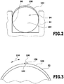
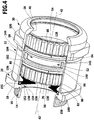
- the outer surfaces 124 and 126 are provided with elevations 128 and 130 which, as in FIG Fig. 3 shown, extend radially outward to the central axis 42, but due to their dimensioning can be partially removed mechanically, namely when the holding unit 50 is inserted into the housing sleeve 12, so that the elevations 128, 130 extend radially to the central axis 42 can independently adjust the exact diameter of the inner surface 104 by mechanical removal and thus support the support shoulders 120 and 122 precisely on the inner surface 104.
- the elevations 128, 130 preferably have a foot region 132 widened in a circumferential direction 134 of the support shoulders 120, 122, from which the extent of the elevations 128 and 130 in the circumferential direction 134 is reduced, so that in a tip region 136 of the elevations 128, 130 there is a minimal extension in the circumferential direction 134.
- the elevations 128, 130 can be removed more easily when the holding unit 50 is inserted into the housing sleeve 12, in particular the sleeve section 22, in the area of its tip 136 than in the foot area 132, so that it is ensured that each of the elevations 128, 130 is only in the minimum necessary dimension is removed, so that the respective support shoulder 120 or 122 is held and guided precisely in the inner surface 104 by the elevations 128 and 130 directly on the support surface 104.
- the elevations 128, 130 also have the advantage that, if they extend in particular in a rib-like manner in a direction running parallel to the central axis 42, they have little friction with the inner surface 104, so that they also slide in addition to a stable support the support shoulders 120, 122 is possible with the lowest possible frictional resistance.
- the guide sleeve 52 is also provided with an intermediate region 140, which in sections has wall regions 142 which are thinned in the radial direction with respect to the central axis 42 and which coincide with one another Alternate support webs 144 extending in the direction parallel to the central axis 42, so that there is sufficient stability in the intermediate region 140 on the one hand for supporting the lamella baskets 54, 56 against one another, in particular when the cap nut 30 is screwed on, and on the other hand a distortion in the manufacture of the guide sleeve 52 can be avoided. since the thinned areas 142 with the intermediate webs 144 allow a distortion-free and stable plastic configuration, in particular when the guide sleeve 52 is made of plastic.
- the support shoulders 120 and 122 with their elevations 128, 130 provide optimal support of the holding part 50 in the direction of the central axis 42 with the greatest possible distance guaranteed within the housing sleeve 12, in particular within the sleeve portion 22.
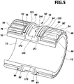
- a second embodiment of a cable gland according to the invention shown in Fig. 4 , Those elements that are identical to those of the first embodiment are provided with the same reference numerals, so that with regard to the description thereof, reference can be made in full to the explanations for the first embodiment.
- a shield contact element designated as a whole by 150, which has an annular carrier 152, from which starting bristles 154 extend radially inwards to the central axis 42 and a central opening 156 of the shield contact element 150 with their limit front ends.
- the contact bristles 154 are preferably fixed by a flat material 155, which also overlaps the ring-shaped carrier 152 and the contact bristles 154, which are essentially U-shaped around them, so that the contact bristles 154 extend on both sides of the carrier 152.
- the carrier 152 is preferably seated between the wedge ring 82 and a flange 158 of the housing sleeve 12 which carries the mounting projection 14 and which is preferably formed on the flange 20 in the region thereof.
- the carrier 152 is fixed with the flat material placed around it and carrying the contact bristles 154 between the wedge ring 82 and the flange 158, the wedge ring 82 preferably not fully resting on the shoulder 106 in this embodiment, but at a short distance from the shoulder 106 is positioned so that the force acting on the wedge ring 82 in the direction of the central axis 42 and in the direction of the mounting boss 14 can be used to support the carrier 152 with the flat material placed around it and forming the contact bristles 154 between the wedge ring 82 and the flange 158 to pinch, namely when the cap nut 30 is screwed onto the housing sleeve 12 and thus the holding unit 50 rests on the one hand with the lamellar basket 54 on the inner cone surface 40 and on
- the carrier 152 is preferably designed as a ring which is supported in its circumferential direction and acts in a radially resilient manner so that the carrier 152 with the flat material placed around it and forming the contact bristles 154 also follow in the radial direction to the central axis 154 bears on the outside on a contact surface 160 of the housing sleeve 12, which, because of the shoulder 106, has a slightly smaller diameter than the inner surface 104 of the housing sleeve 12.
- shield contact element 150 there is thus the additional possibility of contacting a cable shield of a cable which is passed through the cable bushing according to the invention and held by it, and of establishing an electrically conductive connection between the, for example, electrically conductive housing sleeve 12 and the cable shield by means of the shield contact element 150.
- the in Fig. 5 Holding unit 50 ' shown with regard to the design of the guide sleeve 52 and the lamellar baskets 54 and 56 constructed and constructed in the same manner as in the first and second exemplary embodiments.
- the clamping sealing rings 72 ' which are arranged in the lamellar baskets 54, 56, are not individual clamping sealing rings, but are connected to one another via a connecting piece 170 which extends between inner end sides 86' of the clamping sealing rings 72 ', and thereby runs in the direction parallel to the central axis 42 within the guide sleeve 52.
- clamping sealing rings 72 ′ form with the connecting piece 170 a sleeve-like part that is closed around the central axis 46 and also closed in the direction of the central axis 46, which encloses the lead-through cable and can be placed tightly against the cable in the area of the two clamping sealing rings, so that an optimal seal to the cable can be achieved.
- the two clamping sealing rings 72 ' are molded onto the plates 60, 62 of the plate baskets 54, 56 and the guide sleeve 52 by a two-component injection molding process and are thus fixed to them, this not affecting the function of the clamping sealing rings 72' that the clamping sealing rings 72 'in the lamellar baskets 54, 56 are effective in the same way as in the first and second exemplary embodiments, but with the difference that their manufacture as part of the holding unit 50' is simplified.
- openings 172 are preferably provided in the area of the receptacles 90 'and 92' for the sealing elements 94 'and 96', which also produce the sealing elements 94 'and 96' in the receptacles 90 'and 92' as part of a two-component injection molding process namely that they are connected to the clamping sealing rings 72 'and the connecting piece 170, so that the sealing elements 94' and 96 'can be produced from the same material as the clamping sealing rings 72' and the connecting piece 170.
- a holding unit 50 ' according to the third exemplary embodiment can be seen in the fact that it can be produced automatically in a simple manner, since the clamping sealing rings 72' do not have to be inserted into the lamellar baskets 54, 56 as finished parts.
- this exemplary embodiment has the advantage that an improved seal between the cable passing through and clamped by the holding unit 50 'and the holding unit 50', in particular the guide sleeve 52, is possible than in the first and second exemplary embodiments, since the two clamping sealing rings 72 'pass through the connecting piece 170 are also tightly connected to one another.
Landscapes
- Engineering & Computer Science (AREA)
- Architecture (AREA)
- Civil Engineering (AREA)
- Structural Engineering (AREA)
- Installation Of Indoor Wiring (AREA)
- Cable Accessories (AREA)
Claims (14)
- Raccord à vis pour câble comprenant
une unité formant boîtier (10) avec une douille de boîtier (12) et avec un écrou borgne (30) pouvant être installé par vissage sur la douille de boîtier (12)
et une unité de maintien (50) disposée dans l'unité formant boîtier (10) avec une douille de guidage (52), avec au moins un panier de lamelles (54, 56) s'étendant en partant de la douille de guidage (52) et avec une bague d'étanchéité de serrage (72) siégeant dans le panier de lamelles (54, 56) et pouvant être contrainte par celui-ci, composée d'un matériau élastique, laquelle peut être placée lorsque l'unité de maintien (50) est contrainte au moyen de l'unité formant boîtier (10) de manière hermétiquement étanche et serrée au niveau d'un câble guidé à travers l'unité formant boîtier (10) et l'unité de maintien (50) dans lequel l'unité de maintien (50) présente deux paniers de lamelles (54, 56), qui s'étendent sur des côtés opposés de la douille de guidage (52) en partant de celle-ci dans des directions opposées de manière parallèle par rapport à un axe central (42) de l'unité formant boîtier (10) et lesquels peuvent être contraints par l'unité formant boîtier (10), dans lequel siège, dans chaque panier de lamelles (54, 56), une bague d'étanchéité de serrage (72) élastique, qui peut être contrainte par le panier de lamelles (54, 56) respectif de manière radiale par rapport à l'axe central (42) en direction du câble guidé au travers, et dans lequel la douille de guidage (52) est pourvue d'un élément d'étanchéité (94, 96) agissant radialement, qui peut être placé de manière hermétiquement étanche avec une surface d'étanchéité (100, 102) au niveau d'une surface intérieure (104) cylindrique de la douille de boîtier (12). - Raccord à vis pour câble selon la revendication 1, caractérisé en ce que l'unité de maintien (50) est disposée dans l'unité formant boîtier (10) de manière à pouvoir être coulissée en direction d'un axe central (42) de l'unité formant boîtier (10).
- Raccord à vis pour câble selon l'une quelconque des revendications précédentes,
caractérisé en ce que l'unité de maintien (50) est disposée entre des surfaces de pression (40, 80), agissant respectivement sur un des paniers de lamelles (54, 56), de l'unité formant boîtier (10) et s'oriente conformément à une distance des surfaces de pression (40, 80) dans une direction parallèle par rapport à l'axe central (42) entre celles-ci. - Raccord à vis pour câble selon l'une quelconque des revendications précédentes,
caractérisé en ce que les bagues d'étanchéité de serrage (72) avec la douille de guidage (52) sont hermétiquement étanches. - Raccord à vis pour câble selon l'une quelconque des revendications précédentes,
caractérisé en ce que les bagues d'étanchéité de serrage (72') sont reliées les unes aux autres par une pièce de liaison (170). - Raccord à vis pour câble selon l'une quelconque des revendications précédentes,
caractérisé en ce que l'élément d'étanchéité (94, 96) est pourvu d'un revêtement glissant (112) supportant la surface d'étanchéité (100, 102). - Raccord à vis pour câble selon l'une quelconque des revendications précédentes,
caractérisé en ce que la douille de guidage (52) peut être placée avec deux éléments d'étanchéité (94, 96) agissant radialement de manière hermétiquement étanche au niveau de la surface intérieure (104) de la douille de boîtier (12). - Raccord à vis pour câble selon l'une quelconque des revendications précédentes,
caractérisé en ce que l'unité de maintien (50) est guidée dans la douille de boîtier (12) par des parties surélevées (128, 130) dépassant de la douille de guidage (52) dans une direction radiale par rapport à l'axe central (42). - Raccord à vis pour câble selon la revendication 8, caractérisé en ce que les parties surélevées (128, 130) reposent au niveau de la surface intérieure (104) cylindrique, servant de surface d'appui pour l'au moins un élément d'étanchéité (94, 96), de la douille de boîtier (12).
- Raccord à vis pour câble selon la revendication 8 ou 9, caractérisé en ce que les parties surélevées (128, 130) sont composées d'un matériau s'adaptant à une forme de la surface intérieure (104) par enlèvement de matériau et/ou par déformation lors de l'introduction de l'unité de maintien (50) dans l'unité formant boîtier (10).
- Raccord à vis pour câble selon l'une quelconque des revendications précédentes,
caractérisé en ce qu'un élément de contact de protection (150) est disposé dans l'unité formant boîtier (10). - Raccord à vis pour câble selon la revendication 11, caractérisé en ce que l'élément de contact de protection (150) est disposé dans un logement (158, 160), qui est prévu à proximité d'un embout de montage (14) de la douille de boîtier (12).
- Raccord à vis pour câble selon l'une quelconque des revendications précédentes, caractérisé en ce que les bagues d'étanchéité de serrage (72) forment dans les paniers de lamelles (54, 56), lors de la coopération de l'unité formant boîtier (10) et de l'unité de maintien (50), un élément élastique conservant le serrage et l'étanchéité.
- Raccord à vis pour câble selon la revendication 13, caractérisé en ce que les bagues d'étanchéité de serrage (72) forment les seuls éléments élastiques lors de la coopération de l'unité formant boîtier (10) et de l'unité de maintien (50).
Applications Claiming Priority (1)
| Application Number | Priority Date | Filing Date | Title |
|---|---|---|---|
| DE102008018176A DE102008018176A1 (de) | 2008-04-01 | 2008-04-01 | Kabelverschraubung |
Publications (3)
| Publication Number | Publication Date |
|---|---|
| EP2107657A2 EP2107657A2 (fr) | 2009-10-07 |
| EP2107657A3 EP2107657A3 (fr) | 2016-01-13 |
| EP2107657B1 true EP2107657B1 (fr) | 2020-01-08 |
Family
ID=40821802
Family Applications (1)
| Application Number | Title | Priority Date | Filing Date |
|---|---|---|---|
| EP09156372.6A Active EP2107657B1 (fr) | 2008-04-01 | 2009-03-26 | Dispositif de fixation de câble |
Country Status (2)
| Country | Link |
|---|---|
| EP (1) | EP2107657B1 (fr) |
| DE (1) | DE102008018176A1 (fr) |
Cited By (1)
| Publication number | Priority date | Publication date | Assignee | Title |
|---|---|---|---|---|
| DE102022130330A1 (de) | 2022-11-16 | 2024-05-16 | U.I. Lapp Gmbh | Vorrichtung zur Montage einer Kabelverschraubung |
Families Citing this family (4)
| Publication number | Priority date | Publication date | Assignee | Title |
|---|---|---|---|---|
| DE102012019758B4 (de) | 2012-10-09 | 2016-07-07 | Jacob Gmbh Elektrotechnische Fabrik | Vorrichtung zur Befestigung einer Leitung in einer Wandöffnung |
| EP3301770B1 (fr) * | 2016-10-01 | 2022-11-30 | Lapp Engineering AG | Presse-étoupe |
| EP3471225A1 (fr) | 2017-10-14 | 2019-04-17 | Lapp Engineering & Co. | Presse-étoupe |
| EP3598594B1 (fr) | 2018-07-21 | 2022-02-16 | Lapp Engineering AG | Presse-étoupe |
Family Cites Families (4)
| Publication number | Priority date | Publication date | Assignee | Title |
|---|---|---|---|---|
| US6069320A (en) * | 1993-07-30 | 2000-05-30 | Etcon Corporation | Cable splice protector |
| AT406619B (de) * | 1995-11-21 | 2000-07-25 | Wittmann Edith | Kabelverschraubung |
| DE19738517C1 (de) * | 1997-09-03 | 1998-11-19 | Hummel Anton Verwaltung | Kabelverschraubung für Erdungs- oder Abschirmkabel mit einem gegen das Kabel preßbaren Klemmeinsatz |
| US6639146B1 (en) * | 2002-06-26 | 2003-10-28 | Avc Industrial Corp. | EMI protective cable connector |
-
2008
- 2008-04-01 DE DE102008018176A patent/DE102008018176A1/de not_active Withdrawn
-
2009
- 2009-03-26 EP EP09156372.6A patent/EP2107657B1/fr active Active
Non-Patent Citations (1)
| Title |
|---|
| None * |
Cited By (1)
| Publication number | Priority date | Publication date | Assignee | Title |
|---|---|---|---|---|
| DE102022130330A1 (de) | 2022-11-16 | 2024-05-16 | U.I. Lapp Gmbh | Vorrichtung zur Montage einer Kabelverschraubung |
Also Published As
| Publication number | Publication date |
|---|---|
| EP2107657A3 (fr) | 2016-01-13 |
| DE102008018176A1 (de) | 2009-10-08 |
| EP2107657A2 (fr) | 2009-10-07 |
Similar Documents
| Publication | Publication Date | Title |
|---|---|---|
| EP1238451B1 (fr) | Corps d'etancheite pour garnitures de cable reparties en longueur | |
| EP2593997B1 (fr) | Dispositif de fixation d'un câble sur un raccord de départ de câble | |
| DE10021377C2 (de) | Rundsteckverbinder | |
| DE102010019600B4 (de) | Dichtelement | |
| EP3374085B1 (fr) | Rotor d'un séparateur centrifuge | |
| DE102012105258A1 (de) | Schirmhülse und Abschirmendelement umfassend eine Schirmhülse | |
| DE102010061067A1 (de) | Vorrichtung zur Fixierung eines Kabels an einen Kabelabgangsstutzen | |
| EP2107657B1 (fr) | Dispositif de fixation de câble | |
| DE2154082A1 (de) | Endmuffe für Hochspannungskabel | |
| WO2018141326A1 (fr) | Boîtier de connecteur enfichable | |
| DE102018216463A1 (de) | Verschaltungsanordnung für eine elektrische Maschine | |
| DE102005017690A1 (de) | Kabeldurchführung | |
| EP0475070A1 (fr) | Vanne à voies multiples | |
| EP2784880B1 (fr) | Passe-câble | |
| DE19941820C1 (de) | Sanitärarmatur | |
| WO2015044067A2 (fr) | Dispositif servant à la traversée étanche de lignes à travers un élément de séparation | |
| DE102013224461A1 (de) | Kugelgewindetrieb | |
| DE102010027444B3 (de) | Kabelzugentlastung und Dichtungssystem | |
| DE102015220685B4 (de) | Zugentlastungselement für eine Leitung, Aufnahmeeinrichtung, Zugentlastungsvorrichtung und Gehäuse | |
| EP1983629A1 (fr) | Presse-étoupe de câble | |
| DE102013105602A1 (de) | Anschlusselement für Steckverbinder | |
| EP2650576B1 (fr) | Raccord double pour la pose étanche de pièces longilignes | |
| EP3429041B1 (fr) | Presse-étoupe et connecteur enfichable doté d'une presse-étoupe | |
| DE19963905A1 (de) | Kabeldurchführung | |
| EP2982894B1 (fr) | Dispositif de serrage de tuyau |
Legal Events
| Date | Code | Title | Description |
|---|---|---|---|
| PUAI | Public reference made under article 153(3) epc to a published international application that has entered the european phase |
Free format text: ORIGINAL CODE: 0009012 |
|
| AK | Designated contracting states |
Kind code of ref document: A2 Designated state(s): AT BE BG CH CY CZ DE DK EE ES FI FR GB GR HR HU IE IS IT LI LT LU LV MC MK MT NL NO PL PT RO SE SI SK TR |
|
| AX | Request for extension of the european patent |
Extension state: AL BA RS |
|
| PUAL | Search report despatched |
Free format text: ORIGINAL CODE: 0009013 |
|
| AK | Designated contracting states |
Kind code of ref document: A3 Designated state(s): AT BE BG CH CY CZ DE DK EE ES FI FR GB GR HR HU IE IS IT LI LT LU LV MC MK MT NL NO PL PT RO SE SI SK TR |
|
| AX | Request for extension of the european patent |
Extension state: AL BA RS |
|
| RIC1 | Information provided on ipc code assigned before grant |
Ipc: H02G 3/06 20060101AFI20151208BHEP |
|
| 17P | Request for examination filed |
Effective date: 20160706 |
|
| RBV | Designated contracting states (corrected) |
Designated state(s): AT BE BG CH CY CZ DE DK EE ES FI FR GB GR HR HU IE IS IT LI LT LU LV MC MK MT NL NO PL PT RO SE SI SK TR |
|
| RBV | Designated contracting states (corrected) |
Designated state(s): AT BE BG CH CY CZ DE DK EE ES FI FR GB GR HR HU IE IS IT LI LT LU LV MC MK MT NL NO PL PT RO SE SI SK TR |
|
| AKX | Designation fees paid |
Designated state(s): AT BE BG CH CY CZ DE DK EE ES FI FR GB GR HR HU IE IS IT LI LT LU LV MC MK MT NL NO PL PT RO SE SI SK TR |
|
| AXX | Extension fees paid |
Extension state: AL Extension state: BA Extension state: RS |
|
| GRAP | Despatch of communication of intention to grant a patent |
Free format text: ORIGINAL CODE: EPIDOSNIGR1 |
|
| STAA | Information on the status of an ep patent application or granted ep patent |
Free format text: STATUS: GRANT OF PATENT IS INTENDED |
|
| INTG | Intention to grant announced |
Effective date: 20190801 |
|
| GRAS | Grant fee paid |
Free format text: ORIGINAL CODE: EPIDOSNIGR3 |
|
| GRAA | (expected) grant |
Free format text: ORIGINAL CODE: 0009210 |
|
| STAA | Information on the status of an ep patent application or granted ep patent |
Free format text: STATUS: THE PATENT HAS BEEN GRANTED |
|
| AK | Designated contracting states |
Kind code of ref document: B1 Designated state(s): AT BE BG CH CY CZ DE DK EE ES FI FR GB GR HR HU IE IS IT LI LT LU LV MC MK MT NL NO PL PT RO SE SI SK TR |
|
| REG | Reference to a national code |
Ref country code: GB Ref legal event code: FG4D Free format text: NOT ENGLISH |
|
| REG | Reference to a national code |
Ref country code: CH Ref legal event code: EP |
|
| REG | Reference to a national code |
Ref country code: DE Ref legal event code: R096 Ref document number: 502009016084 Country of ref document: DE |
|
| REG | Reference to a national code |
Ref country code: IE Ref legal event code: FG4D Free format text: LANGUAGE OF EP DOCUMENT: GERMAN |
|
| REG | Reference to a national code |
Ref country code: AT Ref legal event code: REF Ref document number: 1223856 Country of ref document: AT Kind code of ref document: T Effective date: 20200215 |
|
| REG | Reference to a national code |
Ref country code: NL Ref legal event code: MP Effective date: 20200108 |
|
| REG | Reference to a national code |
Ref country code: LT Ref legal event code: MG4D |
|
| PG25 | Lapsed in a contracting state [announced via postgrant information from national office to epo] |
Ref country code: FI Free format text: LAPSE BECAUSE OF FAILURE TO SUBMIT A TRANSLATION OF THE DESCRIPTION OR TO PAY THE FEE WITHIN THE PRESCRIBED TIME-LIMIT Effective date: 20200108 Ref country code: PT Free format text: LAPSE BECAUSE OF FAILURE TO SUBMIT A TRANSLATION OF THE DESCRIPTION OR TO PAY THE FEE WITHIN THE PRESCRIBED TIME-LIMIT Effective date: 20200531 Ref country code: NO Free format text: LAPSE BECAUSE OF FAILURE TO SUBMIT A TRANSLATION OF THE DESCRIPTION OR TO PAY THE FEE WITHIN THE PRESCRIBED TIME-LIMIT Effective date: 20200408 Ref country code: LT Free format text: LAPSE BECAUSE OF FAILURE TO SUBMIT A TRANSLATION OF THE DESCRIPTION OR TO PAY THE FEE WITHIN THE PRESCRIBED TIME-LIMIT Effective date: 20200108 Ref country code: NL Free format text: LAPSE BECAUSE OF FAILURE TO SUBMIT A TRANSLATION OF THE DESCRIPTION OR TO PAY THE FEE WITHIN THE PRESCRIBED TIME-LIMIT Effective date: 20200108 |
|
| PG25 | Lapsed in a contracting state [announced via postgrant information from national office to epo] |
Ref country code: BG Free format text: LAPSE BECAUSE OF FAILURE TO SUBMIT A TRANSLATION OF THE DESCRIPTION OR TO PAY THE FEE WITHIN THE PRESCRIBED TIME-LIMIT Effective date: 20200408 Ref country code: SE Free format text: LAPSE BECAUSE OF FAILURE TO SUBMIT A TRANSLATION OF THE DESCRIPTION OR TO PAY THE FEE WITHIN THE PRESCRIBED TIME-LIMIT Effective date: 20200108 Ref country code: LV Free format text: LAPSE BECAUSE OF FAILURE TO SUBMIT A TRANSLATION OF THE DESCRIPTION OR TO PAY THE FEE WITHIN THE PRESCRIBED TIME-LIMIT Effective date: 20200108 Ref country code: HR Free format text: LAPSE BECAUSE OF FAILURE TO SUBMIT A TRANSLATION OF THE DESCRIPTION OR TO PAY THE FEE WITHIN THE PRESCRIBED TIME-LIMIT Effective date: 20200108 Ref country code: GR Free format text: LAPSE BECAUSE OF FAILURE TO SUBMIT A TRANSLATION OF THE DESCRIPTION OR TO PAY THE FEE WITHIN THE PRESCRIBED TIME-LIMIT Effective date: 20200409 Ref country code: IS Free format text: LAPSE BECAUSE OF FAILURE TO SUBMIT A TRANSLATION OF THE DESCRIPTION OR TO PAY THE FEE WITHIN THE PRESCRIBED TIME-LIMIT Effective date: 20200508 |
|
| REG | Reference to a national code |
Ref country code: DE Ref legal event code: R097 Ref document number: 502009016084 Country of ref document: DE |
|
| PG25 | Lapsed in a contracting state [announced via postgrant information from national office to epo] |
Ref country code: SK Free format text: LAPSE BECAUSE OF FAILURE TO SUBMIT A TRANSLATION OF THE DESCRIPTION OR TO PAY THE FEE WITHIN THE PRESCRIBED TIME-LIMIT Effective date: 20200108 Ref country code: MC Free format text: LAPSE BECAUSE OF FAILURE TO SUBMIT A TRANSLATION OF THE DESCRIPTION OR TO PAY THE FEE WITHIN THE PRESCRIBED TIME-LIMIT Effective date: 20200108 Ref country code: CZ Free format text: LAPSE BECAUSE OF FAILURE TO SUBMIT A TRANSLATION OF THE DESCRIPTION OR TO PAY THE FEE WITHIN THE PRESCRIBED TIME-LIMIT Effective date: 20200108 Ref country code: RO Free format text: LAPSE BECAUSE OF FAILURE TO SUBMIT A TRANSLATION OF THE DESCRIPTION OR TO PAY THE FEE WITHIN THE PRESCRIBED TIME-LIMIT Effective date: 20200108 Ref country code: ES Free format text: LAPSE BECAUSE OF FAILURE TO SUBMIT A TRANSLATION OF THE DESCRIPTION OR TO PAY THE FEE WITHIN THE PRESCRIBED TIME-LIMIT Effective date: 20200108 Ref country code: EE Free format text: LAPSE BECAUSE OF FAILURE TO SUBMIT A TRANSLATION OF THE DESCRIPTION OR TO PAY THE FEE WITHIN THE PRESCRIBED TIME-LIMIT Effective date: 20200108 Ref country code: DK Free format text: LAPSE BECAUSE OF FAILURE TO SUBMIT A TRANSLATION OF THE DESCRIPTION OR TO PAY THE FEE WITHIN THE PRESCRIBED TIME-LIMIT Effective date: 20200108 |
|
| PLBE | No opposition filed within time limit |
Free format text: ORIGINAL CODE: 0009261 |
|
| STAA | Information on the status of an ep patent application or granted ep patent |
Free format text: STATUS: NO OPPOSITION FILED WITHIN TIME LIMIT |
|
| 26N | No opposition filed |
Effective date: 20201009 |
|
| REG | Reference to a national code |
Ref country code: BE Ref legal event code: MM Effective date: 20200331 |
|
| PG25 | Lapsed in a contracting state [announced via postgrant information from national office to epo] |
Ref country code: LU Free format text: LAPSE BECAUSE OF NON-PAYMENT OF DUE FEES Effective date: 20200326 |
|
| PG25 | Lapsed in a contracting state [announced via postgrant information from national office to epo] |
Ref country code: IE Free format text: LAPSE BECAUSE OF NON-PAYMENT OF DUE FEES Effective date: 20200326 Ref country code: IT Free format text: LAPSE BECAUSE OF FAILURE TO SUBMIT A TRANSLATION OF THE DESCRIPTION OR TO PAY THE FEE WITHIN THE PRESCRIBED TIME-LIMIT Effective date: 20200108 |
|
| PG25 | Lapsed in a contracting state [announced via postgrant information from national office to epo] |
Ref country code: SI Free format text: LAPSE BECAUSE OF FAILURE TO SUBMIT A TRANSLATION OF THE DESCRIPTION OR TO PAY THE FEE WITHIN THE PRESCRIBED TIME-LIMIT Effective date: 20200108 Ref country code: PL Free format text: LAPSE BECAUSE OF FAILURE TO SUBMIT A TRANSLATION OF THE DESCRIPTION OR TO PAY THE FEE WITHIN THE PRESCRIBED TIME-LIMIT Effective date: 20200108 Ref country code: BE Free format text: LAPSE BECAUSE OF NON-PAYMENT OF DUE FEES Effective date: 20200331 |
|
| PG25 | Lapsed in a contracting state [announced via postgrant information from national office to epo] |
Ref country code: MT Free format text: LAPSE BECAUSE OF FAILURE TO SUBMIT A TRANSLATION OF THE DESCRIPTION OR TO PAY THE FEE WITHIN THE PRESCRIBED TIME-LIMIT Effective date: 20200108 Ref country code: CY Free format text: LAPSE BECAUSE OF FAILURE TO SUBMIT A TRANSLATION OF THE DESCRIPTION OR TO PAY THE FEE WITHIN THE PRESCRIBED TIME-LIMIT Effective date: 20200108 |
|
| PG25 | Lapsed in a contracting state [announced via postgrant information from national office to epo] |
Ref country code: MK Free format text: LAPSE BECAUSE OF FAILURE TO SUBMIT A TRANSLATION OF THE DESCRIPTION OR TO PAY THE FEE WITHIN THE PRESCRIBED TIME-LIMIT Effective date: 20200108 |
|
| P01 | Opt-out of the competence of the unified patent court (upc) registered |
Effective date: 20230517 |
|
| PGFP | Annual fee paid to national office [announced via postgrant information from national office to epo] |
Ref country code: CH Payment date: 20250401 Year of fee payment: 17 |
|
| REG | Reference to a national code |
Ref country code: CH Ref legal event code: U11 Free format text: ST27 STATUS EVENT CODE: U-0-0-U10-U11 (AS PROVIDED BY THE NATIONAL OFFICE) Effective date: 20260401 |
|
| PGFP | Annual fee paid to national office [announced via postgrant information from national office to epo] |
Ref country code: GB Payment date: 20260324 Year of fee payment: 18 |
|
| PGFP | Annual fee paid to national office [announced via postgrant information from national office to epo] |
Ref country code: DE Payment date: 20260319 Year of fee payment: 18 |
|
| PGFP | Annual fee paid to national office [announced via postgrant information from national office to epo] |
Ref country code: AT Payment date: 20260320 Year of fee payment: 18 |
|
| PGFP | Annual fee paid to national office [announced via postgrant information from national office to epo] |
Ref country code: FR Payment date: 20260320 Year of fee payment: 18 |
|
| PGFP | Annual fee paid to national office [announced via postgrant information from national office to epo] |
Ref country code: TR Payment date: 20260323 Year of fee payment: 18 |