EP2107690B1 - Mobilkommunikationsendgerät und Verfahren zur Steuerung der Übertragungscharakteristik dafür - Google Patents
Mobilkommunikationsendgerät und Verfahren zur Steuerung der Übertragungscharakteristik dafür Download PDFInfo
- Publication number
- EP2107690B1 EP2107690B1 EP09156906.1A EP09156906A EP2107690B1 EP 2107690 B1 EP2107690 B1 EP 2107690B1 EP 09156906 A EP09156906 A EP 09156906A EP 2107690 B1 EP2107690 B1 EP 2107690B1
- Authority
- EP
- European Patent Office
- Prior art keywords
- transmission
- section
- characteristic
- country
- signal transmission
- Prior art date
- Legal status (The legal status is an assumption and is not a legal conclusion. Google has not performed a legal analysis and makes no representation as to the accuracy of the status listed.)
- Ceased
Links
- 230000005540 biological transmission Effects 0.000 title claims description 141
- 238000010295 mobile communication Methods 0.000 title claims description 11
- 238000000034 method Methods 0.000 title claims description 8
- 230000008859 change Effects 0.000 claims description 41
- 230000008054 signal transmission Effects 0.000 claims description 29
- 238000012544 monitoring process Methods 0.000 claims description 18
- 238000012545 processing Methods 0.000 description 43
- 230000005236 sound signal Effects 0.000 description 18
- 230000001413 cellular effect Effects 0.000 description 8
- 238000004891 communication Methods 0.000 description 8
- 230000007423 decrease Effects 0.000 description 5
- 230000009471 action Effects 0.000 description 4
- 230000033228 biological regulation Effects 0.000 description 4
- 238000010586 diagram Methods 0.000 description 3
- 230000005855 radiation Effects 0.000 description 3
- 230000006870 function Effects 0.000 description 2
- 238000002955 isolation Methods 0.000 description 2
- 238000005457 optimization Methods 0.000 description 2
- 230000004044 response Effects 0.000 description 2
- 230000002411 adverse Effects 0.000 description 1
- 230000008901 benefit Effects 0.000 description 1
- 238000013461 design Methods 0.000 description 1
- 230000006866 deterioration Effects 0.000 description 1
- 230000000694 effects Effects 0.000 description 1
- 230000006872 improvement Effects 0.000 description 1
- 238000012986 modification Methods 0.000 description 1
- 230000004048 modification Effects 0.000 description 1
- 230000010355 oscillation Effects 0.000 description 1
- 230000035945 sensitivity Effects 0.000 description 1
Images




Classifications
-
- H—ELECTRICITY
- H04—ELECTRIC COMMUNICATION TECHNIQUE
- H04B—TRANSMISSION
- H04B1/00—Details of transmission systems, not covered by a single one of groups H04B3/00 - H04B13/00; Details of transmission systems not characterised by the medium used for transmission
- H04B1/02—Transmitters
- H04B1/04—Circuits
- H04B1/0475—Circuits with means for limiting noise, interference or distortion
-
- H—ELECTRICITY
- H04—ELECTRIC COMMUNICATION TECHNIQUE
- H04B—TRANSMISSION
- H04B1/00—Details of transmission systems, not covered by a single one of groups H04B3/00 - H04B13/00; Details of transmission systems not characterised by the medium used for transmission
- H04B1/06—Receivers
- H04B1/16—Circuits
- H04B1/1646—Circuits adapted for the reception of stereophonic signals
-
- H—ELECTRICITY
- H04—ELECTRIC COMMUNICATION TECHNIQUE
- H04M—TELEPHONIC COMMUNICATION
- H04M1/00—Substation equipment, e.g. for use by subscribers
- H04M1/60—Substation equipment, e.g. for use by subscribers including speech amplifiers
- H04M1/6033—Substation equipment, e.g. for use by subscribers including speech amplifiers for providing handsfree use or a loudspeaker mode in telephone sets
- H04M1/6041—Portable telephones adapted for handsfree use
- H04M1/6058—Portable telephones adapted for handsfree use involving the use of a headset accessory device connected to the portable telephone
-
- H—ELECTRICITY
- H04—ELECTRIC COMMUNICATION TECHNIQUE
- H04M—TELEPHONIC COMMUNICATION
- H04M1/00—Substation equipment, e.g. for use by subscribers
- H04M1/72—Mobile telephones; Cordless telephones, i.e. devices for establishing wireless links to base stations without route selection
- H04M1/724—User interfaces specially adapted for cordless or mobile telephones
- H04M1/72403—User interfaces specially adapted for cordless or mobile telephones with means for local support of applications that increase the functionality
- H04M1/72409—User interfaces specially adapted for cordless or mobile telephones with means for local support of applications that increase the functionality by interfacing with external accessories
-
- Y—GENERAL TAGGING OF NEW TECHNOLOGICAL DEVELOPMENTS; GENERAL TAGGING OF CROSS-SECTIONAL TECHNOLOGIES SPANNING OVER SEVERAL SECTIONS OF THE IPC; TECHNICAL SUBJECTS COVERED BY FORMER USPC CROSS-REFERENCE ART COLLECTIONS [XRACs] AND DIGESTS
- Y02—TECHNOLOGIES OR APPLICATIONS FOR MITIGATION OR ADAPTATION AGAINST CLIMATE CHANGE
- Y02D—CLIMATE CHANGE MITIGATION TECHNOLOGIES IN INFORMATION AND COMMUNICATION TECHNOLOGIES [ICT], I.E. INFORMATION AND COMMUNICATION TECHNOLOGIES AIMING AT THE REDUCTION OF THEIR OWN ENERGY USE
- Y02D30/00—Reducing energy consumption in communication networks
- Y02D30/70—Reducing energy consumption in communication networks in wireless communication networks
Definitions
- the present invention relates to a mobile communication terminal, such as a mobile telephone terminal, etc., having a function of transmitting an FM radio wave, for example, and a method of controlling a transmission characteristic thereof.
- a transmission level of a transmitter (FM transmitter, etc.) built in a mobile telephone terminal is specified in a state of a single mobile telephone terminal, that is to say, in a state of not being connected with various kinds of accessory devices, for example such as an earphone, a hands-free set, a battery charger, etc.
- the transmission level is set so that a maximum transmission level is obtained within a range of not violating the Radio Law.
- a transmission level, a frequency band, further, approval/disapproval of transmission, etc., of the transmitter, such as an FM transmitter, to be mounted on a mobile telephone terminal are set in accordance with a specification of each country.
- Japanese Unexamined Patent Application Publication No. 2005-160022 ( Fig. 1 ) has disclosed a mobile telephone in which a connector of the mobile telephone is provided with a charging terminal and an antenna connection terminal, an external antenna cable is connected to the connector, and thereby a transmission/reception sensitivity of the mobile telephone has been improved, and charging the mobile telephone has become possible at the same time.
- JP 2007/019863A describes a prior art phone allowing an ear phone to be plugged in and the FM transmission output is altered accordingly.
- a transmission level and a frequency band is set in a state of not being connected with an accessory device. Also, approval/disapproval of transmission, the transmission level and the frequency band etc., are set in accordance with a specification of each country.
- the present invention has been made in view of these circumstances.
- a mobile terminal provided with a transmitter, such as an FM transmitter, etc.
- the above-described change in the use state occurs, for example, when an accessory device is connected to the terminal or a use country of the terminal is changed, or the like.
- a mobile communication terminal according to Claim 1.
- the transmission characteristic of the signal transmission section is best adjusted so as to offset the variation of the transmission characteristic caused by a change of the use state.
- the transmission characteristic of the signal transmission section is best adjusted in order to offset the variation of the transmission characteristic caused by the change of the use state.
- a mobile terminal provided with a transmitter, such as an FM transmitter, for example, it is possible to take effective measures when a change occurs in a use state of the terminal, and the terminal might violate regulations, such as the Radio Law. This situation occurs, for example, when an accessory device is connected to the terminal or a use country of the terminal is changed, or the like. Also, it is possible to allow reducing a change in the availability for the user in such a case.
- a mobile telephone terminal having a built-in transmitter such as an FM transmitter
- a transmitter is not limited to an FM transmitter, and may be a transmitter for proximity radio communication, for example a so-called Bluetooth (registered trademark), an UWB (Ultra Wide Band) system, a wireless LAN (Local Area Network), etc.
- Fig. 1 illustrates a schematic configuration of a mobile telephone terminal 1 according to a first embodiment.
- a mobile telephone terminal according to the first embodiment includes all the components included in a general mobile telephone terminal. However, some of the components are not shown in Fig. 1 , and only the configuration of main parts related to the present invention are shown.
- a system connector 2 is a connector to which various accessory devices 3, for example, an earphone, a hands-free set, a battery charger, a USB cable, etc., can be connected.
- the accessory device 3 has a device main unit and an external connector, and has a configuration in which the device main unit and the external connector are connected with a cable.
- the external connector of the accessory device 3 is connected to the system connector 2 of the mobile telephone terminal 1.
- a separate block 10 is a set of components (for example, various components, such as a communication circuit and an antenna for communicating with a mobile terminal network, an audio processing circuit, an image processing circuit, a display, etc.), which are represented as one block, excluding the components related to the present invention among all the components included in the mobile telephone terminal 1.
- An FM transmitter block 14 has a modulator 17 performing FM-modulation on an audio signal supplied from an audio processing circuit, not shown in the figure, through a terminal 15 and a variable gain amplifier (VGA) 18 adjusting the transmission level of the FM audio signal having been subjected to the FM modulation by the modulator 17.
- VGA variable gain amplifier
- components such as a local oscillator, a PLL circuit, etc., normally included in an FM transmitter, are not shown in the figure.
- the audio signal supplied from the terminal 15 is any one of the audio signals that are selected by the user and are instructed to be transmitted from the FM transmitter among various audio signals, for example, such as a playback music signal, a radio sound signal, a television audio signal, etc.
- the FM audio signal output from the FM transmitter block 14 is externally radiated from an FM antenna 16 built in the mobile telephone terminal 1 as an FM radio wave.
- the FM transmitter block 14 and the FM antenna 16 are built in the mobile telephone terminal 1, and thus share ground, etc., with the separate block 10 as a matter of course.
- a factory setting value of the transmission level of the FM transmitter block 14 of the mobile telephone terminal 1 is set to a predetermined level value (in the following, referred to as a default power value) in a state in which the accessory device 3, etc., are not connected to the system connector 2.
- a default power value is set so that a maximum transmission level is obtained within a range of not violating the Radio Law.
- the transmission level might change by a change in the antenna gain of the FM antenna 16. That is to say, if the accessory device 3 is connected to the system connector 2, ground of the mobile telephone terminal 1 is also connected to the cable of the accessory device 3 through the system connector 2.
- the connected cable affects the antenna gain of the FM antenna 16, and thus a radiation level of the FM antenna 16 varies (that is to say, the transmission level changes). In particular, if the transmission level becomes greater than the level specified by the Radio Law, a problem of violating the Radio Law arises.
- examples of simultaneous use of the transmission of the FM audio signal by the FM transmitter and the accessory device 3 are as follows.
- One example is the case of listening to a music using a hands-free set and, at the same time, transmitting a music signal from the FM transmitter to another radio receiver, etc.
- Another example is the case of charging the mobile telephone terminal 1 by a battery charger, and at the same time, transmitting a music signal from the FM transmitter to another radio receiver, etc.
- the mobile telephone terminal 1 has a configuration described below.
- An accessory detector 11 is connected to the system connector 2, and monitors a connection of the accessory device 3 to the system connector 2. That is to say, the accessory detector 11 is monitoring a change in resistance which arises when an external connector, etc., of the accessory device 3 is connected to the system connector 2.
- the accessory detector 11 detects a change in resistance, which arises by a connection of some kind of the accessory device 3 to the system connector 2
- the accessory detector 11 transmits a value indicating the change in the resistance to a CPU (Central Processing Unit) 13.
- CPU Central Processing Unit
- the CPU 13 When the CPU 13 receives the value indicating the change in the resistance from the accessory detector 11, the CPU recognizes the connection of the accessory device 3 to the system connector 2 by the change in the resistance. Also, the CPU recognizes what type of accessory device 3 is connected by the amount of change in the resistance, for example. That is to say, the CPU 13 is monitoring a change in the use state of the mobile telephone terminal 1, such as the connection of the accessory device 3 to the system connector 2.
- the accessory detector 11 may receive, for example, a specific ID (identification information) sent from the accessory device 3, and transfers the ID to the CPU 13 in addition to the monitoring of the resistance value as described above.
- a specific ID identification information
- the CPU 13 recognizes that the accessory device 3 has been connected to the system connector 2 by receiving the specific ID transferred from the accessory detector 11, and also recognizes the type of the accessory device 3 from the specific ID.
- the accessory detector 11 itself may determine that the accessory device 3 has been connected to the system connector 2 from a change in the resistance of the system connector 2 and the amount of that change, or a specific ID, etc., of the accessory device 3, and may send the information on the connection and the information of the type-determination result to the CPU 13.
- the CPU 13 When the CPU 13 recognizes the connection of the accessory device 3 to the system connector 2 as described above, and also recognizes the type of the accessory device 3, the CPU 13 refers to information provided in a memory 12 in advance.
- the information provided in the memory 12 is, for example a look-up table in which a type of accessory device and an adjustment value of a transmission level for each type of the accessory device are related.
- the adjustment value of the transmission level corresponds to a difference value (that is to say, the variation of the radiation level of the antenna) for the default power value of the FM transmitter block 14.
- the adjustment value of the transmission level is a gain adjustment value of the variable gain amplifier 18. That is to say, to put it another way, a gain adjustment value described in the look-up table in the memory 12 is a difference value from the default gain value of the variable gain amplifier 18 when the transmission level of the FM transmitter block 14 becomes the default power value.
- the adjustment value is set to lower the gain of the variable gain amplifier 18 by the amount corresponding to the amount of change in the transmission level.
- the type of the accessory device 3 connected to the system connector 2 is a device 3 which lowers the transmission level of the FM transmitter block 14 (lowers the antenna gain of the FM antenna 16)
- the adjustment value is set to raise the gain of the variable gain amplifier 18 by the amount corresponding to the amount of change in the transmission level.
- the CPU 13 adjusts the variable gain amplifier 18 of the FM transmitter block 14 by the gain adjustment value referenced from the memory 12 on the basis of the type of the accessory device 3. Accordingly, if the gain adjustment value referenced from the memory 12 is, for example, an adjustment value lowering the gain of the variable gain amplifier 18, the transmission level of the FM transmitter block 14 is lowered. On the other hand, if the gain adjustment value referenced from the memory 12 is, for example, an adjustment value raising the gain of the variable gain amplifier 18, the transmission level of the FM transmitter block 14 is raised.
- the transmission level of the FM transmitter block 14 can be substantially matched with the default power value. That is to say, by the present embodiment, even in the case where variation of the transmission characteristic occurs, such as a change in the transmission level of the FM transmitter block 14 by a change in the use state, such as a connection of the accessory device 3 to the system connector 2, it is possible to perform optimization control of the transmission characteristic so as to substantially match the transmission level with the default power value.
- the transmission level will not become greater than the level specified by the Radio Law, and on the contrary, the availability for the user will not decrease by the deterioration of he signal transmission quality caused by a decrease in the transmission level. That is to say, in the present embodiment, the transmission power is controlled in accordance with the type of the accessory device 3 connected to the system connector 2, and thus it is possible to ensure usability while conforming to the Radio Law. Also, it is not necessary to set a use limit on the accessory device 3, and thus it becomes possible to cover various cases.
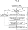
- Fig. 2 is a flowchart of connection monitoring processing of the accessory device 3 to the system connector 2, and transmission-power control processing at the time of connecting the accessory device 3 in the mobile telephone terminal 1 according to the first embodiment.
- a description will be given, as an example, of the case where the accessory detector 11 monitors the connection of the accessory device 3, and the CPU 13 determines the type of the accessory device 3.
- the accessory detector 11 monitors whether the accessory device 3 has been connected to the system connector 2 as processing of step S1. If the accessory device 3 is not connected to the system connector 2, the accessory detector 11 informs the CPU 13 of that fact. In this case, the CPU 13 sets the variable gain amplifier 18 of the FM transmitter block 14 to the default gain value. Thus, the transmission power of the FM transmitter block 14 becomes the default power value, and the FM antenna 16 transmits the FM audio signal at the default power value. After that, the accessory detector 11 continues to monitor the connection of the accessory device 3 as processing of step S5.
- the CPU 13 recognizes the type of the accessory device 3 on the basis of a signal, such as variation in resistance, a specific ID of the accessory device, or the like which is sent from the accessory detector 11 as processing of step S2.
- the CPU 13 refers to the look-up table in the memory 12 as processing of step S3, and thereby reads out a gain adjustment value corresponding to the variation of the antenna gain corresponding to the type of the accessory device 3.
- the CPU 13 controls the antenna radiation power of the FM antenna 16 by adjusting the variable gain amplifier 18 of the FM transmitter block 14 using the gain adjustment value as processing of step S4.
- the accessory detector 11 continues to monitor the connection of the accessory device 3 as processing of step S5.
- Fig. 3 illustrates a schematic configuration of a mobile telephone terminal 1 according to a second embodiment.
- the mobile telephone terminal according to the present embodiment includes all the components included in a general mobile telephone terminal. However, some of the components are not shown in Fig. 3 , and only the configuration of main parts related to the present invention are shown. Also, in Fig. 3 , the components that are substantially the same as those in Fig. 1 are marked with the same reference marks as those in Fig. 1 , and the detailed descriptions thereof will be omitted.
- a cellular block 30 is a communication circuit block for connecting to a mobile telephone network of various countries and performing communication through a communication antenna 31 for a mobile telephone network.
- a mobile-telephone communication method may differ for individual countries, and thus the cellular block 30 is capable of supporting mobile-telephone communication methods for the individual countries.
- a transmitter such as an FM transmitter, etc.
- standards such as transmission approval/disapproval, a transmission level, a frequency band, etc.
- transmission power control at the time of connecting the above-described accessory device 3. That is to say, for example, in a country in which transmission by a transmitter, such as an FM transmitter, etc., is prohibited, it is necessary to restrict use of the transmitter itself.
- transmission at a transmission level lower than the default power value it is necessary to lower the transmission level lower than the default power value.
- the mobile telephone terminal 1 has a configuration described below.
- the cellular block 30 When the cellular block 30 communicates with a base station of a mobile telephone network of a country in which the mobile telephone terminal 1 is used, the cellular block 30 obtains an identification code of that country, and transfers the country identification code to the CPU 13. Thus, the CPU 13 recognizes the country in which the mobile telephone terminal 1 is used.
- the cellular block 30, the FM transmitter block 14, and the FM antenna 16 are built in the mobile telephone terminal 1, and thus they all share ground as a matter of course.
- the CPU 13 recognizes the country in which the mobile telephone terminal 1 is used by the country identification code obtained last time and held in the memory 12, etc.
- the CPU 13 When the CPU 13 recognizes a country in which the mobile telephone terminal 1 is used as described above, the CPU refers to information provided in the memory 12 in advance.
- the memory 12 is provided with look-up tables in which each country identification code is related to transmission approval/disapproval information of each country, the transmission level value specified by the Radio Law of each country, the frequency band specified by the Radio Law of each country, etc.
- look-up tables with respect to each country in the memory 12 include, for example, a look-up table in which each country identification code and transmission approval/disapproval specified by the Radio Law of each country are related, a look-up table in which each country identification code and specified transmission power (specifically, the difference between the default power value and a specified transmission level value for each country) of the Radio Law of each country are related, and a look-up table in which each country identification code and specified transmission frequency band (or the difference between the default transmission frequency band and transmission frequency band for each country) of the Radio Law of each country identification code are related.
- the CPU 13 controls transmission approval/disapproval as follows by referring to the look-up table in which each country identification code and transmission approval/disapproval specified by the Radio Law of each country are related. If “transmission approval” is specified in a country in which the mobile telephone terminal 1 is used, the CPU 13 allows transmission from the FM transmitter block 14. If “transmission disapproval” is specified in a country in which the mobile telephone terminal 1 is used, the CPU 13 stops the FM transmitter block 14 to prohibit transmission. Also, the CPU 13 controls transmission power as follows by referring to the look-up table in which each country identification code and transmission power specified by the Radio Law of each country are related.
- the CPU 13 raises a level of the variable gain amplifier 18 of the FM transmitter block 14 to increase the transmission power (increase up to a maximum transmission level of the Radio Law in that country).
- the CPU 13 lowers a level of the variable gain amplifier 18 of the FM transmitter block 14 to decrease the transmission power (decrease within a maximum transmission level of the Radio Law in that country).
- the CPU 13 controls, for example, the modulator 17 (or an oscillation frequency of a local oscillator) of the FM transmitter block 14 to match the transmission frequency band and the number of frequency channels to the Radio Law of the country in which the mobile telephone terminal 1 is used by referring to the look-up table in which each country identification code and specified transmission frequency band of the Radio Law of each country are related.
- the CPU 13 controls to increase the wider frequency band and the number of frequency channels up to a maximum.
- the mobile telephone terminal 1 can satisfy the standards of the Radio Law in the country in which the mobile telephone terminal 1 is used. That is to say, by the present embodiment, even if it becomes necessary to change the transmission characteristic of the FM transmitter block 14 by a change in a use state, such as a change of a country in which the mobile telephone terminal is used, it is possible to perform optimization control of the transmission characteristic.
- the present embodiment for example, in a country in which use of a transmitter, such as an FM transmitter, etc., is prohibited, it is possible to prevent transmission, namely, violation of the Radio Law. Also, in a country in which use of a transmitter is allowed, it becomes possible to perform transmission at a maximum transmission level specified by the Radio Law in that country. In particular, in a country in which a maximum transmission level is set to be higher than the default power value, it is possible to extend a transmission distance farther than that of the case of transmitting at the default power value, thereby allowing improvement in the availability of the user. Also, in a country in which use of a transmitter is allowed, it becomes possible to transmit at the transmission frequency band specified by the Radio Law of that country.
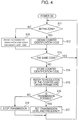
- Fig. 4 is a flowchart of recognition processing of a use country, and transmission control processing in accordance with the Radio Law of each country in the mobile telephone terminal 1 according to the second embodiment.
- a description will be given, as an example, of the case where the CPU 13 determines a use country by a country identification code, and sets transmission approval/disapproval, a transmission level, and a frequency in accordance with the use country.
- a control flow at the time of connecting an accessory is omitted.
- the cellular block 30 is monitoring whether the terminal is within a base station zone as processing of step S11. If the terminal is within the zone, the cellular block 30 obtains a country identification code by the communication with the base station as processing of step S12, and sends the obtained country identification code to the CPU 13.
- the cellular block 30 informs the CPU 13 of the fact.
- the CPU 13 reads out the country identification code held in the memory 12 as processing of step S18.
- step S13 the CPU 13 determines whether the country identification code obtained in step S12 or the country identification code read out in step S18 is the same as the country identification code recognized immediately before obtaining the country identification code is in step S12 or in step S18. If it is the same, the processing returns to step S11. If it is different, processing proceeds to step S14, and the country identification code is stored in the memory 12.
- the CPU 13 proceeds to processing of step S15.
- the CPU 13 refers to the above-described look-up table specified by the Radio Law of the country and provided in the memory 12 on the basis of the country identification code obtained in step S12 or step S18 to obtain parameters, such as the approval/disapproval information, the transmission level, and the transmission frequency, etc., which are specified by the Radio Law of that country.
- the CPU 13 determines whether transmission from a transmitter, such as an FM transmitter, etc., is allowed by the Radio Law of that country as processing of step S16 by checking the parameters referenced from the look-up table.
- step S19 the CPU 13 stops the FM transmitter block 14 to prohibit transmission, and returns processing to step S11.
- step S17 the CPU 13 sets the transmission level and the transmission frequency in accordance with the parameters referenced from the look-up table.
- the FM transmitter block 14 performs transmission at the transmission level and the transmission frequency that have been set. After that, the CPU 13 returns the processing to step S11.
- Fig. 5 illustrates a schematic configuration of a mobile telephone terminal 1 according to a third exemplary only embodiment.
- the mobile telephone terminal according to the present embodiment includes all the components included in a general mobile telephone terminal. However, some of the components are not shown in Fig. 5 , and only the configuration of main parts related to the present invention are shown. Also, in Fig. 5 , the components that are substantially the same as those in Fig. 1 are marked with the same reference marks as those in Fig. 1 , and the detailed descriptions thereof will be omitted.
- an FM receiver block 52 is, for example, an FM radio receiver.
- the FM receiver block 52 shares the FM antenna 16 with the FM transmitter block 14.
- An FM audio signal received by the FM receiver block 52 is output to the accessory device 3, such as an earphone connected to the system connector 2.
- the FM receiver block 52, the FM transmitter block 14, and the FM antenna 16 are built in the mobile telephone terminal 1, and thus they all share ground as a matter of course.
- the antenna gain of the FM antenna 16 changes in the same manner as described in the first embodiment, the transmission level from the FM transmitter block 14 might be changed.
- it is possible to restrain variation in the transmission power by performing transmission power control of the FM transmitter block 14 in response to the connection of the accessory device 3 in the same manner as the case of the first embodiment described before.
- the FM receiver block 52 shares one FM antenna 16 with the FM transmitter block 14 (transmitter)
- the mobile telephone terminal 1 has a configuration described below.
- a low noise amplifier (LNA) 57 and a diode switch 58 are disposed between the FM antenna 16 and the FM receiver block 52.
- a low dropout regulator (LDO) 53 supplies source power to the low noise amplifier 57 and the diode switch 58.
- the mobile telephone terminal 1 when the mobile telephone terminal 1 is in an operation mode of transmitting an FM audio signal from the FM transmitter block 14, if the CPU 13 receives information that the accessory device 3 has been connected from the accessory detector 11, the CPU 13 controls the low dropout regulator 53 to stop the supply of the source power to the low noise amplifier 57, and turns OFF the diode switch 58.
- the mode of transmitting the FM audio signal from the FM transmitter block 14 a path for the receiver may be disconnected all the time regardless of whether the accessory device 3 is connected or not.
- the accessory device 3 when the accessory device 3 is connected to the system connector 2, if there is a change in the use state so as to cause the FM transmitter block 14 to transmit an FM audio signal, it is possible to ensure conformity to the Radio Law and the usability by performing optimum control of the transmission characteristic in order to prevent variation of the transmission power caused by the connection of the accessory device 3 while ensuring isolation of the FM antenna 16 from the FM transmitter block 14 by disconnecting a path (path used by the receiver) from the FM antenna 16 to the FM transmitter block 14.
- Fig. 6 is a flowchart of connection monitoring processing of the accessory device 3 to the system connector 2, and receiver-path disconnection processing at the time of connecting the accessory device 3 in the mobile telephone terminal 1 according to the third exemplary only embodiment.
- a transmission power control flow at the time of connecting an accessory is omitted.
- the accessory detector 11 monitors whether the accessory device 3 is connected to the system connector 2 as processing of step S31. If the accessory device 3 is not connected to the system connector 2, the accessory detector 11 informs the CPU 13 of that fact. In this case, the CPU 13 sets the variable gain amplifier 18 of the FM transmitter block 14 to the default gain value. Thus, the transmission power of the FM transmitter block 14 becomes the default power value, and the FM antenna 16 transmits the FM audio signal at the default power value. After that, the accessory detector 11 continues to monitor the connection of the accessory device 3 as processing of step S33.
- step S32 the CPU 13 controls the low dropout regulator 53 to stop the supply of the source power to the low noise amplifier 57, and turns OFF the diode switch 58, thereby disconnecting a path between the FM receiver block 52 and FM antenna 16.
- the accessory detector 11 continues to monitor the connection of the accessory device 3 as processing of step S33.
- the mobile telephone terminal 1 provided with a transmitter, such as an FM transmitter, etc.
- a transmitter such as an FM transmitter, etc.
Landscapes
- Engineering & Computer Science (AREA)
- Computer Networks & Wireless Communication (AREA)
- Signal Processing (AREA)
- Telephone Function (AREA)
- Transmitters (AREA)
- Mobile Radio Communication Systems (AREA)
- Transceivers (AREA)
Claims (6)
- Mobilkommunikationsendgerät (1), umfassend:einen Signalübertragungsabschnitt mit einem vorab festgelegten Standardwert für eine Übertragungscharakteristik;eine Antenne (16), die wenigstens vom Signalübertragungsabschnitt zu verwenden ist;einen separaten Schaltungsabschnitt (10), der mit der Erde des Signalübertragungsabschnitts und der Antenne verbunden ist und sich vom Signalübertragungsabschnitt unterscheidet;einen Überwachungsabschnitt (11), der dafür ausgelegt ist, eine Änderung eines Verwendungszustands des Endgeräts im Zusammenhang mit dem separaten Schaltungsabschnitt zu überwachen; undwenn der Signalübertragungsabschnitt (14) dafür ausgelegt ist, ein Signal mithilfe der Antenne zu übertragen, falls der Überwachungsabschnitt (11) eine Änderung des Verwendungszustands des Endgeräts erkennt,ist ein Abschnitt zum Verstellen der Übertragungscharakteristik dafür ausgelegt, eine Übertragungscharakteristik des Signalübertragungsabschnitts vom Standardwert auf eine Charakteristik zu verstellen, die für den Verwendungszustand optimiert ist,wobei der separate Schaltungsabschnitt (10) dafür ausgelegt ist, Informationen zu beschaffen, die ein Verwendungsland oder eine Verwendungsregion des Endgeräts angeben,der Überwachungsabschnitt (11) dafür ausgelegt ist, eine Änderung des Verwendungszustands des Endgeräts durch eine Änderung der durch den separaten Schaltungsabschnitt beschafften Informationen, die ein Verwendungsland oder eine Verwendungsregion angeben, zu überwachen, undwenn der Überwachungsabschnitt (11) dafür ausgelegt ist, eine Änderung der Informationen, die ein Verwendungsland oder eine Verwendungsregion angeben, zu erkennen, der Abschnitt zum Verstellen der Übertragungscharakteristik dafür ausgelegt ist, eine Übertragungscharakteristik des Signalübertragungsabschnitts vom Standardwert auf eine Charakteristik zu verstellen, die für den Verwendungszustand im Verwendungsland oder in der Verwendungsregion optimiert ist.
- Mobilkommunikationsendgerät gemäß Anspruch 1,
wobei der Überwachungsabschnitt (11) dafür ausgelegt ist, eine Änderung eines Verwendungszustands, die durch Anschluss eines externen Zubehörs an den separaten Schaltungsabschnitt (10) verursacht wurde, zu überwachen, und
der Abschnitt zum Verstellen der Übertragungscharakteristik dafür ausgelegt ist, die Übertragungscharakteristik des Signalübertragungsabschnitts gemäß einer Differenz zwischen der Übertragungscharakteristik des Signalübertragungsabschnitts und der Antenne, die durch den Anschluss des externen Zubehörs an den separaten Schaltungsabschnitt geändert werden soll, und dem Standardwert zu verstellen. - Mobilkommunikationsendgerät gemäß Anspruch 2,
wobei der Abschnitt zum Verstellen der Übertragungscharakteristik dafür ausgelegt ist, die Übertragungsleistungscharakteristik des Signalübertragungsabschnitts gemäß einer Differenz zwischen der Übertragungsleistungscharakteristik des Signalübertragungsabschnitts und der Antenne, die durch den Anschluss des externen Zubehörs an den separaten Schaltungsabschnitt geändert werden soll, und einer Standard-Übertragungsleistungscharakteristik, die im Voraus als Standardwert festgelegt wurde, zu verstellen. - Mobilkommunikationsendgerät gemäß Anspruch 1,
wobei der Abschnitt zum Verstellen der Übertragungscharakteristik dafür ausgelegt ist, eine Übertragungsleistungscharakteristik des Signalübertragungsabschnitts gemäß einer Differenz zwischen der Übertragungsleistungscharakteristik des Signalübertragungsabschnitts und der Antenne, die für das Verwendungsland oder die Verwendungsregion festgelegt wurde, und einer Standard-Übertragungsleistungscharakteristik, die im Voraus als Standardwert festgelegt wurde, zu verstellen. - Mobilkommunikationsendgerät gemäß Anspruch 1,
wobei der Abschnitt zum Verstellen der Übertragungscharakteristik dafür ausgelegt ist, eine Übertragungsfrequenzcharakteristik des Signalübertragungsabschnitts und der Antenne von der Standard-Übertragungsfrequenzcharakteristik, die im Voraus als Standardwert festgelegt wurde, auf eine Übertragungsfrequenzcharakteristik des Signalübertragungsabschnitts und der Antenne für das Verwendungsland oder die Verwendungsregion zu verstellen. - Verfahren zum Steuern einer Übertragungscharakteristik eines Mobilkommunikationsendgeräts mit einem Signalübertragungsabschnitt mit einem vorab festgelegten Standardwert für eine Übertragungscharakteristik, einer Antenne, die wenigstens vom Signalübertragungsabschnitt zu verwenden ist, und einem separaten Schaltungsabschnitt, der mit der Erde des Signalübertragungsabschnitts und der Antenne verbunden ist und sich vom Signalübertragungsabschnitt unterscheidet, wobei das Verfahren folgende Schritte umfasst:einen Überwachungsabschnitt, der eine Änderung eines Verwendungszustands des Endgeräts im Zusammenhang mit dem separaten Schaltungsabschnitt überwacht; undwenn der Signalübertragungsabschnitt ein Signal mithilfe der Antenne überträgt, falls der Überwachungsabschnitt eine Änderung des Verwendungszustands des Endgeräts erkennt, ein Abschnitt zum Verstellen der Übertragungscharakteristik eine Übertragungscharakteristik des Signalübertragungsabschnitts vom Standardwert auf eine Charakteristik verstellt, die für den Verwendungszustand optimiert ist,wobei der separate Schaltungsabschnitt (10) Informationen beschafft, die ein Verwendungsland oder eine Verwendungsregion des Endgeräts angeben,der Überwachungsabschnitt (11) eine Änderung des Verwendungszustands des Endgeräts durch eine Änderung der durch den separaten Schaltungsabschnitt beschafften Informationen, die ein Verwendungsland oder eine Verwendungsregion angeben, überwacht, undwenn der Überwachungsabschnitt (11) eine Änderung der Informationen, die ein Verwendungsland oder eine Verwendungsregion angeben, erkennt, der Abschnitt zum Verstellen der Übertragungscharakteristik eine Übertragungscharakteristik des Signalübertragungsabschnitts vom Standardwert auf eine Charakteristik verstellt, die für den Verwendungszustand im Verwendungsland oder in der Verwendungsregion optimiert ist.
Applications Claiming Priority (1)
| Application Number | Priority Date | Filing Date | Title |
|---|---|---|---|
| JP2008096663A JP2009253479A (ja) | 2008-04-02 | 2008-04-02 | 携帯通信端末及びその送信特性制御方法 |
Publications (3)
| Publication Number | Publication Date |
|---|---|
| EP2107690A2 EP2107690A2 (de) | 2009-10-07 |
| EP2107690A3 EP2107690A3 (de) | 2014-03-19 |
| EP2107690B1 true EP2107690B1 (de) | 2018-01-10 |
Family
ID=40802072
Family Applications (1)
| Application Number | Title | Priority Date | Filing Date |
|---|---|---|---|
| EP09156906.1A Ceased EP2107690B1 (de) | 2008-04-02 | 2009-03-31 | Mobilkommunikationsendgerät und Verfahren zur Steuerung der Übertragungscharakteristik dafür |
Country Status (4)
| Country | Link |
|---|---|
| US (1) | US8086268B2 (de) |
| EP (1) | EP2107690B1 (de) |
| JP (1) | JP2009253479A (de) |
| CN (1) | CN101552616B (de) |
Families Citing this family (28)
| Publication number | Priority date | Publication date | Assignee | Title |
|---|---|---|---|---|
| US8200172B2 (en) * | 2008-07-30 | 2012-06-12 | Monster Cable Products, Inc. | Look-up table for control of power output from FM transmitters |
| US8806041B1 (en) | 2010-12-15 | 2014-08-12 | Amazon Technologies, Inc. | Client device connectivity with integrated business rules and multiple network types |
| US9197617B1 (en) * | 2010-12-15 | 2015-11-24 | Amazon Technologies, Inc. | Client device connectivity with integrated business rules |
| KR101778528B1 (ko) * | 2011-02-16 | 2017-09-15 | 삼성전자 주식회사 | 안테나를 구비하는 통신 단말기의 송신 방법 및 장치 |
| US8909282B2 (en) | 2011-03-04 | 2014-12-09 | Qualcomm Incorporated | Systems and methods for dynamic transmission power limit back-off for specific absorption rate compliance |
| US8781437B2 (en) | 2011-03-04 | 2014-07-15 | Qualcomm Incorporated | Systems and methods for dynamic transmission power limit back-off for specific absorption rate compliance |
| CN102308562A (zh) * | 2011-07-25 | 2012-01-04 | 华为终端有限公司 | 移动终端的控制方法、装置、系统和移动终端 |
| US9204402B2 (en) * | 2012-04-06 | 2015-12-01 | Apple Inc. | Methods and apparatus for location-based parametric control |
| JP5662380B2 (ja) * | 2012-06-08 | 2015-01-28 | レノボ・シンガポール・プライベート・リミテッド | 無線端末装置のアンテナ出力を制御する方法、コンピュータ・プログラムおよび無線端末装置 |
| US9882995B2 (en) * | 2012-06-25 | 2018-01-30 | Sonos, Inc. | Systems, methods, apparatus, and articles of manufacture to provide automatic wireless configuration |
| EP2713632A1 (de) * | 2012-09-28 | 2014-04-02 | GN Netcom A/S | Konfigurieren einer drahtlosen Kommunikationsvorrichtung in einem mobilen Kommunikationssystem |
| US9124677B2 (en) * | 2012-11-23 | 2015-09-01 | Htc Corporation | Systems involving portable electronic devices and related methods |
| US9042845B2 (en) | 2012-11-30 | 2015-05-26 | Motorola Solutions, Inc. | Apparatus and method for detecting radio accessories |
| US9871544B2 (en) * | 2013-05-29 | 2018-01-16 | Microsoft Technology Licensing, Llc | Specific absorption rate mitigation |
| US10893488B2 (en) | 2013-06-14 | 2021-01-12 | Microsoft Technology Licensing, Llc | Radio frequency (RF) power back-off optimization for specific absorption rate (SAR) compliance |
| JP2015012363A (ja) * | 2013-06-27 | 2015-01-19 | ソニー株式会社 | 通信装置及び検出方法 |
| US9813997B2 (en) | 2014-01-10 | 2017-11-07 | Microsoft Technology Licensing, Llc | Antenna coupling for sensing and dynamic transmission |
| US10044095B2 (en) | 2014-01-10 | 2018-08-07 | Microsoft Technology Licensing, Llc | Radiating structure with integrated proximity sensing |
| US9769769B2 (en) | 2014-06-30 | 2017-09-19 | Microsoft Technology Licensing, Llc | Detecting proximity using antenna feedback |
| US9785174B2 (en) | 2014-10-03 | 2017-10-10 | Microsoft Technology Licensing, Llc | Predictive transmission power control for back-off |
| US9871545B2 (en) | 2014-12-05 | 2018-01-16 | Microsoft Technology Licensing, Llc | Selective specific absorption rate adjustment |
| WO2016136648A1 (ja) * | 2015-02-25 | 2016-09-01 | 京セラ株式会社 | ネットワーク装置 |
| JP6696964B2 (ja) * | 2015-02-25 | 2020-05-20 | 京セラ株式会社 | ネットワーク装置及びユーザ端末 |
| US9807704B2 (en) * | 2015-03-30 | 2017-10-31 | Ford Global Technologies, Llc | Key fob transmission compensation |
| US10013038B2 (en) | 2016-01-05 | 2018-07-03 | Microsoft Technology Licensing, Llc | Dynamic antenna power control for multi-context device |
| US10461406B2 (en) | 2017-01-23 | 2019-10-29 | Microsoft Technology Licensing, Llc | Loop antenna with integrated proximity sensing |
| US10224974B2 (en) | 2017-03-31 | 2019-03-05 | Microsoft Technology Licensing, Llc | Proximity-independent SAR mitigation |
| CN109391904B (zh) * | 2018-10-11 | 2021-06-22 | 深圳市万普拉斯科技有限公司 | Sar调整方法、装置、移动终端及可读存储介质 |
Family Cites Families (17)
| Publication number | Priority date | Publication date | Assignee | Title |
|---|---|---|---|---|
| US6021317A (en) * | 1997-04-30 | 2000-02-01 | Ericsson Inc. | Dual antenna radiotelephone systems including an antenna-management matrix switch and associated methods of operation |
| US6556825B1 (en) * | 2000-02-08 | 2003-04-29 | Sharp Laboratories Of America, Inc. | Method and apparatus for automatic adaptation of communications systems to regional spectrum variations |
| CN1408147A (zh) * | 2000-10-04 | 2003-04-02 | 三菱电机株式会社 | 无线通信机 |
| DE10251465A1 (de) * | 2002-11-05 | 2004-05-19 | Siemens Ag | Verfahren zum Sendeleistungsabgleich bei einem mobilen Kommunikationsendgerät und Kommunikationsendgerät zur Durchführung des Verfahrens |
| JP2004274723A (ja) * | 2003-02-17 | 2004-09-30 | Sony Corp | 無線通信システム、無線通信装置及び無線通信方法 |
| JP2005176302A (ja) * | 2003-09-26 | 2005-06-30 | Nec Access Technica Ltd | 携帯端末のアンテナ装置および放送波を受信可能な無線機 |
| JP2005160022A (ja) | 2003-10-29 | 2005-06-16 | Takanori Kato | 携帯電話機用アンテナ |
| US7177667B2 (en) * | 2003-11-25 | 2007-02-13 | Kmw Inc. | Antenna remote control apparatus of mobile communication base station system |
| JP2006041826A (ja) * | 2004-07-26 | 2006-02-09 | Matsushita Electric Ind Co Ltd | 携帯電話装置 |
| KR100677370B1 (ko) * | 2004-10-26 | 2007-02-02 | 엘지전자 주식회사 | 이동 통신 단말기의 안테나 매칭 장치 및 그 방법 |
| JP4616094B2 (ja) * | 2005-07-07 | 2011-01-19 | 京セラ株式会社 | 携帯電話機 |
| US8228865B2 (en) * | 2006-04-07 | 2012-07-24 | Qualcomm Incorporated | Method and apparatus for operating in a wireless local area network based on information from a wireless wide area network |
| US20080004081A1 (en) * | 2006-06-29 | 2008-01-03 | Paul Stanley Rutkowski | Apparatus and method for adapting a portable device operating mode |
| US8131205B2 (en) * | 2008-05-01 | 2012-03-06 | Michael Rosen | Mobile phone detection and interruption system and method |
| JP4888029B2 (ja) | 2006-10-11 | 2012-02-29 | 株式会社ニコン | ズームレンズ、撮像装置、ズームレンズの変倍方法 |
| WO2009001154A1 (en) * | 2007-06-28 | 2008-12-31 | Nokia Corporation | Radiated power optimization for a mobile radio transmitter/receiver having an antenna |
| JP4953993B2 (ja) * | 2007-08-31 | 2012-06-13 | 京セラ株式会社 | 携帯通信端末、送信電力切換方法および送信電力切換プログラム |
-
2008
- 2008-04-02 JP JP2008096663A patent/JP2009253479A/ja active Pending
-
2009
- 2009-03-27 US US12/412,852 patent/US8086268B2/en not_active Expired - Fee Related
- 2009-03-31 EP EP09156906.1A patent/EP2107690B1/de not_active Ceased
- 2009-04-02 CN CN2009101330489A patent/CN101552616B/zh not_active Expired - Fee Related
Non-Patent Citations (1)
| Title |
|---|
| None * |
Also Published As
| Publication number | Publication date |
|---|---|
| EP2107690A3 (de) | 2014-03-19 |
| CN101552616B (zh) | 2012-07-04 |
| US20090253459A1 (en) | 2009-10-08 |
| CN101552616A (zh) | 2009-10-07 |
| EP2107690A2 (de) | 2009-10-07 |
| JP2009253479A (ja) | 2009-10-29 |
| US8086268B2 (en) | 2011-12-27 |
Similar Documents
| Publication | Publication Date | Title |
|---|---|---|
| EP2107690B1 (de) | Mobilkommunikationsendgerät und Verfahren zur Steuerung der Übertragungscharakteristik dafür | |
| US8208886B2 (en) | Method and system for optimizing an FM transmitter and FM receiver in a single chip FM transmitter and FM receiver system | |
| US8046024B2 (en) | Multi-radio platform with WiMax and bluetooth radio modules and method | |
| US20050009576A1 (en) | Portable wireless communication device and methods of configuring same when connected to a vehicle | |
| EP2186377B1 (de) | Auf dem zuständigkeitsbereich basierende parametereinstellung für drahtlose sender/empfänger | |
| EP2597913B1 (de) | Verfahren und vorrichtung zur steuerung von signalübertragungen | |
| US5995813A (en) | Radio telephone and independently controlled booster | |
| US20040203789A1 (en) | Location service assisted transition between wireless networks | |
| US20150024696A1 (en) | Mobile terminal for automatically adjusting antenna matching and control method therefor | |
| CN101689892A (zh) | 用于具有天线的移动无线电发射机/接收机的辐射功率优化 | |
| EP2641434B1 (de) | Verfahren und vorrichtung zur einstellung einer übertragungsleistungsstufe | |
| US20220069926A1 (en) | Automatic signal strength indicator and automatic antenna switch | |
| WO2007014982A1 (en) | Method of controlling linearity in communications system, terminal device, and receiver | |
| US10091742B2 (en) | Wireless communication device | |
| EP3142189B1 (de) | Antenneneinstellungsverfahren auf basis eines variablen kondensators und entsprechende vorrichtung | |
| CN115149974A (zh) | 一种移动终端的控制方法及移动终端 | |
| US10181832B1 (en) | Multimode transmit power control loop, electronic device, and method of adjusting a detected operating level of amplified power output | |
| US20120244854A1 (en) | Mobile Communication Terminal and Communication Method Thereof | |
| US20200266765A1 (en) | Method and Apparatus for Providing Selective Pre-Signal Amplifier, Supply Power Conditioning | |
| GB2594363A (en) | Electronic device that limits electro-magnetic emissions from multiple batteries | |
| RU2465738C2 (ru) | Мобильные устройства связи с внутренними антеннами | |
| JPWO1994018761A1 (ja) | 無線電話装置 |
Legal Events
| Date | Code | Title | Description |
|---|---|---|---|
| PUAI | Public reference made under article 153(3) epc to a published international application that has entered the european phase |
Free format text: ORIGINAL CODE: 0009012 |
|
| 17P | Request for examination filed |
Effective date: 20090331 |
|
| AK | Designated contracting states |
Kind code of ref document: A2 Designated state(s): AT BE BG CH CY CZ DE DK EE ES FI FR GB GR HR HU IE IS IT LI LT LU LV MC MK MT NL NO PL PT RO SE SI SK TR |
|
| AX | Request for extension of the european patent |
Extension state: AL BA RS |
|
| RAP1 | Party data changed (applicant data changed or rights of an application transferred) |
Owner name: SONY MOBILE COMMUNICATIONS JAPAN, INC. |
|
| RIC1 | Information provided on ipc code assigned before grant |
Ipc: H04W 48/16 20090101ALN20131115BHEP Ipc: H04W 28/18 20090101ALN20131115BHEP Ipc: H04B 1/18 20060101AFI20131115BHEP Ipc: H04W 88/06 20090101ALI20131115BHEP Ipc: H04M 1/21 20060101ALI20131115BHEP Ipc: H04M 1/725 20060101ALI20131115BHEP Ipc: H04W 84/04 20090101ALN20131115BHEP Ipc: H04B 1/16 20060101ALI20131115BHEP Ipc: H04B 1/04 20060101ALI20131115BHEP |
|
| PUAL | Search report despatched |
Free format text: ORIGINAL CODE: 0009013 |
|
| AK | Designated contracting states |
Kind code of ref document: A3 Designated state(s): AT BE BG CH CY CZ DE DK EE ES FI FR GB GR HR HU IE IS IT LI LT LU LV MC MK MT NL NO PL PT RO SE SI SK TR |
|
| AX | Request for extension of the european patent |
Extension state: AL BA RS |
|
| RIC1 | Information provided on ipc code assigned before grant |
Ipc: H04W 48/16 20090101ALN20140213BHEP Ipc: H04M 1/725 20060101ALI20140213BHEP Ipc: H04B 1/04 20060101ALI20140213BHEP Ipc: H04W 28/18 20090101ALN20140213BHEP Ipc: H04M 1/21 20060101ALI20140213BHEP Ipc: H04B 1/18 20060101AFI20140213BHEP Ipc: H04B 1/16 20060101ALI20140213BHEP Ipc: H04W 88/06 20090101ALI20140213BHEP Ipc: H04W 84/04 20090101ALN20140213BHEP Ipc: H04M 1/60 20060101ALI20140213BHEP |
|
| 17Q | First examination report despatched |
Effective date: 20140304 |
|
| AKX | Designation fees paid |
Designated state(s): DE FR GB |
|
| STAA | Information on the status of an ep patent application or granted ep patent |
Free format text: STATUS: EXAMINATION IS IN PROGRESS |
|
| GRAP | Despatch of communication of intention to grant a patent |
Free format text: ORIGINAL CODE: EPIDOSNIGR1 |
|
| STAA | Information on the status of an ep patent application or granted ep patent |
Free format text: STATUS: GRANT OF PATENT IS INTENDED |
|
| RIC1 | Information provided on ipc code assigned before grant |
Ipc: H04W 28/18 20090101ALN20170711BHEP Ipc: H04W 84/04 20090101ALN20170711BHEP Ipc: H04M 1/725 20060101ALI20170711BHEP Ipc: H04B 1/04 20060101ALI20170711BHEP Ipc: H04W 48/16 20090101ALN20170711BHEP Ipc: H04B 1/18 20060101AFI20170711BHEP Ipc: H04M 1/21 20060101ALI20170711BHEP Ipc: H04M 1/60 20060101ALI20170711BHEP Ipc: H04B 1/16 20060101ALI20170711BHEP Ipc: H04W 88/06 20090101ALI20170711BHEP |
|
| INTG | Intention to grant announced |
Effective date: 20170728 |
|
| RAP1 | Party data changed (applicant data changed or rights of an application transferred) |
Owner name: SONY MOBILE COMMUNICATIONS INC. |
|
| GRAS | Grant fee paid |
Free format text: ORIGINAL CODE: EPIDOSNIGR3 |
|
| GRAA | (expected) grant |
Free format text: ORIGINAL CODE: 0009210 |
|
| STAA | Information on the status of an ep patent application or granted ep patent |
Free format text: STATUS: THE PATENT HAS BEEN GRANTED |
|
| AK | Designated contracting states |
Kind code of ref document: B1 Designated state(s): DE FR GB |
|
| REG | Reference to a national code |
Ref country code: GB Ref legal event code: FG4D |
|
| REG | Reference to a national code |
Ref country code: DE Ref legal event code: R096 Ref document number: 602009050285 Country of ref document: DE |
|
| REG | Reference to a national code |
Ref country code: FR Ref legal event code: PLFP Year of fee payment: 10 |
|
| REG | Reference to a national code |
Ref country code: DE Ref legal event code: R097 Ref document number: 602009050285 Country of ref document: DE |
|
| PLBE | No opposition filed within time limit |
Free format text: ORIGINAL CODE: 0009261 |
|
| STAA | Information on the status of an ep patent application or granted ep patent |
Free format text: STATUS: NO OPPOSITION FILED WITHIN TIME LIMIT |
|
| 26N | No opposition filed |
Effective date: 20181011 |
|
| PGFP | Annual fee paid to national office [announced via postgrant information from national office to epo] |
Ref country code: FR Payment date: 20210218 Year of fee payment: 13 |
|
| PGFP | Annual fee paid to national office [announced via postgrant information from national office to epo] |
Ref country code: DE Payment date: 20210217 Year of fee payment: 13 Ref country code: GB Payment date: 20210219 Year of fee payment: 13 |
|
| REG | Reference to a national code |
Ref country code: DE Ref legal event code: R119 Ref document number: 602009050285 Country of ref document: DE |
|
| GBPC | Gb: european patent ceased through non-payment of renewal fee |
Effective date: 20220331 |
|
| PG25 | Lapsed in a contracting state [announced via postgrant information from national office to epo] |
Ref country code: GB Free format text: LAPSE BECAUSE OF NON-PAYMENT OF DUE FEES Effective date: 20220331 Ref country code: FR Free format text: LAPSE BECAUSE OF NON-PAYMENT OF DUE FEES Effective date: 20220331 Ref country code: DE Free format text: LAPSE BECAUSE OF NON-PAYMENT OF DUE FEES Effective date: 20221001 |