EP2107781B1 - Dispositif de balayage rotatif et appareil de formation d'images - Google Patents
Dispositif de balayage rotatif et appareil de formation d'images Download PDFInfo
- Publication number
- EP2107781B1 EP2107781B1 EP09250286.3A EP09250286A EP2107781B1 EP 2107781 B1 EP2107781 B1 EP 2107781B1 EP 09250286 A EP09250286 A EP 09250286A EP 2107781 B1 EP2107781 B1 EP 2107781B1
- Authority
- EP
- European Patent Office
- Prior art keywords
- scanner
- image forming
- forming apparatus
- scanner body
- rotatable
- Prior art date
- Legal status (The legal status is an assumption and is not a legal conclusion. Google has not performed a legal analysis and makes no representation as to the accuracy of the status listed.)
- Active
Links
Images





Classifications
-
- H—ELECTRICITY
- H04—ELECTRIC COMMUNICATION TECHNIQUE
- H04N—PICTORIAL COMMUNICATION, e.g. TELEVISION
- H04N1/00—Scanning, transmission or reproduction of documents or the like, e.g. facsimile transmission; Details thereof
- H04N1/00519—Constructional details not otherwise provided for, e.g. housings, covers
- H04N1/00525—Providing a more compact apparatus, e.g. sheet discharge tray in cover
- H04N1/00535—Providing a more compact apparatus, e.g. sheet discharge tray in cover using rotatably mounted or foldable components
-
- H—ELECTRICITY
- H04—ELECTRIC COMMUNICATION TECHNIQUE
- H04N—PICTORIAL COMMUNICATION, e.g. TELEVISION
- H04N1/00—Scanning, transmission or reproduction of documents or the like, e.g. facsimile transmission; Details thereof
- H04N1/00519—Constructional details not otherwise provided for, e.g. housings, covers
Definitions
- Example embodiments generally relate to a rotatable scanner and an image forming apparatus including the rotatable scanner, in which the rotatable scanner has a compact structure that facilitates lifting of the scanner.
- Image forming apparatuses such as copiers, facsimile machines, printers, and multifunction devices having at least one of copying, printing, scanning, and facsimile functions, typically form a toner image on a recording medium (e.g., a sheet) based on image data using electrophotography.
- a recording medium e.g., a sheet
- a charging device charges a surface of a photoconductor serving as an image carrier.
- An optical writer emits a light beam onto the charged surface of the photoconductor to form an electrostatic latent image on the photoconductor according to the image data.
- a development device develops the electrostatic latent image with a developer (e.g., toner) to form a toner image on the photoconductor.
- a primary transfer roller transfers the toner image formed on the photoconductor onto an intermediate transfer belt. After a secondary transfer roller transfers the toner image carried by the intermediate transfer belt onto a sheet, the toner image is fixed on the sheet by heat and pressure applied by a fixing device. Thus, the toner image is formed on the sheet.
- the sheet bearing the toner image is discharged to an output tray provided on an upper surface of the image forming apparatus.
- One known related-art image forming apparatus includes a rotatable scanner provided at the rear of the image forming apparatus, with the output tray attached to a bottom surface of a scanner body. Since the rotatable scanner rotates upwards, a user can visually confirm the discharged sheet stacked on the output tray and easily-remove the sheet.
- a front edge of a document holder portion of the scanner includes a concave portion that enables the user to easily catch the document holder to lift the scanner.
- US 2004/090474 discloses a rotatable scanner, comprising a scanner body comprising an exposure surface on which a document is placed; and a document holder rotatable mounted on the scanner body and provided above the scanner body to cover a document placed on the exposure surface of the scanner body, comprising a hinged side and a free side opposite the hinged side,
- At least one embodiment provides a rotatable scanner that includes a scanner body and a document holder.
- the scanner body includes an exposure surface on which a document is placed.
- the document holder is provided above the scanner body to cover a document placed on the exposure surface of the scanner body, and includes a hinged side and a free side opposite the hinged side.
- the scanner body includes a chamfered front upper edge provided on a side corresponding to the free side of the document holder.
- At least one embodiment provides an image forming apparatus that includes a rotatable scanner and an image forming apparatus body.
- the rotatable scanner includes a scanner body and a document holder.
- the scanner body includes an exposure surface on which a document is placed.
- the document holder is provided above the scanner body to cover a document placed on the exposure surface of the scanner body, and includes a hinged side and a free side opposite the hinged side.
- the scanner body includes a chamfered front upper edge provided on a side corresponding to the free side of the document holder.
- the image forming apparatus body mounts the rotatable scanner, and includes an output tray provided on an upper surface of the image forming apparatus body.
- spatially relative terms such as “beneath”, “below”, “lower”, “above”, “upper”, and the like, may be used herein for ease of description to describe one element or feature's relationship to another element(s) or feature(s) as illustrated in the figures. It will be understood that the spatially relative terms are intended to encompass different orientations of the device in use or operation in addition to the orientation depicted in the figures. For example, if the device in the figures is turned over, elements described as “below” or “beneath” other elements or features would then be oriented “above” the other elements or features. Thus, term such as “below” can encompass both an orientation of above and below. The device may be otherwise oriented (rotated 90 degrees or at other orientations) and the spatially relative descriptors used herein are interpreted accordingly.
- first, second, etc. may be used herein to describe various elements, components, regions, layers and/or sections, it should be understood that these elements, components, regions, layers and/or sections should not be limited by these terms. These terms are used only to distinguish one element, component, region, layer, or section from another region, layer, or section. Thus, a first element, component, region, layer, or section discussed below could be termed a second element, component, region, layer, or section without departing from the teachings of the present invention.
- FIG. 1 an image forming apparatus 1000 according to an example embodiment of the present invention are described.
- FIG. 1 is a schematic perspective view of the image forming apparatus 1000.
- the image forming apparatus 1000 includes an image forming apparatus body 2 and/or a rotatable scanner 3.
- the body 2 includes an output tray 2A and/or a control panel 28.
- the rotatable scanner 3 includes a scanner body 300 and an automatic document feeder 400.
- the scanner body 300 includes a sloped surface 300A.
- the automatic document feeder 400 includes an original tray 30, an original discharge tray 31, and/or a concave portion 400A.
- the image forming apparatus 1000 may be a copier, a facsimile machine, a printer, a multifunction printer having at least one of copying, printing, scanning, and facsimile functions, or the like. According to this illustrative embodiment, the image forming apparatus 1000 forms a full-color toner image by superimposing yellow, magenta, cyan, and black toner images on each other on an intermediate transfer belt 110. However, it is to be noted that the image forming apparatus 1000 is not limited to a full-color image forming apparatus and may form a color and/or monochrome image with other structure.
- the rotatable scanner 3 is provided above the image forming apparatus body 2.
- the output tray 2A to which a printed sheet is discharged, is provided on an upper surface of the image forming apparatus body 2.
- the automatic document feeder 400 functioning as a document holder, activates to feed the original document into the automatic document feeder 400.
- the rotatable scanner 3 scans an image formed on the original document placed on an exposure glass, described later, provided inside the automatic document feeder 400, the original document is discharged to the original discharge tray 31.
- each of the plurality of original documents is sequentially conveyed to the original discharge tray 31 and stacked thereon.
- the automatic document feeder 400 When the automatic document feeder 400 is not used, a user lifts the automatic document feeder 400 to rotate it upwards and out of the way, puts the original document on the exposure glass, and closes the automatic document feeder 400 to cover the original document put on the exposure glass. That is, the original document is sandwiched between the automatic document feeder 400 and the scanner body 300. The scanner body 300 then scans the original document and obtains original document image information.
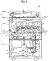
- FIG. 2 is a schematic sectional view of the image forming apparatus 1000, which in this example embodiment is a tandem-type full-color laser copier including a plurality of image carriers, also called photoconductors, provided side by side.
- image carriers also called photoconductors
- the scanner body 300 further includes an exposure glass 32, a first traveling body 33, a second traveling body 34, an image focusing lens 35, and/or a read sensor 36.
- the image forming apparatus body 2 further includes a printer 100 and/or a feeding device 200.
- the printer 100 includes an image forming unit 20 and/or an output tray 57.
- the image forming unit 20 includes process cartridges 18Y, 18M, 18C, and 18K, an optical writing unit 21, an intermediate transfer unit 17, a secondary transfer device 22, a pair of registration rollers 49, a fixing device 25, and/or development devices 4Y, 4M, 4C, and 4K.
- the process cartridges 18Y, 18M, 18C, and 18K include image carriers 1Y, 1M, 1C, and 1K, respectively.
- the intermediate transfer unit 17 includes an intermediate transfer belt 110, a belt cleaner 90, a driven roller 14, a driving roller 15, a secondary transfer backup roller 16, and/or primary transfer bias rollers 62Y, 62M, 62C, and 62K.
- the secondary transfer device 22 includes tension rollers 23 and/or a conveyance belt 24.
- the fixing device 25 includes a fixing belt 26 and/or a pressing roller 27.
- the feeding device 200 includes a paper bank 43, feed rollers 42, separation rollers 45, a feed path 46, a pair of conveyance rollers 47, a bypass tray 51, a bypass feed roller 50, a separation roller 52, and/or a bypass feed path 53.
- the paper bank 43 includes multiple paper trays 44.
- the printer 100 is provided on the feeding device 200.
- the scanner body 300 is provided on the printer 100.
- the automatic document feeder 400 is provided on the scanner 300, and is capable of rotating.
- the process cartridges 18Y, 18M, 18C, and 18K form yellow, magenta, cyan, and black toner images, respectively.
- the optical writing unit 21 includes a light source, a polygon mirror, an f- ⁇ lens, and/or a reflecting mirror, and directs a laser beam onto respective surfaces of the image carriers 1Y, 1M, 1C, and 1K based on image data, so that an electrical potential of an irradiation portion (exposure portion) of the respective surfaces of the image carriers 1Y, 1M, 1C, and 1K is attenuated. As a result, an electrostatic latent image is formed on the respective surfaces of the image carriers 1Y, 1M, 1C, and 1K.
- the development devices 4Y, 4M, 4C, and 4K develop the electrostatic latent images formed on the respective surfaces of the image carriers 1Y, 1M, 1C, and 1K into visible toner images.
- the toner images formed on the image carriers 1Y, 1M, 1C, and 1K are primarily transferred to the intermediate transfer belt 110, respectively. Thereafter, a cleaning device removes toner particles remaining on the respective surfaces of the image carriers 1Y, 1M, 1C, and 1K. After being processed by a lubricant application device, the respective surfaces of the image carriers 1Y, 1M, 1C, and 1K are discharged by a discharger, and uniformly supplied with an electrical charge by a charger, returning to an initial condition.
- the intermediate transfer belt 110 is wrapped around the driven roller 14, the driving roller 15, the secondary transfer backup roller 16, and the primary transfer bias rollers 62Y, 62M, 62C, and 62K, and moves in a direction A due to rotation of the driving roller 15 driven by a motor.
- the primary transfer bias rollers 62Y, 62M, 62C, and 62K are provided on an inner circumferential surface of the intermediate transfer belt 110, and supplied with a primary transfer bias from a power source.
- the primary transfer bias rollers 62Y, 62M, 62C, and 62K press the inner circumferential surface of the intermediate transfer belt 110 against the image carriers 1Y, 1M, 1C, and 1K, forming a primary transfer nip between the image carriers 1Y, 1M, 1C, and 1K and the primary transfer bias rollers 62Y, 62M, 62C, and 62K, respectively.
- a primary transfer electrical field is formed in the primary transfer nip formed between the image carriers 1Y, 1M, 1C, and 1K and the primary transfer bias rollers 62Y, 62M, 62C, and 62K, respectively.
- the yellow toner image formed on the image carrier 1Y is primarily transferred onto the intermediate transfer belt 110 by the primary transfer electrical field and a nip pressure.
- the magenta, cyan, and black toner images formed on the image carriers 1M, 1C, and 1K are sequentially transferred and superimposed onto the intermediate transfer belt 110 bearing the yellow toner image, thereby forming a four-color toner image on the intermediate transfer belt 110.
- the four-color toner image formed on the intermediate transfer belt 110 is transferred to a sheet at a secondary transfer nip, described later.
- the belt cleaner 90 removes residual toner remaining on a surface of the intermediate transfer belt 110 sandwiched between the belt cleaner 90 and the driven roller 14.
- the secondary transfer device 22 is provided in a lower portion of the intermediate transfer unit 17.
- the conveyance belt 24 is wrapped around two tension rollers 23, and moves due to rotation of at least one of the tension rollers 23.
- the intermediate transfer belt 110 and the conveyance belt 24 are sandwiched between the tension roller 23 provided to the right in FIG. 2 and the secondary transfer backup roller 16, thereby forming the secondary transfer nip between the intermediate transfer belt 110 and the conveyance belt 24 contacting each other. Since the tension roller 23 is supplied with a secondary transfer bias having a polarity opposite to that of toner particles, a secondary transfer electrical field is formed at the secondary transfer nip to cause the four-color toner image formed on the intermediate transfer belt 110 to electrostatically transfer to the tension roller 23.
- the pair of registration rollers 49 feeds a sheet to the secondary transfer nip, thereby transferring the four-color toner image to the sheet by the secondary transfer electrical field and a nip pressure.
- a charger charging a sheet in a non-contact manner may be provided instead of such a secondary transfer method of supplying the tension roller 23 with the secondary transfer bias.
- the feeding device 200 is provided in a lower portion of the image forming apparatus body 2.
- the plurality of paper trays 44 is provided in the feeding device 200, vertically separated from each other and capable of storing a plurality of sheets in a stack.
- the feed roller 42 contacts an uppermost sheet stacked in the paper tray 44. As the feed roller 42 rotates, the uppermost sheet is conveyed to the feed path 46.
- the pair of registration rollers 49 is provided in the vicinity of an end portion of the feed path 46.
- the sheet fed from the paper tray 44 is conveyed through the feed path 46 to the pair of registration rollers 49 via the plurality of pairs of conveyance rollers 47, and sandwiched between the pair of registration rollers 49.
- the four-color toner image formed on the intermediate transfer belt 110 moves to the secondary transfer nip formed between the intermediate transfer belt 110 and the conveyance belt 24 as rotation of the intermediate transfer belt 110.
- the pair of registration rollers 49 feeds the sheet at a proper time when the four-color toner image formed on the intermediate transfer belt 110 is transferred onto the sheet at the secondary transfer nip. As a result, a full color toner image is formed on the sheet.
- the sheet bearing the full color toner image moves as rotation of the conveyance belt 24 and is conveyed to the fixing device 25.
- the fixing device 25 uses a belt fixing method.
- the fixing belt 26 is wrapped around two rollers, and rotates, forming a belt unit.
- the pressing roller 27 presses the fixing belt 26.
- the fixing belt 26 and the pressing roller 27 contact each other, forming a fixing nip therebetween to receive the sheet conveyed from the conveyance belt 24.
- One of the rollers included in the belt unit, pressed against the pressing roller 27, includes a heat source provided inside the roller to heat the fixing belt 26.
- the heated fixing belt 26 heats the sheet received by the fixing nip formed between the fixing belt 26 and the pressing roller 27. Due to heating and a nip pressure, the full color toner image is fixed to the sheet.
- the sheet is discharged to the output tray 57 protruding from a side plate of the image forming apparatus body 2.
- the sheet is again conveyed to the secondary transfer nip, so as to form another toner image on the other side of the sheet.
- the exposure glass 32 serving as an exposure surface, used as a contact plate may be not glass but a plastic sheet, for example, acrylic and the like. That is, the exposure glass 32 may be of any transparent material.
- the user presses a copy key to order start of reading of the original document by the scanner body 300.
- the automatic document feeder 400 automatically moves the original document to the exposure glass 32.
- a light source provided in the first traveling body 33 emits light. After being reflected from an original document surface, the light is then reflected by a mirror, passes through the image focusing lens 35, and strikes the read sensor 36, which constructs image information based on the light.
- each device included in each of the process cartridges 18Y, 18M, 18C, and 18K, the intermediate transfer unit 17, the secondary transfer device 22, and the fixing device 25 start operation, respectively.
- the optical writing unit 21 Based on the image information constructed by the read sensor 36, the optical writing unit 21 performs writing to form yellow, magenta, cyan, and black toner images on the respective surfaces of the image carriers 1Y, 1M, 1C, and 1K.
- the respective toner images are transferred and superimposed onto the intermediate transfer belt 110, forming a four-color toner image.
- the feeding device 200 starts feeding a sheet.
- One of the plurality of feed rollers 42 selectively rotates to feed a sheet from one of the plurality of paper tray 44 provided in the paper bank 43.
- the separation roller 45 separates one sheet from another to feed each sheet to the feed path 46
- the pair of conveyance rollers 47 conveys the sheet toward the secondary transfer nip.
- the bypass tray 51 feeds a sheet.
- the bypass feed roller 50 selectively rotates to feed the sheet to the inside of the image forming apparatus 1000.
- the separation roller 52 separates one sheet from another, so that each sheet is conveyed to the bypass feed path 53 of the printer 100.
- the image carriers 1Y, 1M, 1C, and 1K contact an upper surface of the intermediate transfer belt 110 stretched substantially in a horizontal direction.
- a mechanism not shown, causes the intermediate transfer belt 110 to incline to the left in FIG. 2 to separate the upper surface of the intermediate transfer belt 110 from the image carriers 1Y, 1M, and 1C.
- the image carrier 1K rotates and forms a black toner image.
- the development devices 4Y, 4M, 4C, and 4K also stop operation, respectively.
- the image forming apparatus 1000 includes a controller including a CPU and the like controlling each device included in the image forming apparatus 1000.
- the control panel 28 depicted in FIG. 1 includes a liquid crystal display, various keys, and the like. The user can choose either a single-sided printing mode or a duplex printing mode by input operation using the control panel 28 to transmit a command to the controller.
- FIG. 3 is a schematic side view of the image forming apparatus 1000.
- the automatic document feeder 400 further includes a catch portion T.
- the catch portion T includes a sloped portion TA.
- the catch portion T is provided on the front of the automatic document feeder 400 and extends obliquely upwards to the proximal end of the automatic document feeder 400 to protrude from the front surface of the scanner body 300. As a result, the user can easily grasp the catch portion T to raise the automatic document feeder 400. Due to the above, the image forming apparatus 1000 does not increase in depth. Moreover, the user can easily access and remove the sheet discharged to the output tray 2A provided on the upper surface of the image forming apparatus body 2.
- the sloped portion TA of the catch portion T inclines downwards from the proximal end to the distal end of the rotatable scanner 3. Although the sloped surface TA is generally a flat surface as illustrated in FIG.
- the sloped portion TA may be curved, stepped, or the like.
- the catch portion T may have any shape, when it extends obliquely upwards to the proximal end of the automatic document feeder 400 to protrude from the front surface of the scanner body 300.
- FIG. 4 is a side view of the image forming apparatus 1000. Since the rotatable scanner 3 is provided on a distal end of the upper surface of the image forming apparatus body 2, an empty area is formed above a front surface of the image forming apparatus body 2 to enable the user to easily remove the sheet discharged to the output tray 2A. That is, the rotatable scanner 3 is provided in substantially a rearward portion of the image forming apparatus 1000 in order to facilitate removal of the discharged sheet. In addition, a rear surface of the rotatable scanner 3 is substantially flush with a rear surface of the image forming apparatus body 2. This is because protrusion of the rotatable scanner 3 from the rear surface of the image forming apparatus body 2 causes an increased depth of the image forming apparatus 1000 and requires a larger installation space.
- the automatic document feeder 400 is attached to a distal end of the scanner body 300, and is rotatable about an axis of rotation in directions indicated by the double-headed arrow B. That is, the document holder includes a hinged side and a free side opposite the hinged side. A front upper edge of the scanner body 3 is chamfered to form the sloped surface 300A.
- the concave portion 400A is provided on a lower front surface of the automatic document feeder 400 to form a catch portion. Thus, when the user puts their fingers in the concave portion 400A and lifts the automatic document feeder 400, the automatic document feeder 400 rotates upwards to expose the exposure glass 32, serving as an exposure surface, depicted in FIG. 2 .
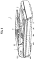
- FIG. 5 is a schematic perspective view of the rotatable scanner 3.
- FIG. 6 is a partial sectional view of the rotatable scanner 3.
- the scanner body 300 further includes a wall 300B.
- the concave portion 400A includes a wall 400A1.
- the scanner body 300 has a substantially rectangular parallelepiped shape and a small thickness in response to growing demand for compact and lightweight scanners.
- the front of the automatic document feeder 400 is beak-shaped.
- the upper edge of the scanner body 300 provided on the opening and closing side of the automatic document feeder 400 is chamfered to form the sloped surface 300A.
- the sloped surface 300A has a planar surface. More specifically, the planar sloped surface 300A inclines downwards to the proximal end of the scanner body 300.
- the sloped surface 300A may include any shape easy to lift up the automatic document feeder 400, for example, a round shape.
- the concave portion 400A is provided in the catch portion T of the automatic document feeder 400.
- the sloped surface 300A and the concave portion 400A together form a space S for accommodating the user's fingers, extending in a longitudinal direction of the rotatable scanner 3.
- the concave portion 400A may include fine surface irregularities to enable the user to easily distinguish the concave portion 400A from other portions by touch. In addition, such irregularities provide a better grip for the user's hands on the automatic document feeder 400 when the user lifts the automatic document feeder 400.
- the wall 300B is vertically provided at both ends of the sloped surface 300A in the longitudinal direction of the scanner body 300 to form the space S.
- the wall 400A1 is provided at both ends of the concave portion 400A in the longitudinal direction of the scanner body 300. Provisions of the wall 300B and the wall 400A1 enable the user to easily ascertain a position of the space S just by touch, thereby making the rotatable scanner 3 convenient for visually-impaired users. Alternatively, after visually confirming the position of the space S, the user inserts their fingers into the space S, moves their hands to the wall 400A1 to confirm a position of an end of the space S, and positions their hands so as to lift easily the automatic document feeder 400.
- the rotatable scanner 3 is operable for a variety of tasks.
- the rotatable scanner 3 is useful for such operations as copying, faxing, and scanning involving frequent opening and closing of a document holder, that is, the automatic document feeder 400.
- a conventional scanner is less accessible to an occupant of a wheelchair than to a physically unimpaired person.
- such physically impaired person can position their hands appropriately on the rotatable scanner 3 by merely feeling the automatic document feeder 400 and can easily lift up the automatic document feeder 400 without using very much physical force.
- the image forming apparatus 1000 includes the automatic document feeder 400, serving as a document holder, in which the catch portion T depicted in FIG. 6 is provided on the front surface of the automatic document feeder 400 and extends obliquely upwards to the proximal end of the automatic document feeder 400 to protrude from the front surface of the scanner body 300. Therefore, the image forming apparatus 1000 does not increase in depth. As a result, the user can easily remove the sheet discharged to the output tray 2A depicted in FIG. 4 provided on the upper surface of the image forming apparatus body 2 and easily lifts the automatic document feeder 400.
- the image forming apparatus 1000 includes the rotatable scanner 3 including the scanner body 3 in which the front upper edge of the scanner body 3 is chamfered to form the sloped surface 300A depicted in FIG. 6 . Therefore, even when a catch portion, that is, the concave portion 400A depicted in FIG. 6 , is not large enough to accommodate the user's fingers, the user can easily lift the automatic document feeder 400 with their fingers.
- the sloped surface 300A is largely chamfered, the user can easily insert their fingers into the space S depicted in FIG. 6 , even when the concave portion 400A is not provided in the automatic document feeder 400. Accordingly, even though the automatic document feeder 400 decreases in thickness, the user can easily put their fingers in the space S to lift up the automatic document feeder 400.
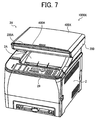
- FIG. 7 is a schematic perspective view of the image forming apparatus 1000A.
- the image forming apparatus 1000A includes the image forming apparatus body 2 and/or a rotatable scanner 3X.
- the rotatable scanner 3X includes the scanner body 300 and/or a press plate 400X.
- the press plate 400X includes the concave portion 400A.
- the scanner body 300 includes the sloped surface 300A.
- the press plate 400X serving as a document holder, is thinner than the automatic document feeder 400 depicted in FIG. 1 and has a different configuration from that of the automatic document feeder 400.
- FIG. 8 is a schematic perspective view of the rotatable scanner 3X.
- the press plate 400X further includes the catch portion T and/or a mark 400B.
- the front upper edge of the scanner body 300 is chamfered to form the sloped surface 300A having a planar surface.
- the catch portion T is provided on a front of the press plate 400X, and includes the concave portion 400A used for catching the user's hands.
- the sloped surface 300A and the concave portion 400A form the space S, depicted in FIG. 6 , extending in a longitudinal direction of the scanner body 3.
- the rotatable scanner 3X has the same effect as that of the rotatable scanner 3 depicted in FIG. 1 . Since the press plate 400X is thin, the concave portion 400A does not provide a sufficient space for insertion of the user's fingers. However, since the sloped surface 300A is provided to form the space S, the user can easily insert their fingers into the space S to lift the press plate 400X. In addition, since the press plate 400X curves to the center in a width direction thereof, the user can easily insert their fingers into a center portion of the space S.
- the mark 400B is provided in the center of an upper surface of the press plate 400X in the width direction thereof, along one side thereof, to enable the user to visually grasp the center position of the catch portion T. Alternatively, a visually-impaired user can easily ascertain the center position of the space S merely by feeling the press plate 400X with their fingers.
Landscapes
- Engineering & Computer Science (AREA)
- Multimedia (AREA)
- Signal Processing (AREA)
- Electrophotography Configuration And Component (AREA)
- Facsimiles In General (AREA)
- Holders For Sensitive Materials And Originals (AREA)
Claims (8)
- Scanner rotatif (3), comprenant :un corps de scanner (300) comprenant une surface d'exposition (32) sur laquelle est placé un document ; etun support du document (400), monté de manière rotative sur le corps du scanner et agencé au-dessus du corps du scanner pour recouvrir un document placé sur la surface d'exposition du corps du scanner, comprenant un côté articulé et un côté libre opposé au côté articulé ;le corps du scanner (300) étant caractérisé en ce qu'il comprend un bord supérieur avant chanfreiné (300A), agencé sur un côté correspondant au côté libre du support du document (400), dans lequel le support du document (400) comprend une partie d'encliquetage (T), agencée sur le côté libre du support du document, s'étendant obliquement vers le haut afin de déborder, dans la direction allant à l'écart du côté articulé sur le support du document (400), d'une surface avant du corps du scanner (300).
- Scanner selon la revendication 1,
dans lequel le corps du scanner (300) comprend une paroi (300B) agencée de manière verticale au niveau des deux extrémités du bord chanfreiné sur le corps du scanner, dans une direction longitudinale du corps du scanner. - Scanner selon la revendication 1,
dans lequel la partie d'encliquetage (T) comprend une surface inclinée (TA), inclinée vers le bas, d'une extrémité proximale vers une extrémité distale du scanner rotatif (3). - Scanner selon la revendication 3,
dans lequel la surface inclinée (TA) comprend une partie concave (400A) pour recevoir les doigts d'un utilisateur. - Appareil de formation d'images (1000), comprenant
un scanner rotatif (3) selon la revendication 1. - Appareil de formation d'images selon la revendication 5,
dans lequel le corps du scanner (300) comprend une paroi (300B), agencée de manière verticale au niveau des deux extrémités du bord chanfreiné du corps du scanner, dans une direction longitudinale du corps du scanner. - Appareil de formation d'images selon la revendication 5,
dans lequel la partie d'encliquetage (T) comprend une surface inclinée (TA), inclinée vers le bas, d'une extrémité proximale vers une extrémité distale du scanner rotatif (3). - Appareil de formation d'images selon la revendication 7,
dans lequel la surface inclinée (TA) comprend une partie concave (400A) pour recevoir les doigts d'un utilisateur.
Applications Claiming Priority (2)
| Application Number | Priority Date | Filing Date | Title |
|---|---|---|---|
| JP2008029798A JP4990176B2 (ja) | 2008-02-08 | 2008-02-08 | 圧板開閉式スキャナ、画像形成装置 |
| JP2008031065A JP5122998B2 (ja) | 2008-02-12 | 2008-02-12 | 画像形成装置 |
Publications (3)
| Publication Number | Publication Date |
|---|---|
| EP2107781A2 EP2107781A2 (fr) | 2009-10-07 |
| EP2107781A3 EP2107781A3 (fr) | 2009-11-11 |
| EP2107781B1 true EP2107781B1 (fr) | 2016-06-22 |
Family
ID=40938641
Family Applications (1)
| Application Number | Title | Priority Date | Filing Date |
|---|---|---|---|
| EP09250286.3A Active EP2107781B1 (fr) | 2008-02-08 | 2009-02-04 | Dispositif de balayage rotatif et appareil de formation d'images |
Country Status (2)
| Country | Link |
|---|---|
| US (2) | US8526068B2 (fr) |
| EP (1) | EP2107781B1 (fr) |
Families Citing this family (8)
| Publication number | Priority date | Publication date | Assignee | Title |
|---|---|---|---|---|
| USD618276S1 (en) * | 2007-09-28 | 2010-06-22 | Ricoh Company, Ltd. | Scanner for laser printer |
| JP5641218B2 (ja) | 2010-10-25 | 2014-12-17 | 富士ゼロックス株式会社 | 原稿読取装置及び画像形成装置 |
| JP5533824B2 (ja) | 2011-09-09 | 2014-06-25 | ブラザー工業株式会社 | 複合機 |
| US9049326B2 (en) * | 2011-09-09 | 2015-06-02 | Brother Kogyo Kabushiki Kaisha | Multifunction device with scanner unit offset from recording sheet tray |
| JP6067994B2 (ja) * | 2012-04-16 | 2017-01-25 | シャープ株式会社 | 画像形成装置 |
| JP5942614B2 (ja) | 2012-06-05 | 2016-06-29 | 株式会社リコー | 情報処理装置、システム及びプログラム |
| US10630862B2 (en) | 2016-09-08 | 2020-04-21 | Hewlett-Packard Development Company, L.P. | Transparent platen with chamfered egress edge |
| JP2023150151A (ja) * | 2022-03-31 | 2023-10-16 | 京セラドキュメントソリューションズ株式会社 | 画像形成装置 |
Family Cites Families (26)
| Publication number | Priority date | Publication date | Assignee | Title |
|---|---|---|---|---|
| DE3730198A1 (de) | 1987-09-09 | 1989-03-23 | Heraeus Gmbh W C | Verfahren zur herstellung eines laenglichen transparenten koerpers aus kunststoff und deren verwendung |
| JP3595026B2 (ja) | 1995-06-12 | 2004-12-02 | 株式会社リコー | 画像形成装置 |
| JPH09142716A (ja) | 1995-11-21 | 1997-06-03 | Ricoh Co Ltd | 画像形成装置 |
| JPH10208107A (ja) | 1997-01-28 | 1998-08-07 | Glory Ltd | 硬貨入金装置および循環式硬貨入出金機 |
| JP3720602B2 (ja) * | 1998-10-21 | 2005-11-30 | 株式会社リコー | 画像形成装置 |
| JP2000132010A (ja) * | 1998-10-21 | 2000-05-12 | Ricoh Co Ltd | 画像形成装置 |
| JP2000275923A (ja) * | 1999-01-22 | 2000-10-06 | Ricoh Co Ltd | 画像形成装置 |
| JP4447764B2 (ja) * | 2000-11-13 | 2010-04-07 | キヤノン株式会社 | シート給送装置及びこれを備えた画像読取装置 |
| JP3356172B2 (ja) | 2001-06-11 | 2002-12-09 | 富士ゼロックス株式会社 | 画像形成装置 |
| CN2567919Y (zh) | 2002-07-26 | 2003-08-20 | 旭丽股份有限公司 | 一种办公设备的控制面板结构 |
| JP2004088350A (ja) | 2002-08-26 | 2004-03-18 | Canon Inc | 画像読取記録装置 |
| US6965392B2 (en) * | 2002-08-26 | 2005-11-15 | Canon Kabushiki Kaisha | Image reading and recording apparatus |
| JP4188075B2 (ja) | 2002-12-27 | 2008-11-26 | ブラザー工業株式会社 | 画像形成装置 |
| JP2004138683A (ja) | 2002-10-15 | 2004-05-13 | Canon Inc | 画像形成装置 |
| US7016629B2 (en) * | 2003-04-17 | 2006-03-21 | Ricoh Company, Ltd. | Image forming apparatus with discharging unit of increased capacity |
| JP4397632B2 (ja) | 2003-06-30 | 2010-01-13 | ブラザー工業株式会社 | 原稿搬送装置 |
| JP2005242267A (ja) | 2004-02-27 | 2005-09-08 | Canon Inc | 画像形成装置 |
| JP2006133249A (ja) * | 2004-11-02 | 2006-05-25 | Ricoh Co Ltd | 表示体装着構造、これを備えた機器、画像形成装置 |
| JP4480553B2 (ja) | 2004-11-19 | 2010-06-16 | 株式会社リコー | 画像形成装置 |
| JP2006145804A (ja) * | 2004-11-19 | 2006-06-08 | Ricoh Co Ltd | 画像形成装置 |
| WO2007023959A1 (fr) * | 2005-08-26 | 2007-03-01 | Matsushita Electric Industrial Co., Ltd. | Dispositif de saisie d’image et dispositif de formation d’image utilisant celui-ci |
| JP4790354B2 (ja) | 2005-09-12 | 2011-10-12 | 株式会社リコー | 画像形成装置 |
| JP2008009377A (ja) | 2006-05-30 | 2008-01-17 | Ricoh Co Ltd | 画像形成装置 |
| JP4750627B2 (ja) | 2006-06-09 | 2011-08-17 | キヤノン株式会社 | 画像読取記録装置 |
| JP2008029798A (ja) | 2006-07-05 | 2008-02-14 | Oita Univ | 胸部x線像とその左右反転像を用いるサブトラクション方法 |
| JP2008031065A (ja) | 2006-07-27 | 2008-02-14 | Seems Inc | 発毛・育毛剤 |
-
2009
- 2009-02-04 EP EP09250286.3A patent/EP2107781B1/fr active Active
- 2009-02-04 US US12/320,761 patent/US8526068B2/en not_active Expired - Fee Related
-
2013
- 2013-07-23 US US13/948,834 patent/US8736921B2/en active Active
Also Published As
| Publication number | Publication date |
|---|---|
| US20130308168A1 (en) | 2013-11-21 |
| US8526068B2 (en) | 2013-09-03 |
| US20090201559A1 (en) | 2009-08-13 |
| US8736921B2 (en) | 2014-05-27 |
| EP2107781A2 (fr) | 2009-10-07 |
| EP2107781A3 (fr) | 2009-11-11 |
Similar Documents
| Publication | Publication Date | Title |
|---|---|---|
| US8736921B2 (en) | Rotatable scanner and image forming apparatus | |
| US8561979B2 (en) | Open/close mechanism for paper tray for use in image forming apparatus | |
| EP1826626B1 (fr) | Appareils de formation d'images en couleur, formation d'images en couleur en tandem et formation d'images | |
| EP0817459B1 (fr) | Dispositif électrophotographique de formation d'images avec dispositif de lecture de documents monté de manière amovible | |
| KR101512357B1 (ko) | 시트 반송 장치, 이것을 구비한 화상 판독 장치, 및 화상 형성 장치 | |
| JP2012158422A (ja) | シート給紙装置及び画像形成装置 | |
| US9388013B2 (en) | Sheet discharging device and image forming apparatus provided with same | |
| US20120243919A1 (en) | Fixing device and image forming apparatus provided with the same | |
| CN101893830B (zh) | 图像形成装置以及转印辊偏压系统 | |
| CN101504523B (zh) | 可旋转的扫描仪和图像形成设备 | |
| CN104345601A (zh) | 供纸装置和图像形成装置 | |
| JP4493477B2 (ja) | 画像形成装置、その補充用紙表示方法及びその方法をコンピュータに実行させるためのプログラム | |
| US10530948B2 (en) | Image forming apparatus | |
| JP2022035688A (ja) | 画像形成装置 | |
| JP5376035B2 (ja) | 画像形成装置 | |
| JP2014041217A (ja) | 画像形成装置 | |
| JP5122998B2 (ja) | 画像形成装置 | |
| JP6383035B2 (ja) | 画像形成装置 | |
| JP6518495B2 (ja) | 給紙装置およびそれを備える画像形成装置 | |
| JP4214724B2 (ja) | 画像形成装置 | |
| JP2023065015A (ja) | シート搬送装置および画像形成装置 | |
| JP2014032413A (ja) | 画像形成装置 | |
| JP2006151618A (ja) | 画像形成装置 | |
| JP2018165842A (ja) | 画像形成装置 | |
| HK1005285B (en) | Electrophotographic image-forming apparatus with detachably mounted document-reading unit |
Legal Events
| Date | Code | Title | Description |
|---|---|---|---|
| PUAI | Public reference made under article 153(3) epc to a published international application that has entered the european phase |
Free format text: ORIGINAL CODE: 0009012 |
|
| 17P | Request for examination filed |
Effective date: 20090211 |
|
| AK | Designated contracting states |
Kind code of ref document: A2 Designated state(s): AT BE BG CH CY CZ DE DK EE ES FI FR GB GR HR HU IE IS IT LI LT LU LV MC MK MT NL NO PL PT RO SE SI SK TR |
|
| AX | Request for extension of the european patent |
Extension state: AL BA RS |
|
| PUAL | Search report despatched |
Free format text: ORIGINAL CODE: 0009013 |
|
| AK | Designated contracting states |
Kind code of ref document: A3 Designated state(s): AT BE BG CH CY CZ DE DK EE ES FI FR GB GR HR HU IE IS IT LI LT LU LV MC MK MT NL NO PL PT RO SE SI SK TR |
|
| AX | Request for extension of the european patent |
Extension state: AL BA RS |
|
| 17Q | First examination report despatched |
Effective date: 20100216 |
|
| AKX | Designation fees paid |
Designated state(s): DE FR GB |
|
| GRAP | Despatch of communication of intention to grant a patent |
Free format text: ORIGINAL CODE: EPIDOSNIGR1 |
|
| INTG | Intention to grant announced |
Effective date: 20160104 |
|
| INTG | Intention to grant announced |
Effective date: 20160107 |
|
| GRAS | Grant fee paid |
Free format text: ORIGINAL CODE: EPIDOSNIGR3 |
|
| GRAA | (expected) grant |
Free format text: ORIGINAL CODE: 0009210 |
|
| AK | Designated contracting states |
Kind code of ref document: B1 Designated state(s): DE FR GB |
|
| REG | Reference to a national code |
Ref country code: GB Ref legal event code: FG4D |
|
| REG | Reference to a national code |
Ref country code: DE Ref legal event code: R096 Ref document number: 602009039306 Country of ref document: DE |
|
| REG | Reference to a national code |
Ref country code: FR Ref legal event code: PLFP Year of fee payment: 9 |
|
| REG | Reference to a national code |
Ref country code: DE Ref legal event code: R097 Ref document number: 602009039306 Country of ref document: DE |
|
| PLBE | No opposition filed within time limit |
Free format text: ORIGINAL CODE: 0009261 |
|
| STAA | Information on the status of an ep patent application or granted ep patent |
Free format text: STATUS: NO OPPOSITION FILED WITHIN TIME LIMIT |
|
| 26N | No opposition filed |
Effective date: 20170323 |
|
| REG | Reference to a national code |
Ref country code: FR Ref legal event code: PLFP Year of fee payment: 10 |
|
| P01 | Opt-out of the competence of the unified patent court (upc) registered |
Effective date: 20230522 |
|
| PGFP | Annual fee paid to national office [announced via postgrant information from national office to epo] |
Ref country code: DE Payment date: 20250218 Year of fee payment: 17 |
|
| PGFP | Annual fee paid to national office [announced via postgrant information from national office to epo] |
Ref country code: FR Payment date: 20250221 Year of fee payment: 17 |
|
| PGFP | Annual fee paid to national office [announced via postgrant information from national office to epo] |
Ref country code: GB Payment date: 20250219 Year of fee payment: 17 |