EP2107799B1 - Caméra infrarouge et méthode de traîtement des informations dans les images - Google Patents
Caméra infrarouge et méthode de traîtement des informations dans les images Download PDFInfo
- Publication number
- EP2107799B1 EP2107799B1 EP09155228.1A EP09155228A EP2107799B1 EP 2107799 B1 EP2107799 B1 EP 2107799B1 EP 09155228 A EP09155228 A EP 09155228A EP 2107799 B1 EP2107799 B1 EP 2107799B1
- Authority
- EP
- European Patent Office
- Prior art keywords
- image
- visual
- camera
- distance
- visual image
- Prior art date
- Legal status (The legal status is an assumption and is not a legal conclusion. Google has not performed a legal analysis and makes no representation as to the accuracy of the status listed.)
- Active
Links
Images


Classifications
-
- H—ELECTRICITY
- H04—ELECTRIC COMMUNICATION TECHNIQUE
- H04N—PICTORIAL COMMUNICATION, e.g. TELEVISION
- H04N13/00—Stereoscopic video systems; Multi-view video systems; Details thereof
- H04N13/20—Image signal generators
- H04N13/204—Image signal generators using stereoscopic image cameras
- H04N13/25—Image signal generators using stereoscopic image cameras using two or more image sensors with different characteristics other than in their location or field of view, e.g. having different resolutions or colour pickup characteristics; using image signals from one sensor to control the characteristics of another sensor
-
- H—ELECTRICITY
- H04—ELECTRIC COMMUNICATION TECHNIQUE
- H04N—PICTORIAL COMMUNICATION, e.g. TELEVISION
- H04N23/00—Cameras or camera modules comprising electronic image sensors; Control thereof
- H04N23/10—Cameras or camera modules comprising electronic image sensors; Control thereof for generating image signals from different wavelengths
- H04N23/11—Cameras or camera modules comprising electronic image sensors; Control thereof for generating image signals from different wavelengths for generating image signals from visible and infrared light wavelengths
-
- H—ELECTRICITY
- H04—ELECTRIC COMMUNICATION TECHNIQUE
- H04N—PICTORIAL COMMUNICATION, e.g. TELEVISION
- H04N23/00—Cameras or camera modules comprising electronic image sensors; Control thereof
- H04N23/20—Cameras or camera modules comprising electronic image sensors; Control thereof for generating image signals from infrared radiation only
Definitions
- the present invention relates to detection of laser light in an infrared image captured by an IR camera.
- an essential construction detail that is only visible in the visual spectrum of the radiation, as well as a heat leakage which is only visible in the infrared spectrum of the radiation, could be relevant information during a maintenance assignment.
- IR cameras are equipped with a laser pointer, but the reflected laser light is detected only in the visual spectrum of the radiation and not in the infrared spectrum of the radiation. Hence, the laser point generated on the object by the laser pointer will be visible in the visual image but not in the IR image. It is therefore desirable to determine accurately the positions of hot and cold areas shown in the IR image by detecting reflected laser light. Moreover, current laser devices operating in the infrared spectrum of the radiation have too high energy and may also be harmful to objects or people in the vicinity.
- Document 2006/289772 discloses an IR camera with a visible light camera module and an infrared camera module and a method for displaying IR and/or visible light images.
- the camera may also comprise a laser pointer to help identify locations of points-of-interest in the images.
- the camera is calibrated to identify the location of the laser spot in the infrared image using parallax calibration data as a function of the infrared focus distance, i.e. the focus position of the infrared lens.
- the invention relates to a method for processing information in images comprising the steps of receiving emitted and reflected radiation from an object, generating a visual image and an infrared image based on the received radiation and generating a laser spot on the object by means of a laser pointing device.
- the method is further defined according to the steps in claims 1-7.
- the invention also relates to an IR camera for processing information in images comprising a first imaging part for capturing IR image data of an object, a second imaging part for capturing visible light data of the object, a laser pointer for providing a laser spot on the object, and a processor for generating an IR image based on the IR image data and a visual image based on the visible light data; a memory comprising means for storing the at least two different images and determined at least one calibration and fusion coefficient;
- the IR camera is further defined according to the features of claims 8-14.
- FIG. 1 shows a schematic view of an IR camera 10 according to an embodiment of the invention.
- the IR camera 10 comprises an assembly 12 holding three optical systems which typically comprise one or more lenses and control devices for adjusting the lenses to capture the incoming radiation from an object.
- the assembly 12 comprises a visual optical system 14 which comprises a visual sensor array 16 for the visual spectrum of the radiation, and an infrared optical system 18 comprising an infrared sensor array 20 for the infrared spectrum of the radiation.
- the final optical system comprised in the assembly 12 generates a laser beam and this system is known as a laser point system 22.
- the emitted laser beam is reflected on the object and is typically visible by the naked eye as a red spot (e.g. semiconductor AIGaINP Diode Laser ImW/635 nm).
- the reflected light of the laser beam, as well as other emitted radiation from the object, is captured by the sensor arrays 16, 20 and turned into signals which are processed by a processing device 13 to produce both a visual image and an infrared image.
- the processing device 13 may also produce of the visual and infrared images typically a fused or blended image.
- Other possible data that may be displayed to a user of the IR camera may also be processed.
- the IR camera 10 comprises a memory storage 15 for storing the data registered or processed by the IR camera 10 as well as a plurality of control devices 19 (e.g. a display, thumb-joystick and record/push-buttons) and at least one interface medium 21 (e.g. wired or wireless connections, IRDA, Bluetooth, USB, Fire-Wire, etc).
- the reflected light of the laser beam may be detected in the visual image by its picture elements, i.e. pixels.
- the picture elements may, for example be CCDs (charge-coupled devices). This is not the case in the infrared sensor array 20 .
- Figure 2 illustrates the field of view of the visual optical system 14 of the IR camera 10 in fig. 1 , represented as an angle ⁇ and the field of view of the infrared optical system 18 of the IR camera 10 in fig. 1 , represented as an angle ⁇ .
- the optical axes of both the visual optical system 14 and the infrared optical system 18 are shown as dashed lines OA1 and OA2, respectively.
- the laser beam is represented as a solid line L. As can be seen in fig. 2 the laser beam L is emitted at a distance from the optical axis OA1 of the visual optical system 14 and with a certain angle ⁇ relative to the optical axis.
- a dotted line parallel to the optical axes OA1, OA2 is provided to illustrate the angle ⁇ .
- the distance between the point where the laser beam hits the object i.e. a laser point LP
- a fixed point FP in the field of view varies with the distance z between the IR camera and the object.
- the fixed point FP in the field of view is typically indicated by the bisector of the angle ⁇ , i.e. where the optical axis of the visual optical system 14 hits the object.
- the distance between the laser point LP and the fixed point FP is a first object distance d1.
- the distance between the laser point LP and the fixed point FP is a second object distance d2.
- the laser point LP will appear in different positions relative to the distinct field of views of each optical system.
- c1 and c2 are constants to be determined
- d is the distance between the laser point LP and the fixed point FP in the visual image
- z is the distance between the IR camera and the object.
- the constant c1 is dependent on the distance between the laser point system 22 and the visual optical system 14 and the constant c2 is dependent on the angle ⁇ between their optical axes.
- the distance d between the laser point LP and the fixed point FP in the visual image can be used to determine the distance z between the IR camera and the imaged object during normal operation.
- This distance z will be the focusing distance if the laser point system 22 is pointing at the object that should be in focus. Hence, this information can be used for exact focusing of the IR camera.
- equations (1) and (2) above are calculated separately for the x axis and the y axis of the visual image, that is, for the displacement in the horizontal and vertical direction, respectively.
- the displacement d1, d2 of the laser point LP in the visual image as a function of the distance from the IR camera to the object can be determined empirically for example during calibration of the IR camera 10, in the following way as illustrated in Figure 3 :
- the positions of the laser point may also be used to estimate an equation or a curve for the displacement as a function of the distance to the object.
- This equation, or curve is stored in a memory in the IR camera, for example, the memory storage 15, and can be used to determine the displacement needed of the laser point in the IR image in dependence of the distance z to the object as will be discussed in connection with Figures 4 and 5 .
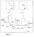
- Fig. 4 shows a calibration station 24 where the calibration coefficients needed to perform fusion between the IR image and the visual image also are determined. This is typically done for every individual produced infrared camera 10 at the calibration station 24. How to determine fusion parameters is known in the art, but will be briefly discussed in the following.
- the infrared camera 10 is rigged and aligned towards a grid screen 26 (which background color is white), where the distance z between the infrared camera 10 and the grid screen 26 is known. The distance can also be regulated.
- At least one of the black painted grid points also comprises at least one fixed point which is heated (i.e. a temperature fixed point TFP).
- the laser point LP is reflected against the screen and detected by the (two-dimensional) visual sensor array 16 of the IR camera 10 in fig. 1 , which will sense at least two pixel coordinates representing the laser point LP.
- the at least one temperature fixed point TFP preferably in the center of the screen, will be detected by both the pixel coordinates in the two dimensional visual sensor array 16 of the IR camera 10 in fig. 1 since it is painted black, and the infrared sensor array 20 of the IR camera 10 in fig. 1 , since it is heated.
- a first visual image V and a first infrared image IR is taken at a known distance z1.
- the laser point LP will be represented by the coordinates (tx VLP , ty VLP ) in the visual image.
- the at least one temperature fixed point TFP will be represented by the coordinates (tx VTFP , ty VTFP ) and (tx irTFP , ty irTFP ) in the first visual and infrared image, respectively.
- the procedure is repeated at another known distance z2 where a second visual image V' and a second infrared image IR' are taken, which will give a laser point LP' with coordinates (tx VLP' , ty VLP' ) in the visual image.
- the at least one temperature fixed point TFP' will be represented by the coordinates (tx VTFP' , ty VTFP' ) and (tx irTFP' , ty irTFP' ) in the second visual and infrared image, respectively.
- the fusion parameters are then used to determine the relative displacement of the visual image and the IR image in the x and y direction that is needed to align the images. These parameters can also be used to determine the displacement of the laser point in the IR image based on its position in the visual image.
- Figure 5 is a flow chart of how to align the IR images and visual images after calibration, during normal use of the IR camera.
- Step S51 emit a laser beam from the laser point system 22 of the IR camera 10 towards an object to generate a reflected laser point on the object.
- Step S52 capture a visual image of the object, including the laser point, using the visual optical system 14 of the IR camera 10 .
- Step S53 determine the distance d between the laser point and a predetermined point in the image, for example, the centre of the image.
- Step S54 use the distance d determined in step S53 to determine the distance z between the IR camera 10 and the object.
- Step S55 use the distance z to determine the position of the laser point in the IR image based on the fusion parameters.
- Step S56 Present the laser point in the IR image.
- steps S53 and S54 can be omitted. Instead, equations can be developed based on equations (1) - (4) above, that will permit calculation of the position of the laser point in the IR image in step S54 directly from the position in the visual image. This means that in step S54 the corresponding infrared coordinates Tx ir and Ty ir in the infrared image, may be calculated by the processing device 13 based on the information of the position of the laser point in the visual image.
- the visual and IR images are to be fused, or blended, they must be aligned. This is well known to the skilled person but will be outlined below. Since the field of view for the visual optical system 14 is approximately twice the angle of the field of view for the infrared optical system 18 it will normally completely cover the area of the object viewed by the infrared optical system 18 . Only the visual area overlapping the infrared area is taken into account, and a large amount of the visual information is therefore deleted.
- the laser point system 22 is placed in the vicinity of the infrared optical system 18, which is advantageous. The reflected laser point will always be in the area of the object which the infrared optical system covers, and will hence always be detected by the visual optical system 14 .
- the size of a sensing element is related to the wavelength of the radiation it detects, and an infrared sensing element is typically at least three times a corresponding element for the visual wavelength. This makes the infrared sensor array 20 of a lower resolution, since it has larger sensor elements or pixels than the visual sensor array 16 , and the size of a pixel in the infrared sensor array 20 could comprise at least three pixels of the visual sensor array 16 , normally more.
- the visual information is appropriately cut and aligned with corresponding information in the infrared image in a suitable manner by the fusion parameter where both the field of view and the different array resolutions must be taken into account when aligning and scaling the images.
Landscapes
- Engineering & Computer Science (AREA)
- Multimedia (AREA)
- Signal Processing (AREA)
- Length Measuring Devices By Optical Means (AREA)
- Optical Radar Systems And Details Thereof (AREA)
Claims (14)
- Un procédé pour déterminer le déplacement relatif entre une image visuelle et une image infrarouge (IR) obtenue au moyen d'un appareil de prise de vues IR- (10), le procédé comprenant les étapes consistant à :générer un point laser sur un objet, dans lequel le point laser est généré par un système (22) à point laser ;recevoir le rayonnement émis et réfléchi par l'objet, le rayonnement reçu comprenant un rayonnement provenant du point laser ;générer une image visuelle à partir d'un capteur optique (16) et une image infrarouge à partir d'un capteur infrarouge (20), les deux images étant basées sur le rayonnement reçu :détecter des coordonnées d'image visuelle du point laser dans l'image visuelle ;déterminer la distance (d) entre les coordonnées d'image visuelle du point laser et un point prédéterminé dans l'image visuelle ;déterminer une distance (z) entre l'appareil de prise de vues IR (10) et l'objet en fonction d'une distance (d) entre les coordonnées d'image visuelle du point laser et un point prédéterminé dans l'image visuelle, etdéterminer les coordonnées d'image IR du point laser dans l'image infrarouge en fonction de la distance (z) entre l'appareil de prise de vues IR (10) et l'objet et d'au moins un paramètre de déplacement (d1 -d4) en rapport avec le déplacement entre l'image visuelle et l'image IR ;la distance (z) entre l'appareil de prise de vues IR (10) et l'objet étant déterminée sur la base d'une première constante (c1) liée à la distance entre le pointeur laser et le capteur optique, et d'une deuxième constante (c2) liée à l'angle (α) entre l'axe optique du pointeur laser et l'axe optique du capteur optique ; etdéterminer les coordonnées d'image IR du point laser dans l'image IR, en utilisant le déplacement relatif entre l'image visuelle et l'image IR, etmettre en évidence l'image du point laser dans l'image infrarouge.
- Un procédé selon la revendication 1, dans lequel ledit au moins un paramètre de déplacement (d1, d2, d3, d4) est déterminée lors de l'étalonnage de l'appareil de prise de vues IR.
- Un procédé selon l'une quelconque des revendications précédentes, dans lequel le point prédéterminé dans l'image visuelle est le centre de l'image visuelle.
- Un procédé selon l'une quelconque des revendications précédentes, dans lequel ledit au moins un paramètre de déplacement (d1-d4) est un paramètre de fusion.
- Un procédé selon l'une quelconque des revendications précédentes, comprenant en outre l'étape consistant à mettre en évidence les coordonnées d'image IR du point laser dans l'image IR.
- Un procédé selon l'une quelconque des revendications précédentes, comprenant en outre l'étape consistant à créer une image fusionnée sur la base d'au moins une partie de l'image visuelle et d'au moins une partie de l'image IR, ladite au moins une partie de l'image visuelle et ladite au moins une partie de l'image IR étant alignées en utilisant le déplacement relatif déterminé de l'image visuelle et de l'image IR dans la direction x et y.
- Un procédé selon la revendication précédente, comprenant en outre l'étape consistant à mettre en évidence les coordonnées d'image IR du point laser dans l'image fusionnée.
- Un appareil de prise de vues IR (10) pour déterminer le déplacement relatif entre une image visuelle et une image infrarouge (IR), comprenant :un système à point laser (22) pour fournir un point laser sur un objet ;un capteur IR (20) pour capturer des données d'image IR relatives l'objetun capteur optique (16) pour capturer des données de lumière visible se rapportant à l'objet ;un processeur (13) destiné à générer une image IR sur la base des données d'image IR capturées par le capteur IR (20) et une image visuelle sur la base des données de lumière visible capturées par le capteur optique (16) ;une mémoire (15) comprenant des moyens pour stocker lesdites au moins deux images différentes et un paramètre de déplacement ;le processeur (13) étant agencé pour :déterminer le déplacement relatif de l'image visuelle et l'image IR dans la direction x et y sur la base d'une distance (z) entre l'appareil de prise de vues IR (10) et l'objet, et au moins un paramètre de déplacement (d1- d4) en rapport avec le déplacement entre l'image visuelle et l'image IR,détecter des coordonnées d'image visuelle du point laser dans l'image visuelle ;déterminer la distance (d) entre les coordonnées d'image visuelle du point laser et un point prédéterminé dans l'image visuelle ;déterminer une distance (z) entre l'appareil de prise de vues IR (10) etl'objet en fonction de la distance (d) entre les coordonnées d'image visuelle du point laser et un point prédéterminé dans l'image visuelle, et
le processeur (13) étant agencé pour déterminer la distance (z) entre l'appareil de prise de vues IR et l'objet en fonction d'une première constante (c1) liée la distance entre le pointeur laser et le capteur optique et d'une deuxième constante (c2) liée à l'angle (α) entre l'axe optique du pointeur laser et l'axe optique du capteur optique ; et
le processeur (13) étant en outre agencé pour déterminer et mettre en évidence les coordonnées d'image IR du point laser dans l'image infrarouge en utilisant le déplacement entre l'image visuelle et l'image IR. - Un appareil de prise de vues selon la revendication 8, dans lequel ledit au moins un paramètre de déplacement (d1, d2, d3, d4) est déterminé lors de l'étalonnage de l'appareil de prise de vues IR.
- Un appareil de prise de vues selon l'une quelconque des revendications 8 ou 9, dans lequel le point prédéterminé dans l'image visuelle est le centre de l'image visuelle.
- Un appareil de prise de vues selon l'une quelconque des revendications 8 à 10, dans lequel ledit au moins un paramètre de déplacement (d1-d4) est un paramètre de fusion.
- Un appareil de prise de vues selon l'une quelconque des revendications 8 à 11, dans lequel le processeur (13) est en outre agencé pour mettre en évidence les coordonnées d'image IR du point laser dans l'image IR.
- Un appareil de prise de vues selon l'une quelconque des revendications 8 à 12, dans lequel le processeur (13) est en outre agencé pour créer une image fusionnée sur la base d'au moins une partie de l'image visuelle et d'au moins une partie de l'image IR, ladite au moins une partie de l'image visuelle et ladite au moins une partie de l'image IR sont alignées en utilisant le déplacement relatif déterminé de l'image visuelle et de l'image IR dans la direction x et y.
- Un appareil de prise de vues selon la revendication précédente, dans lequel le processeur (13) est en outre agencé pour mettre en évidence les coordonnées d'image IR du point laser dans l'image fusionnée.
Applications Claiming Priority (1)
| Application Number | Priority Date | Filing Date | Title |
|---|---|---|---|
| US12/060,891 US7667198B2 (en) | 2008-04-02 | 2008-04-02 | IR camera and a method for processing information in images |
Publications (2)
| Publication Number | Publication Date |
|---|---|
| EP2107799A1 EP2107799A1 (fr) | 2009-10-07 |
| EP2107799B1 true EP2107799B1 (fr) | 2014-05-14 |
Family
ID=40810601
Family Applications (1)
| Application Number | Title | Priority Date | Filing Date |
|---|---|---|---|
| EP09155228.1A Active EP2107799B1 (fr) | 2008-04-02 | 2009-03-16 | Caméra infrarouge et méthode de traîtement des informations dans les images |
Country Status (2)
| Country | Link |
|---|---|
| US (1) | US7667198B2 (fr) |
| EP (1) | EP2107799B1 (fr) |
Cited By (1)
| Publication number | Priority date | Publication date | Assignee | Title |
|---|---|---|---|---|
| CN104662891A (zh) * | 2012-07-16 | 2015-05-27 | 前视红外系统股份公司 | 红外线成像中图像失真的校正 |
Families Citing this family (21)
| Publication number | Priority date | Publication date | Assignee | Title |
|---|---|---|---|---|
| US8531562B2 (en) * | 2004-12-03 | 2013-09-10 | Fluke Corporation | Visible light and IR combined image camera with a laser pointer |
| US7826736B2 (en) * | 2007-07-06 | 2010-11-02 | Flir Systems Ab | Camera and method for use with camera |
| US8439503B2 (en) * | 2008-08-06 | 2013-05-14 | Disney Enterprises, Inc. | Infrared imaging projection |
| US20130300875A1 (en) * | 2010-04-23 | 2013-11-14 | Flir Systems Ab | Correction of image distortion in ir imaging |
| US9204062B2 (en) | 2011-08-24 | 2015-12-01 | Fluke Corporation | Thermal imaging camera with range detection |
| US9108571B2 (en) | 2011-12-12 | 2015-08-18 | Google Inc. | Method, system, and computer program product for image capture positioning using a pattern of invisible light |
| EP2635022A1 (fr) | 2012-02-29 | 2013-09-04 | Flir Systems AB | Procédé et système permettant d'effectuer l'alignement d'une image de projection avec un rayonnement infrarouge (IR) des images détectées |
| EP2634747A1 (fr) | 2012-02-29 | 2013-09-04 | Flir Systems AB | Procédé et système de projection d'une représentation visible d'un rayonnement infrarouge |
| US9188426B2 (en) * | 2013-04-23 | 2015-11-17 | Bradley Allen Safranski | Non-contact visual measurement device |
| US9681066B2 (en) * | 2013-07-08 | 2017-06-13 | Flir Systems Ab | Facilitating improved calibration of captured infrared data values by an IR imaging system in a thermography arrangement |
| US9435692B2 (en) | 2014-02-05 | 2016-09-06 | Lam Research Corporation | Calculating power input to an array of thermal control elements to achieve a two-dimensional temperature output |
| CN104134188A (zh) * | 2014-07-29 | 2014-11-05 | 湖南大学 | 一种基于二维和三维摄像机融合的三维视觉信息获取方法 |
| US9826918B2 (en) | 2015-08-28 | 2017-11-28 | Juergen Marx | Method and device for detecting the surface structure and properties of a probe |
| US10484666B1 (en) * | 2016-03-17 | 2019-11-19 | Herman Herman | Method and apparatus for a computer vision camera unit |
| US10645277B1 (en) * | 2016-03-17 | 2020-05-05 | Herman Herman | Method and apparatus for a computer vision camera unit |
| US11209316B2 (en) | 2016-08-12 | 2021-12-28 | Thermowand Technologies, Inc. | Temperature measurement by infrared analysis |
| WO2018031910A1 (fr) * | 2016-08-12 | 2018-02-15 | Timothy Johnson | Mesure de température par analyse infrarouge |
| JP6939000B2 (ja) * | 2017-03-23 | 2021-09-22 | 株式会社Jvcケンウッド | 撮像装置及び撮像方法 |
| US10841516B2 (en) * | 2018-06-27 | 2020-11-17 | Snap-On Incorporated | Methods and systems for thermal image display |
| TWI768709B (zh) * | 2021-01-19 | 2022-06-21 | 福邦科技國際股份有限公司 | 雙影像融合方法與裝置 |
| US20250315981A1 (en) * | 2024-04-05 | 2025-10-09 | The Regents Of The University Of California | Imaging systems and methods for dimension measurement independent of laser alignment |
Family Cites Families (2)
| Publication number | Priority date | Publication date | Assignee | Title |
|---|---|---|---|---|
| SE512549C2 (sv) * | 1998-10-21 | 2000-04-03 | Saab Dynamics Ab | System för virtuell ensning av optiska axlar |
| WO2006060746A2 (fr) * | 2004-12-03 | 2006-06-08 | Infrared Solutions, Inc. | Camera a image combinee lumiere visible et infrarouge comportant un pointeur laser |
-
2008
- 2008-04-02 US US12/060,891 patent/US7667198B2/en active Active
-
2009
- 2009-03-16 EP EP09155228.1A patent/EP2107799B1/fr active Active
Cited By (1)
| Publication number | Priority date | Publication date | Assignee | Title |
|---|---|---|---|---|
| CN104662891A (zh) * | 2012-07-16 | 2015-05-27 | 前视红外系统股份公司 | 红外线成像中图像失真的校正 |
Also Published As
| Publication number | Publication date |
|---|---|
| US20090250611A1 (en) | 2009-10-08 |
| EP2107799A1 (fr) | 2009-10-07 |
| US7667198B2 (en) | 2010-02-23 |
Similar Documents
| Publication | Publication Date | Title |
|---|---|---|
| US7667198B2 (en) | IR camera and a method for processing information in images | |
| CN104272717B (zh) | 用于执行投影图像到检测到的红外线(ir)辐射信息的对准的方法和系统 | |
| CN104254869B (zh) | 用于投影红外线辐射的可见光表示的方法和系统 | |
| CN102142143B (zh) | 红外图像比较 | |
| US7924312B2 (en) | Infrared and visible-light image registration | |
| US7826736B2 (en) | Camera and method for use with camera | |
| US8153972B2 (en) | Infrared camera for locating a target using at least one shaped light source | |
| JP3983573B2 (ja) | ステレオ画像特性検査システム | |
| US9282259B2 (en) | Camera and method for thermal image noise reduction using post processing techniques | |
| EP2608532A2 (fr) | Caméra d'imagerie thermique pour re-photographie à infrarouge | |
| US20140176725A1 (en) | Thermal imager that analyzes temperature measurement calculation accuracy | |
| JP2013080225A (ja) | 赤外線レンズ焦点調節装置を有する熱画像形成カメラ | |
| WO2022100668A1 (fr) | Procédé, appareil et système de mesure de température, support de stockage et produit-programme | |
| CN109883391B (zh) | 基于微透镜阵列数字成像的单目测距方法 | |
| JP2005249723A (ja) | 温度分布を含む画像の出力装置およびその制御方法 | |
| KR102347226B1 (ko) | 융합 센서 데이터 시각화 장치 및 방법 | |
| JP4319834B2 (ja) | コンクリート表面及び建築物の外壁の撮像装置、並びにコンクリート表面及び建築物の外壁の撮像方法 | |
| JP2017181114A (ja) | 放射線強度分布測定システム及び方法 | |
| KR102744685B1 (ko) | 열화상 카메라 장치 및 이의 동작 방법 | |
| KR102707925B1 (ko) | 융합 센서의 자동 이미지 정합 시스템 | |
| Ho et al. | Evaluation of a New Tool for Heliostat Field Flux Mapping. | |
| KR20200076056A (ko) | 농연 환경 데이터 시각화 장치 및 방법 |
Legal Events
| Date | Code | Title | Description |
|---|---|---|---|
| PUAI | Public reference made under article 153(3) epc to a published international application that has entered the european phase |
Free format text: ORIGINAL CODE: 0009012 |
|
| AK | Designated contracting states |
Kind code of ref document: A1 Designated state(s): AT BE BG CH CY CZ DE DK EE ES FI FR GB GR HR HU IE IS IT LI LT LU LV MC MK MT NL NO PL PT RO SE SI SK TR |
|
| AX | Request for extension of the european patent |
Extension state: AL BA RS |
|
| 17P | Request for examination filed |
Effective date: 20100315 |
|
| 17Q | First examination report despatched |
Effective date: 20100407 |
|
| AKX | Designation fees paid |
Designated state(s): AT BE BG CH CY CZ DE DK EE ES FI FR GB GR HR HU IE IS IT LI LT LU LV MC MK MT NL NO PL PT RO SE SI SK TR |
|
| RAP1 | Party data changed (applicant data changed or rights of an application transferred) |
Owner name: FLIR SYSTEMS AB |
|
| GRAP | Despatch of communication of intention to grant a patent |
Free format text: ORIGINAL CODE: EPIDOSNIGR1 |
|
| INTG | Intention to grant announced |
Effective date: 20131202 |
|
| RAP1 | Party data changed (applicant data changed or rights of an application transferred) |
Owner name: FLIR SYSTEMS AB |
|
| GRAS | Grant fee paid |
Free format text: ORIGINAL CODE: EPIDOSNIGR3 |
|
| GRAA | (expected) grant |
Free format text: ORIGINAL CODE: 0009210 |
|
| AK | Designated contracting states |
Kind code of ref document: B1 Designated state(s): AT BE BG CH CY CZ DE DK EE ES FI FR GB GR HR HU IE IS IT LI LT LU LV MC MK MT NL NO PL PT RO SE SI SK TR |
|
| REG | Reference to a national code |
Ref country code: GB Ref legal event code: FG4D |
|
| REG | Reference to a national code |
Ref country code: AT Ref legal event code: REF Ref document number: 669031 Country of ref document: AT Kind code of ref document: T Effective date: 20140615 |
|
| REG | Reference to a national code |
Ref country code: IE Ref legal event code: FG4D |
|
| REG | Reference to a national code |
Ref country code: DE Ref legal event code: R096 Ref document number: 602009024056 Country of ref document: DE Effective date: 20140626 |
|
| REG | Reference to a national code |
Ref country code: NL Ref legal event code: VDEP Effective date: 20140514 Ref country code: AT Ref legal event code: MK05 Ref document number: 669031 Country of ref document: AT Kind code of ref document: T Effective date: 20140514 |
|
| REG | Reference to a national code |
Ref country code: LT Ref legal event code: MG4D |
|
| PG25 | Lapsed in a contracting state [announced via postgrant information from national office to epo] |
Ref country code: IS Free format text: LAPSE BECAUSE OF FAILURE TO SUBMIT A TRANSLATION OF THE DESCRIPTION OR TO PAY THE FEE WITHIN THE PRESCRIBED TIME-LIMIT Effective date: 20140914 Ref country code: CY Free format text: LAPSE BECAUSE OF FAILURE TO SUBMIT A TRANSLATION OF THE DESCRIPTION OR TO PAY THE FEE WITHIN THE PRESCRIBED TIME-LIMIT Effective date: 20140514 Ref country code: GR Free format text: LAPSE BECAUSE OF FAILURE TO SUBMIT A TRANSLATION OF THE DESCRIPTION OR TO PAY THE FEE WITHIN THE PRESCRIBED TIME-LIMIT Effective date: 20140815 Ref country code: NO Free format text: LAPSE BECAUSE OF FAILURE TO SUBMIT A TRANSLATION OF THE DESCRIPTION OR TO PAY THE FEE WITHIN THE PRESCRIBED TIME-LIMIT Effective date: 20140814 Ref country code: FI Free format text: LAPSE BECAUSE OF FAILURE TO SUBMIT A TRANSLATION OF THE DESCRIPTION OR TO PAY THE FEE WITHIN THE PRESCRIBED TIME-LIMIT Effective date: 20140514 Ref country code: LT Free format text: LAPSE BECAUSE OF FAILURE TO SUBMIT A TRANSLATION OF THE DESCRIPTION OR TO PAY THE FEE WITHIN THE PRESCRIBED TIME-LIMIT Effective date: 20140514 |
|
| PG25 | Lapsed in a contracting state [announced via postgrant information from national office to epo] |
Ref country code: PL Free format text: LAPSE BECAUSE OF FAILURE TO SUBMIT A TRANSLATION OF THE DESCRIPTION OR TO PAY THE FEE WITHIN THE PRESCRIBED TIME-LIMIT Effective date: 20140514 Ref country code: ES Free format text: LAPSE BECAUSE OF FAILURE TO SUBMIT A TRANSLATION OF THE DESCRIPTION OR TO PAY THE FEE WITHIN THE PRESCRIBED TIME-LIMIT Effective date: 20140514 Ref country code: HR Free format text: LAPSE BECAUSE OF FAILURE TO SUBMIT A TRANSLATION OF THE DESCRIPTION OR TO PAY THE FEE WITHIN THE PRESCRIBED TIME-LIMIT Effective date: 20140514 Ref country code: LV Free format text: LAPSE BECAUSE OF FAILURE TO SUBMIT A TRANSLATION OF THE DESCRIPTION OR TO PAY THE FEE WITHIN THE PRESCRIBED TIME-LIMIT Effective date: 20140514 Ref country code: SE Free format text: LAPSE BECAUSE OF FAILURE TO SUBMIT A TRANSLATION OF THE DESCRIPTION OR TO PAY THE FEE WITHIN THE PRESCRIBED TIME-LIMIT Effective date: 20140514 Ref country code: AT Free format text: LAPSE BECAUSE OF FAILURE TO SUBMIT A TRANSLATION OF THE DESCRIPTION OR TO PAY THE FEE WITHIN THE PRESCRIBED TIME-LIMIT Effective date: 20140514 |
|
| PG25 | Lapsed in a contracting state [announced via postgrant information from national office to epo] |
Ref country code: SK Free format text: LAPSE BECAUSE OF FAILURE TO SUBMIT A TRANSLATION OF THE DESCRIPTION OR TO PAY THE FEE WITHIN THE PRESCRIBED TIME-LIMIT Effective date: 20140514 Ref country code: EE Free format text: LAPSE BECAUSE OF FAILURE TO SUBMIT A TRANSLATION OF THE DESCRIPTION OR TO PAY THE FEE WITHIN THE PRESCRIBED TIME-LIMIT Effective date: 20140514 Ref country code: BE Free format text: LAPSE BECAUSE OF FAILURE TO SUBMIT A TRANSLATION OF THE DESCRIPTION OR TO PAY THE FEE WITHIN THE PRESCRIBED TIME-LIMIT Effective date: 20140514 Ref country code: CZ Free format text: LAPSE BECAUSE OF FAILURE TO SUBMIT A TRANSLATION OF THE DESCRIPTION OR TO PAY THE FEE WITHIN THE PRESCRIBED TIME-LIMIT Effective date: 20140514 Ref country code: RO Free format text: LAPSE BECAUSE OF FAILURE TO SUBMIT A TRANSLATION OF THE DESCRIPTION OR TO PAY THE FEE WITHIN THE PRESCRIBED TIME-LIMIT Effective date: 20140514 Ref country code: DK Free format text: LAPSE BECAUSE OF FAILURE TO SUBMIT A TRANSLATION OF THE DESCRIPTION OR TO PAY THE FEE WITHIN THE PRESCRIBED TIME-LIMIT Effective date: 20140514 |
|
| REG | Reference to a national code |
Ref country code: DE Ref legal event code: R097 Ref document number: 602009024056 Country of ref document: DE |
|
| PG25 | Lapsed in a contracting state [announced via postgrant information from national office to epo] |
Ref country code: NL Free format text: LAPSE BECAUSE OF FAILURE TO SUBMIT A TRANSLATION OF THE DESCRIPTION OR TO PAY THE FEE WITHIN THE PRESCRIBED TIME-LIMIT Effective date: 20140514 |
|
| PLBE | No opposition filed within time limit |
Free format text: ORIGINAL CODE: 0009261 |
|
| STAA | Information on the status of an ep patent application or granted ep patent |
Free format text: STATUS: NO OPPOSITION FILED WITHIN TIME LIMIT |
|
| 26N | No opposition filed |
Effective date: 20150217 |
|
| PG25 | Lapsed in a contracting state [announced via postgrant information from national office to epo] |
Ref country code: IT Free format text: LAPSE BECAUSE OF FAILURE TO SUBMIT A TRANSLATION OF THE DESCRIPTION OR TO PAY THE FEE WITHIN THE PRESCRIBED TIME-LIMIT Effective date: 20140514 |
|
| REG | Reference to a national code |
Ref country code: DE Ref legal event code: R097 Ref document number: 602009024056 Country of ref document: DE Effective date: 20150217 |
|
| PG25 | Lapsed in a contracting state [announced via postgrant information from national office to epo] |
Ref country code: SI Free format text: LAPSE BECAUSE OF FAILURE TO SUBMIT A TRANSLATION OF THE DESCRIPTION OR TO PAY THE FEE WITHIN THE PRESCRIBED TIME-LIMIT Effective date: 20140514 |
|
| PG25 | Lapsed in a contracting state [announced via postgrant information from national office to epo] |
Ref country code: MC Free format text: LAPSE BECAUSE OF FAILURE TO SUBMIT A TRANSLATION OF THE DESCRIPTION OR TO PAY THE FEE WITHIN THE PRESCRIBED TIME-LIMIT Effective date: 20140514 Ref country code: LU Free format text: LAPSE BECAUSE OF FAILURE TO SUBMIT A TRANSLATION OF THE DESCRIPTION OR TO PAY THE FEE WITHIN THE PRESCRIBED TIME-LIMIT Effective date: 20150316 |
|
| REG | Reference to a national code |
Ref country code: CH Ref legal event code: PL |
|
| REG | Reference to a national code |
Ref country code: IE Ref legal event code: MM4A |
|
| PG25 | Lapsed in a contracting state [announced via postgrant information from national office to epo] |
Ref country code: CH Free format text: LAPSE BECAUSE OF NON-PAYMENT OF DUE FEES Effective date: 20150331 Ref country code: IE Free format text: LAPSE BECAUSE OF NON-PAYMENT OF DUE FEES Effective date: 20150316 Ref country code: LI Free format text: LAPSE BECAUSE OF NON-PAYMENT OF DUE FEES Effective date: 20150331 |
|
| REG | Reference to a national code |
Ref country code: FR Ref legal event code: PLFP Year of fee payment: 8 |
|
| PG25 | Lapsed in a contracting state [announced via postgrant information from national office to epo] |
Ref country code: MT Free format text: LAPSE BECAUSE OF FAILURE TO SUBMIT A TRANSLATION OF THE DESCRIPTION OR TO PAY THE FEE WITHIN THE PRESCRIBED TIME-LIMIT Effective date: 20140514 |
|
| REG | Reference to a national code |
Ref country code: FR Ref legal event code: PLFP Year of fee payment: 9 |
|
| PG25 | Lapsed in a contracting state [announced via postgrant information from national office to epo] |
Ref country code: HU Free format text: LAPSE BECAUSE OF FAILURE TO SUBMIT A TRANSLATION OF THE DESCRIPTION OR TO PAY THE FEE WITHIN THE PRESCRIBED TIME-LIMIT; INVALID AB INITIO Effective date: 20090316 Ref country code: BG Free format text: LAPSE BECAUSE OF FAILURE TO SUBMIT A TRANSLATION OF THE DESCRIPTION OR TO PAY THE FEE WITHIN THE PRESCRIBED TIME-LIMIT Effective date: 20140514 |
|
| PG25 | Lapsed in a contracting state [announced via postgrant information from national office to epo] |
Ref country code: PT Free format text: LAPSE BECAUSE OF FAILURE TO SUBMIT A TRANSLATION OF THE DESCRIPTION OR TO PAY THE FEE WITHIN THE PRESCRIBED TIME-LIMIT Effective date: 20140914 |
|
| PG25 | Lapsed in a contracting state [announced via postgrant information from national office to epo] |
Ref country code: TR Free format text: LAPSE BECAUSE OF FAILURE TO SUBMIT A TRANSLATION OF THE DESCRIPTION OR TO PAY THE FEE WITHIN THE PRESCRIBED TIME-LIMIT Effective date: 20140514 |
|
| REG | Reference to a national code |
Ref country code: FR Ref legal event code: PLFP Year of fee payment: 10 |
|
| PG25 | Lapsed in a contracting state [announced via postgrant information from national office to epo] |
Ref country code: MK Free format text: LAPSE BECAUSE OF FAILURE TO SUBMIT A TRANSLATION OF THE DESCRIPTION OR TO PAY THE FEE WITHIN THE PRESCRIBED TIME-LIMIT Effective date: 20140514 |
|
| PGFP | Annual fee paid to national office [announced via postgrant information from national office to epo] |
Ref country code: GB Payment date: 20260323 Year of fee payment: 18 |
|
| PGFP | Annual fee paid to national office [announced via postgrant information from national office to epo] |
Ref country code: DE Payment date: 20260313 Year of fee payment: 18 |
|
| PGFP | Annual fee paid to national office [announced via postgrant information from national office to epo] |
Ref country code: FR Payment date: 20260330 Year of fee payment: 18 |