EP2107802A1 - Steuervorrichtung für mehrere Geräte mit Hilfe einer Infrarot-Fernsteuerung - Google Patents
Steuervorrichtung für mehrere Geräte mit Hilfe einer Infrarot-Fernsteuerung Download PDFInfo
- Publication number
- EP2107802A1 EP2107802A1 EP09156868A EP09156868A EP2107802A1 EP 2107802 A1 EP2107802 A1 EP 2107802A1 EP 09156868 A EP09156868 A EP 09156868A EP 09156868 A EP09156868 A EP 09156868A EP 2107802 A1 EP2107802 A1 EP 2107802A1
- Authority
- EP
- European Patent Office
- Prior art keywords
- control
- infrared
- remote control
- control device
- control signals
- Prior art date
- Legal status (The legal status is an assumption and is not a legal conclusion. Google has not performed a legal analysis and makes no representation as to the accuracy of the status listed.)
- Withdrawn
Links
- 230000005764 inhibitory process Effects 0.000 claims abstract description 21
- 230000006870 function Effects 0.000 claims abstract description 15
- 230000002401 inhibitory effect Effects 0.000 claims description 9
- 230000005540 biological transmission Effects 0.000 claims description 7
- 238000009738 saturating Methods 0.000 abstract 1
- 230000004913 activation Effects 0.000 description 9
- 238000000034 method Methods 0.000 description 3
- 230000008033 biological extinction Effects 0.000 description 2
- 230000035755 proliferation Effects 0.000 description 2
- 230000002035 prolonged effect Effects 0.000 description 2
- 238000012550 audit Methods 0.000 description 1
- 230000009849 deactivation Effects 0.000 description 1
- 230000000694 effects Effects 0.000 description 1
- 238000003780 insertion Methods 0.000 description 1
- 230000037431 insertion Effects 0.000 description 1
- 239000003607 modifier Substances 0.000 description 1
- 230000003287 optical effect Effects 0.000 description 1
- 229920006395 saturated elastomer Polymers 0.000 description 1
Images

Classifications
-
- H—ELECTRICITY
- H04—ELECTRIC COMMUNICATION TECHNIQUE
- H04B—TRANSMISSION
- H04B1/00—Details of transmission systems, not covered by a single one of groups H04B3/00 - H04B13/00; Details of transmission systems not characterised by the medium used for transmission
- H04B1/06—Receivers
- H04B1/16—Circuits
- H04B1/20—Circuits for coupling gramophone pick-up, recorder output, or microphone to receiver
- H04B1/202—Circuits for coupling gramophone pick-up, recorder output, or microphone to receiver by remote control
-
- G—PHYSICS
- G08—SIGNALLING
- G08C—TRANSMISSION SYSTEMS FOR MEASURED VALUES, CONTROL OR SIMILAR SIGNALS
- G08C23/00—Non-electrical signal transmission systems, e.g. optical systems
- G08C23/04—Non-electrical signal transmission systems, e.g. optical systems using light waves, e.g. infrared
-
- H—ELECTRICITY
- H04—ELECTRIC COMMUNICATION TECHNIQUE
- H04B—TRANSMISSION
- H04B10/00—Transmission systems employing electromagnetic waves other than radio-waves, e.g. infrared, visible or ultraviolet light, or employing corpuscular radiation, e.g. quantum communication
- H04B10/11—Arrangements specific to free-space transmission, i.e. transmission through air or vacuum
- H04B10/112—Line-of-sight transmission over an extended range
- H04B10/1121—One-way transmission
-
- H—ELECTRICITY
- H04—ELECTRIC COMMUNICATION TECHNIQUE
- H04N—PICTORIAL COMMUNICATION, e.g. TELEVISION
- H04N21/00—Selective content distribution, e.g. interactive television or video on demand [VOD]
- H04N21/40—Client devices specifically adapted for the reception of or interaction with content, e.g. set-top-box [STB]; Operations thereof
- H04N21/41—Structure of client; Structure of client peripherals
- H04N21/4104—Peripherals receiving signals from specially adapted client devices
- H04N21/4135—Peripherals receiving signals from specially adapted client devices external recorder
-
- H—ELECTRICITY
- H04—ELECTRIC COMMUNICATION TECHNIQUE
- H04N—PICTORIAL COMMUNICATION, e.g. TELEVISION
- H04N21/00—Selective content distribution, e.g. interactive television or video on demand [VOD]
- H04N21/40—Client devices specifically adapted for the reception of or interaction with content, e.g. set-top-box [STB]; Operations thereof
- H04N21/41—Structure of client; Structure of client peripherals
- H04N21/422—Input-only peripherals, i.e. input devices connected to specially adapted client devices, e.g. global positioning system [GPS]
- H04N21/42204—User interfaces specially adapted for controlling a client device through a remote control device; Remote control devices therefor
- H04N21/42206—User interfaces specially adapted for controlling a client device through a remote control device; Remote control devices therefor characterized by hardware details
- H04N21/42221—Transmission circuitry, e.g. infrared [IR] or radio frequency [RF]
-
- H—ELECTRICITY
- H04—ELECTRIC COMMUNICATION TECHNIQUE
- H04N—PICTORIAL COMMUNICATION, e.g. TELEVISION
- H04N21/00—Selective content distribution, e.g. interactive television or video on demand [VOD]
- H04N21/40—Client devices specifically adapted for the reception of or interaction with content, e.g. set-top-box [STB]; Operations thereof
- H04N21/41—Structure of client; Structure of client peripherals
- H04N21/422—Input-only peripherals, i.e. input devices connected to specially adapted client devices, e.g. global positioning system [GPS]
- H04N21/42204—User interfaces specially adapted for controlling a client device through a remote control device; Remote control devices therefor
- H04N21/42206—User interfaces specially adapted for controlling a client device through a remote control device; Remote control devices therefor characterized by hardware details
- H04N21/42222—Additional components integrated in the remote control device, e.g. timer, speaker, sensors for detecting position, direction or movement of the remote control, microphone or battery charging device
Definitions
- the present invention relates to a device for controlling a first device comprising means for receiving infrared control signals from a remote control and means for controlling the functions of said first device according to the received control signals.
- the vast majority of remote controls for audiovisual devices operate by emitting infrared light.
- the devices are equipped with an infrared receiver on their facade capable of reading and analyzing a stream of infrared light.
- Their remote control is equipped with a diode emitting infrared light in the form of a sequence (on / off) according to a predefined code common between the receiver and the transmitter.
- the vast majority of devices use one of two coding standards RC-5 or RECS 80. These encodings define pulse trains (on / off) to form commands, the coding of which differs in terms of speed and number of bits depending on the standard used. These standards are well known to those skilled in the art and will not be described in more detail in this document.
- buttons to cover all the possible commands of this diversity of devices, as well as buttons for selecting the device to be controlled. Or, for the most sophisticated, all or part of the buttons is configurable or is virtual in the form of drawings on a touch screen. These last remotes are then programmable by the user so that he can adapt them to his needs.
- the patent application WO 00/13344 describes a system for transmitting an order from a remote control to a device.
- This system comprises two devices connected by a transmission means.
- the first device receives the command from the remote control, decodes it and transmits it by the transmission means to the second device which re-transmits an optical command for the device.
- This device comprises a device preventing it from answering twice: the order received live from the remote control and the same order received via the second device.
- the document EP 0 612 157 also describes a centralized system of orders from a remote control, the orders being distributed via a bus to the various devices and a device of the system prevents the devices from receiving orders directly from the remote control.
- an assembly comprising a device for controlling a first device as described above and said first device, this assembly comprising connection means between the control device and the first device.
- FIG. 1 On the figure 1 a first apparatus 3, a device 1 for controlling this first apparatus 3, a second apparatus 9 and an infrared remote control 7 associated with this second apparatus 9 are shown.
- the first apparatus 3 is a DVD player and the second apparatus 9 is a television.
- the remote control 7 is "associated" with the second device 9 (television) in the sense that it is configured at the factory to remotely control, by the transmission of infrared control signals, the second device 9 (television) and supplied with the latter. of its distribution.
- the second apparatus 9 (television) conventionally comprises infrared reception means 13, adapted to receive infrared control signals transmitted by the remote control 7.
- the DVD player 3 has usual functions relating to the use of a DVD disc: navigation in a menu associated with a content, such as a film recorded on the DVD disc, selection of elements in this menu (parameters of content configuration, chapters of this content, etc.), commands relating to the playback of the DVD disc (play, pause, forward / backward, stop, eject, etc.), etc.
- the device 1 for controlling the first device 3 comprises means 5 for receiving infrared control signals from the remote control 7 as well as means 8 for controlling the functions of the first device 3 in use. received control signals.
- the control means 8 are adapted to generate control signals for the functions of the first device 3 (DVD player), as a function of the control signals received by the reception means 5 and coming from the remote control 7 associated with the second device 9 (television set). ).
- the control signals are transmitted to the first device 3 (DVD player) by transmission means well known to those skilled in the art.
- the control means 8 can control an infrared diode positioned in an angle of reception of an infrared detector of the first device 3 (DVD player).
- the diode controlled by the control means 8 is adapted to emit infrared control signals capable of being interpreted by the first device 3.
- the transmission means between the control device 1 and the first device 3 (DVD player) can be wired means.
- control means 8 are adapted to transcode a command received from the remote control 7 and having a coding adapted to its reception by the second device 9 (television) into a command understood by the first device 3.
- the remote control 7 uses the usual standards for this type of device, namely, the RC5 protocol or the RECS80 protocol, for example.
- the means 5 for receiving control signals are thus parameterizable so as to be able to understand, that is to say to interpret, the signals emitted by the remote control 7.
- This parameter setting is conventionally carried out as for universal remote controls, for example selection in a database that can be updated or not, and / or by learning.
- the control device 1 also comprises means 11 for inhibiting the means 13 for receiving the infrared control signals of the second apparatus 9.
- these inhibition means 11 comprise control means of a an infrared emission source 15 adapted and positioned so as to saturate the infrared-receiving means 13 of the second apparatus 9.
- saturation it is meant that, in operation, the infrared source 15 emits continuous infrared light with an intensity sufficient to prevent the receiving means 13 for receiving the signals coming from the remote control 7.
- the inhibiting means 11 are activated or deactivated by activation means 17 on receipt of a predetermined infrared switching signal coming from the remote control 7, as will be explained in the following description of the operation of the control device 1.
- the control device 1 also comprises control means 18 of the television display 9 as well as means 19 for controlling the power supply thereof.
- control device 1 The operation of the control device 1 is as follows.
- the control device 1 has two operational modes: a deactivated mode and an activated mode.
- the infrared emission source 15 When the controller 1 is in the off mode, the infrared emission source 15 does not emit infrared light.
- the control device 1 When the control device 1 is in activated mode, the infrared emission source 15 emits infrared light so as to inhibit the infrared receiver of the second device (television) 9 and the remote control 7 then has the role of remotely controlling the first device 3 (TV).
- the remote control 7 having the role of remotely controlling the second device 9 (television).
- a user wishes to use the remote control 7 to remote control the first device 3 (DVD player), instead of the second device 9 (television), in other words to switch the remote control 7 of the second device 9 to the first device 3, he presses a specific button on the remote control 7, for example the button "1" for a long time.
- the remote control 7 then generates a predetermined control infrared signal, which will be called thereafter "tilt signal".
- the control device 1 On receipt of this tilt signal by the control device 1, it switches to activated mode. In this mode, the activation means 17 activate the inhibition means 11. Once activated, the inhibition means 11 control the emission of infrared signals by the source 15 towards the infrared reception means 13 of the second device 9 (TV). From this moment, the second device 9 (television) is no longer able to receive control signals from the remote control 7. The control signals transmitted by the remote control 7 are picked up by the reception means 5 and used by the control device 1 for transmitting control signals of the first device 3.
- the remote control 7 When the user wishes to use the remote control 7 again to remotely control the second device 9 (television), in other words, to switch the remote control 7 from the first device 3 to the second device 9, he presses the specific button again.
- the remote control 7 in this case the button "1" for a long time.
- the remote control 7 then generates a new infrared tilt signal, intended to switch the remote control 7 of the second device 9 to the first device 3.
- the activation means 17 deactivate the means of Inhibition 11.
- the control device 1 thus switches to deactivated mode.
- the transmission source 15 stops transmitting infrared signals so that the receiving means 13 of the second device (television) cease to be saturated. From this moment, the second apparatus 9 becomes capable of receiving infrared control signals coming from the remote control 7.
- control device 1 when the control device 1 is connected to a television set, as in the present case, by the control means 18, or if it has a clean display such as an LCD screen, the switching moment can be "materialized” visually by an appropriate animation concretizing the effect of pressing the key causing the switch control from one device to another.
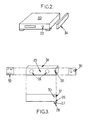
- control device comprises a housing 34.
- the housing 34 has the shape of a rectangular parallelepiped that can be placed indifferently against a face of a device 20, in this case a DVD player, by a bearing face 25.
- the device 20 could be a another device capable of being remotely controlled, such as a home theater or satellite receiver.
- These devices have the characteristic of having the shape of a parallelepiped of a depth of approximately between 20 and 35 cm.
- the apparatus 20 is associated with an infrared remote control, not shown, and provided with an infrared receiver 22, positioned on the front.
- the box 34 includes IPTV functions, of the "set-top box” type, and is adapted to inhibit the infrared receiver 22 of the apparatus 20.
- control device 1 and the first device 3 are integrated in a single housing 34.
- the housing 34 comprises, on one of the large faces of the parallelepiped, magnets 24, represented on the figure 3 .
- the housing 34 can be placed above, possibly below, or on one of the two lateral sides of the apparatus 20. Its attachment is provided by the two magnets 24 adapted to press one of the large faces of the parallelepipedic housing 34 against an upper, lower or side face of the apparatus 20.
- the infrared diode 26, responsible for inhibiting the infrared receiver 22 of the apparatus 20, is positioned behind an orifice 27 of the case 34 on a shoulder 28. This orifice is pierced at an angle and thus shaped to direct the infrared light emitted by the diode 26 to the front of the device 20, on which is the infrared receiver 22.
- the infrared receiver 30 is placed at the bottom of a black funnel 31 to minimize the reflected light which would disturb it.
- the shoulder 28 also serves to ensure a more effective adhesion of the housing 34 to the device 20 especially in case of insertion of a USB key into the front of the housing 34.
- the housing 34 also has in front back a connector 32 for powering the housing 34, and also comprising in the particular example described here a video input jack for connection to the output of the DVD player, a video output jack to a TV and a network jack Ethernet to an internet modem router.
- the operation of the housing 34 is as follows.
- the apparatus 20 is a DVD player.
- the remote control of this DVD player 20 to control the IPTV functions of the casing 34, he starts by classically matching this remote control with the casing 34, either by using a database or by learning .
- the box 34 uses its connection to the television to display various conventional setting menus.
- the DVD player 20 is preferably turned off.
- the remote control Following a prolonged pressing of the user on a specific button of the remote control, it emits a tilt signal which, once received by the housing 34, causes the activation of the means of inhibition thereof.
- the diode 26 then emits infrared light which saturates the receiver 22 of the DVD player 20, the DVD player 20 is then no longer able to receive infrared commands emitted by its remote control.
- the commands issued by this remote control are intended to control the IPTV box. Visually, this results in the display on the TV screen of a specific menu on IPTV.
- buttons on the remote control are used to move around in an IPTV application.
- the remote control Following a further prolonged pressing of the user on the same specific button of the remote control, it emits a new tilt signal which, once received by the housing 34, this time causes the deactivation of the inhibiting means.
- the diode 26 then stops emitting infrared light. As a result, the IPTV application no longer receives commands while the DVD player 20 receives commands from the remote again.
- the user can at will use the DVD player or the IPTV functions of the box 34 with the same remote control.
- control device is integrable in the case of a particular audiovisual function such as, for example, a DVD player, a satellite receiver, an IPTV receiver, etc.
- the inhibiting means are capable of inhibiting the infrared control receiving means of a plurality of devices.
- the infrared source can be oriented so that it illuminates multiple receivers at the same time. It is understood that in this case, all the illuminated devices are then inhibited at the same time.
- the activation and inhibition means are then advantageously programmed so that it is possible to select, at a given instant, one or more of the devices to be inhibited.
- a display device for example the television set
- this display device can present a state.
- the control device and in particular inhibition means for example, a sign, in the form of a strip at the bottom of the screen and a color scheme, advantageously allows the user to determine which devices he can control at this time with his remote control and which are those who are inhibited. In general, this can make it possible to display several states of the device. For example, each family member can save preferences, links to videos to share, and so on. All this information is grouped as a displayable page on the TV.
- the control device comprises power supply control means 19, shown in FIG. figure 1 , to act on a block of electrical outlets on which are connected the various devices around the TV.
- this block of electrical outlets may be to the X10 powerline control standard, so that the device is able to issue commands to turn on or off appliances plugged into the outlets.
- Adapted commands then allow the user, from his remote control, and consulting a dashboard displaying the status of the various devices to remotely control, turn on or off his devices. It is easy to see that this variant advantageously allows energy savings by not leaving devices unnecessarily in a standby mode, while keeping the ergonomics of the commands by infrared.
- the person skilled in the art also knows how to adapt the inhibition means to a particular configuration and replace, for example, the use of an infrared diode to inhibit the reception means by a mechanical system, for example a shutter, or an electronic system such as a transparent or opaque screen depending on a voltage applied.
- a control device has thus been described which advantageously makes it possible to pool the control of several devices around each other. a standard remote thus avoiding, advantageously, the user to purchase a universal remote control.
Landscapes
- Engineering & Computer Science (AREA)
- Signal Processing (AREA)
- Multimedia (AREA)
- Human Computer Interaction (AREA)
- Physics & Mathematics (AREA)
- Computer Networks & Wireless Communication (AREA)
- Electromagnetism (AREA)
- General Physics & Mathematics (AREA)
- Selective Calling Equipment (AREA)
- Details Of Television Systems (AREA)
Applications Claiming Priority (1)
| Application Number | Priority Date | Filing Date | Title |
|---|---|---|---|
| FR0852104 | 2008-03-31 |
Publications (1)
| Publication Number | Publication Date |
|---|---|
| EP2107802A1 true EP2107802A1 (de) | 2009-10-07 |
Family
ID=39929628
Family Applications (1)
| Application Number | Title | Priority Date | Filing Date |
|---|---|---|---|
| EP09156868A Withdrawn EP2107802A1 (de) | 2008-03-31 | 2009-03-31 | Steuervorrichtung für mehrere Geräte mit Hilfe einer Infrarot-Fernsteuerung |
Country Status (1)
| Country | Link |
|---|---|
| EP (1) | EP2107802A1 (de) |
Citations (5)
| Publication number | Priority date | Publication date | Assignee | Title |
|---|---|---|---|---|
| EP0612157A2 (de) | 1993-01-06 | 1994-08-24 | Sony Corporation | Verfahren zur Fernsteuerung von mehreren Audiovisuelgeräten |
| WO2000013344A1 (en) | 1998-08-31 | 2000-03-09 | Sony Electronics, Inc. | Optical remote control interface system and method |
| US6570524B1 (en) * | 1999-06-30 | 2003-05-27 | International Business Machines Corp. | Method for remote communication with an addressable target using a generalized pointing device |
| US20030141987A1 (en) * | 1999-06-16 | 2003-07-31 | Hayes Patrick H. | System and method for automatically setting up a universal remote control |
| US20050024226A1 (en) * | 1998-07-23 | 2005-02-03 | Universal Electronics Inc. | Digital interconnect of entertainment equipment |
-
2009
- 2009-03-31 EP EP09156868A patent/EP2107802A1/de not_active Withdrawn
Patent Citations (6)
| Publication number | Priority date | Publication date | Assignee | Title |
|---|---|---|---|---|
| EP0612157A2 (de) | 1993-01-06 | 1994-08-24 | Sony Corporation | Verfahren zur Fernsteuerung von mehreren Audiovisuelgeräten |
| EP0810739A2 (de) * | 1993-01-06 | 1997-12-03 | Sony Corporation | Verfahren zur Inbetriebnahme einer Systemfunktion eines audiovisuelles Systems und deren Steuerung |
| US20050024226A1 (en) * | 1998-07-23 | 2005-02-03 | Universal Electronics Inc. | Digital interconnect of entertainment equipment |
| WO2000013344A1 (en) | 1998-08-31 | 2000-03-09 | Sony Electronics, Inc. | Optical remote control interface system and method |
| US20030141987A1 (en) * | 1999-06-16 | 2003-07-31 | Hayes Patrick H. | System and method for automatically setting up a universal remote control |
| US6570524B1 (en) * | 1999-06-30 | 2003-05-27 | International Business Machines Corp. | Method for remote communication with an addressable target using a generalized pointing device |
Similar Documents
| Publication | Publication Date | Title |
|---|---|---|
| EP2293414A2 (de) | Vorrichtung zum Abkoppeln mindestens eines Geräts vom Stromnetz, die mindestens einen Ausnahmefunktionsmodus anbietet, konfigurierbare Vorrichtung sowie Konfigurationssystem und -verfahren | |
| EP0766438B1 (de) | Schnurloses Telefonsystem mit einem fernsteuerbaren Peripheriegerät | |
| EP1873615A1 (de) | Vorrichtung zur Einsparung des Standby-Verbrauchs einer Geräteanordnung | |
| WO2012136907A1 (fr) | Procédé et dispositif d'éclairage a leds programmable | |
| WO2001039151A1 (fr) | Telecommande adaptable pour appareils electriques disposant de plusieurs fonctions a commander | |
| FR2466157A1 (fr) | Procede de reception d'un canal dans un ensemble de diffusion de television par cable | |
| EP0732023B1 (de) | Vorrichtung zur umschaltung eines telefonendgerätes mit telefonhörer auf ein zusatzgerät | |
| EP2107802A1 (de) | Steuervorrichtung für mehrere Geräte mit Hilfe einer Infrarot-Fernsteuerung | |
| FR2842371A3 (fr) | Dispositif de commande de terminaux de radio et de television et a modulation de frequence a emission/reception | |
| EP3550537B1 (de) | Drahtlose steuervorrichtung und anordnung, die eine solche vorrichtung sowie eine andere steuervorrichtung umfasst, die an eine elektrische leitung angeschlossen werden kann | |
| FR2989411A1 (fr) | Dispositif de commande de l'ouverture d'une porte. | |
| FR2871327A1 (fr) | Distribution audiovisuelle locale | |
| FR2919097A1 (fr) | Procede de fonctionnement d'un emetteur d'ordres dans une installation domotique et emetteur d'ordres pour sa mise en oeuvre | |
| EP3531215B1 (de) | Funktionsverfahren für ein elektrisches laststeuermodul | |
| FR2695238A1 (fr) | Procédé pour exploiter des signaux de télécommande, dispositif de télécommande, et unités fonctionnelles et installation s'y rapportant. | |
| EP1722340B1 (de) | Betriebsverfahren für eine Hausautomatisierungsanlage und zugehörige Hausautomatisierungsanlage | |
| EP3712083B1 (de) | Elektrisches system mit einer tragbaren hülle, die an die verpackung und den transport von mindestens einem mikromodul zur steuerung elektrischer ladungen angepasst ist, und pairing-bank | |
| EP1253568A2 (de) | Verfahren und Vorrichtung zur Konfigurierung von Fernbedienungsgeräte | |
| FR2950458A1 (fr) | Dispositif de transmission de codes en provenance d'une telecommande | |
| FR3036510A1 (fr) | Procede et dispositif pour selectionner un contenu multimedia secondaire | |
| FR2944169A1 (fr) | Procede et dispositif de deport de telecommande infrarouge numerique universel et systeme de transmission audio/video associe. | |
| FR2819906A1 (fr) | Dispositif d'interaction avec un micro-ordinateur | |
| FR2741767A1 (fr) | Dispositif de simulation des fonctionnalites d'un reseau telephonique | |
| FR2877799A1 (fr) | Boitier autonome de systeme pip | |
| FR2958488A1 (fr) | Systeme de mesure d'audience de chaines televisuelles |
Legal Events
| Date | Code | Title | Description |
|---|---|---|---|
| PUAI | Public reference made under article 153(3) epc to a published international application that has entered the european phase |
Free format text: ORIGINAL CODE: 0009012 |
|
| AK | Designated contracting states |
Kind code of ref document: A1 Designated state(s): AT BE BG CH CY CZ DE DK EE ES FI FR GB GR HR HU IE IS IT LI LT LU LV MC MK MT NL NO PL PT RO SE SI SK TR |
|
| AX | Request for extension of the european patent |
Extension state: AL BA RS |
|
| 17P | Request for examination filed |
Effective date: 20100308 |
|
| RIC1 | Information provided on ipc code assigned before grant |
Ipc: H04N 5/44 20060101AFI20100325BHEP |
|
| GRAC | Information related to communication of intention to grant a patent modified |
Free format text: ORIGINAL CODE: EPIDOSCIGR1 |
|
| GRAP | Despatch of communication of intention to grant a patent |
Free format text: ORIGINAL CODE: EPIDOSNIGR1 |
|
| AKX | Designation fees paid |
Designated state(s): AT BE BG CH CY CZ DE DK EE ES FI FR GB GR HR HU IE IS IT LI LT LU LV MC MK MT NL NO PL PT RO SE SI SK TR |
|
| STAA | Information on the status of an ep patent application or granted ep patent |
Free format text: STATUS: THE APPLICATION IS DEEMED TO BE WITHDRAWN |
|
| 18D | Application deemed to be withdrawn |
Effective date: 20101001 |