EP2107823A2 - Procédé et appareil pour microphones partageant un volume acoustique commun - Google Patents
Procédé et appareil pour microphones partageant un volume acoustique commun Download PDFInfo
- Publication number
- EP2107823A2 EP2107823A2 EP09251027A EP09251027A EP2107823A2 EP 2107823 A2 EP2107823 A2 EP 2107823A2 EP 09251027 A EP09251027 A EP 09251027A EP 09251027 A EP09251027 A EP 09251027A EP 2107823 A2 EP2107823 A2 EP 2107823A2
- Authority
- EP
- European Patent Office
- Prior art keywords
- microphone
- capsule
- module
- microphone module
- subject matter
- Prior art date
- Legal status (The legal status is an assumption and is not a legal conclusion. Google has not performed a legal analysis and makes no representation as to the accuracy of the status listed.)
- Granted
Links
Images



Classifications
-
- H—ELECTRICITY
- H04—ELECTRIC COMMUNICATION TECHNIQUE
- H04R—LOUDSPEAKERS, MICROPHONES, GRAMOPHONE PICK-UPS OR LIKE ACOUSTIC ELECTROMECHANICAL TRANSDUCERS; ELECTRIC HEARING AIDS; PUBLIC ADDRESS SYSTEMS
- H04R25/00—Electric hearing aids
- H04R25/60—Mounting or interconnection of hearing aid parts, e.g. inside tips, housings or to ossicles
-
- H—ELECTRICITY
- H04—ELECTRIC COMMUNICATION TECHNIQUE
- H04R—LOUDSPEAKERS, MICROPHONES, GRAMOPHONE PICK-UPS OR LIKE ACOUSTIC ELECTROMECHANICAL TRANSDUCERS; ELECTRIC HEARING AIDS; PUBLIC ADDRESS SYSTEMS
- H04R1/00—Details of transducers, loudspeakers or microphones
- H04R1/08—Mouthpieces; Microphones; Attachments therefor
-
- H—ELECTRICITY
- H04—ELECTRIC COMMUNICATION TECHNIQUE
- H04R—LOUDSPEAKERS, MICROPHONES, GRAMOPHONE PICK-UPS OR LIKE ACOUSTIC ELECTROMECHANICAL TRANSDUCERS; ELECTRIC HEARING AIDS; PUBLIC ADDRESS SYSTEMS
- H04R25/00—Electric hearing aids
- H04R25/60—Mounting or interconnection of hearing aid parts, e.g. inside tips, housings or to ossicles
- H04R25/604—Mounting or interconnection of hearing aid parts, e.g. inside tips, housings or to ossicles of acoustic or vibrational transducers
-
- H—ELECTRICITY
- H04—ELECTRIC COMMUNICATION TECHNIQUE
- H04R—LOUDSPEAKERS, MICROPHONES, GRAMOPHONE PICK-UPS OR LIKE ACOUSTIC ELECTROMECHANICAL TRANSDUCERS; ELECTRIC HEARING AIDS; PUBLIC ADDRESS SYSTEMS
- H04R2410/00—Microphones
- H04R2410/01—Noise reduction using microphones having different directional characteristics
-
- H—ELECTRICITY
- H04—ELECTRIC COMMUNICATION TECHNIQUE
- H04R—LOUDSPEAKERS, MICROPHONES, GRAMOPHONE PICK-UPS OR LIKE ACOUSTIC ELECTROMECHANICAL TRANSDUCERS; ELECTRIC HEARING AIDS; PUBLIC ADDRESS SYSTEMS
- H04R25/00—Electric hearing aids
- H04R25/60—Mounting or interconnection of hearing aid parts, e.g. inside tips, housings or to ossicles
- H04R25/609—Mounting or interconnection of hearing aid parts, e.g. inside tips, housings or to ossicles of circuitry
-
- Y—GENERAL TAGGING OF NEW TECHNOLOGICAL DEVELOPMENTS; GENERAL TAGGING OF CROSS-SECTIONAL TECHNOLOGIES SPANNING OVER SEVERAL SECTIONS OF THE IPC; TECHNICAL SUBJECTS COVERED BY FORMER USPC CROSS-REFERENCE ART COLLECTIONS [XRACs] AND DIGESTS
- Y10—TECHNICAL SUBJECTS COVERED BY FORMER USPC
- Y10T—TECHNICAL SUBJECTS COVERED BY FORMER US CLASSIFICATION
- Y10T29/00—Metal working
- Y10T29/49—Method of mechanical manufacture
- Y10T29/49002—Electrical device making
- Y10T29/49005—Acoustic transducer
-
- Y—GENERAL TAGGING OF NEW TECHNOLOGICAL DEVELOPMENTS; GENERAL TAGGING OF CROSS-SECTIONAL TECHNOLOGIES SPANNING OVER SEVERAL SECTIONS OF THE IPC; TECHNICAL SUBJECTS COVERED BY FORMER USPC CROSS-REFERENCE ART COLLECTIONS [XRACs] AND DIGESTS
- Y10—TECHNICAL SUBJECTS COVERED BY FORMER USPC
- Y10T—TECHNICAL SUBJECTS COVERED BY FORMER US CLASSIFICATION
- Y10T29/00—Metal working
- Y10T29/49—Method of mechanical manufacture
- Y10T29/49002—Electrical device making
- Y10T29/49117—Conductor or circuit manufacturing
-
- Y—GENERAL TAGGING OF NEW TECHNOLOGICAL DEVELOPMENTS; GENERAL TAGGING OF CROSS-SECTIONAL TECHNOLOGIES SPANNING OVER SEVERAL SECTIONS OF THE IPC; TECHNICAL SUBJECTS COVERED BY FORMER USPC CROSS-REFERENCE ART COLLECTIONS [XRACs] AND DIGESTS
- Y10—TECHNICAL SUBJECTS COVERED BY FORMER USPC
- Y10T—TECHNICAL SUBJECTS COVERED BY FORMER US CLASSIFICATION
- Y10T29/00—Metal working
- Y10T29/49—Method of mechanical manufacture
- Y10T29/4957—Sound device making
- Y10T29/49572—Hearing aid component making
Definitions
- the present subject matter relates to hearing assistance devices and in particular to method and apparatus for microphones sharing a common acoustic volume.
- Hearing assistance devices are used to improve hearing for wearers. Such devices include, but are not limited to, hearing aids. Hearing assistance devices include microphones and electronics for processing the sound produced by the microphones. The processed sound signals are played to the wearer to provide improved hearing for the wearer.
- the microphones of such devices are very important since they can enhance the sound picked up by the hearing assistance device and, in some cases, can reduce problems with room noise and acoustic feedback when used properly.
- Each omnidirectional microphone requires at least one microphone port for reception of sound.
- Directional microphones require at least two microphone ports. The positioning and design of microphone ports and microphones in hearing assistance devices are complicated by space and performance limitations.
- Such improved microphones should include enhanced space utilization and performance and should be easy to manufacture.
- the present subject matter provides method and apparatus for improved microphones sharing an acoustic volume. Some embodiments are useful for hearing assistance devices. Examples of an improved microphone module offering omnidirectional and directional microphone capsules are provided. Different mounting and interconnection embodiments are provided. Different electrical connector embodiments are discussed. Improvements in space and performance, and other efficiencies, are provided by the teachings set forth herein.
- FIG. 1A is a diagram showing a top view of a microphone module including conjoined microphone capsules according to one embodiment of the present subject matter.
- Microphone module 10 includes a first microphone capsule 1 and a second microphone capsule 2.
- Microphone capsule 1 has a first opening 5 for reception of sound. It is designed to include a second opening 6 which will pass sound from the first capsule 1 to the second capsule 2.
- Capsule 2 has a first opening 7 which is aligned to receive sound from second opening 6. Sound enters into capsule 2 via first opening 5 and second opening 8.
- both capsule 1 and capsule 2 are modified to provide a conjoined microphone 10 that demonstrates enhanced performance and form factor over separate microphones and over standard separate microphones that are acoustically coupled.
- capsule 1 includes a slit for second opening 6 and a slit for first opening 7.
- the slits are aligned and acoustically sealed together to provide effective sound transfer between capsule 1 and capsule 2.
- Various sealing methods may be employed, including, but not limited to, gluing the capsules together in proper alignment.
- Rear port 114 is used to couple a sound opening on the hearing assistance device to the first opening 5.
- Slots 112 are used to mount the capsules 1 and 2 in a modular assembly.
- Solder pads 110 provide electrical contact points for the various microphones. These contacts can be soldered or connected via other connection techniques, such as connection via one or more flexible conductive tapes.
- One such technique includes the use of conductive silicone connections. Examples of conductive silicone connections include, but are not limited to, those provided in U.S. Patent Application Ser. No. 12/027,173 filed Feb. 6, 2008 , entitled: ELECTRICAL CONTACTS USING CONDUCTIVE SILICONE IN HEARING ASSISTANCE DEVICES, the entire disclosure of which is hereby incorporated by reference in its entirety. Other contacts and connection methods are possible without departing from the scope of the present subject matter.
- Position 3 includes a slot in the case of 1.04 x 0.27 mm
- Position W3 includes a slot in the case of 2 x 0.27 mm
- Position W9 includes a slot in the case of 2 x 0.27 mm
- position 9T includes a hole in the case of diameter 0.5 mm.
- Other dimensions are possible without departing from the scope of the present subject matter.
- FIG. 1B is a diagram showing a side view of a microphone module including conjoined microphone capsules according to one embodiment of the present subject matter.
- a connection plate 120 is used to connect the first and second capsule together.
- the connection plate is about 4.8 x 2.3 x 0.14 mm.
- Other dimensions and shapes of connection plates are possible without departing from the scope of the present subject matter.
- FIGS. 1A and 1B are intended to demonstrate one geometry and configuration. Other geometries and configurations are possible without departing from the scope of the present subject matter.
- an omnidirectional-omnidirectional microphone capsule combination is used.
- a directional-directional microphone capsule combination is used.
- an omnidirectional-directional microphone capsule combination is used.
- the order of the directional and omnidirectional microphones is reversed.
- FIG. 1C is a diagram showing a top view of a microphone module including conjoined omnidirectional and directional microphones according to one embodiment of the present subject matter.
- Microphone module 100 includes a directional capsule 102 and an omnidirectional capsule 104.
- Omnidirectional microphone capsule 104 has a first omni opening 105 for reception of sound. It is modified to include a second omni opening 106 which will pass sound from the omnidirectional capsule 104 to directional capsule 102.
- Directional capsule 102 in turn has a first directional opening 107 which is aligned to receive sound from second omni opening 106. Sound enters into directional capsule 102 via first omni opening 105 and second directional opening 108 and provides a directional output signal indicative of the sound received at both openings.
- both omnidirectional capsule 104 and directional capsule 102 are modified to provide a conjoined microphone 100 that demonstrates enhanced performance over separate microphones and over standard separate microphones that are acoustically coupled.
- omnidirectional capsule 104 includes a slit for second omni opening 106 and a slit for first directional opening 107.
- the slits are aligned and acoustically sealed together to provide effective sound transfer from the omnidirectional microphone to the directional microphone.
- Such designs provide a compact and efficient conjoined microphone assembly.
- Various sealing methods may be employed, including, but not limited to, gluing the capsules together in proper alignment.
- Rear port 114 is used to couple a sound opening on the hearing assistance device to the first omni opening 105.
- Rear port 114 is depicted as a large diameter spout. It is understood that the diameter of the spout providing sound to the omnidirectional microphone is also adapted to provide sufficient sound to the directional microphone via the omnidirectional microphone.
- the second directional opening 108 may be of smaller size in various embodiments.
- Solder pads 110 provide electrical contact points for the various microphones. These contacts can be soldered or connected via other connection techniques, such as connection via one or more flexible conductive tapes.
- connection techniques such as connection via one or more flexible conductive tapes.
- One such technique includes the use of conductive silicone connections. Examples of conductive silicone connections include, but are not limited to, those provided in U.S. Patent Application Ser. No. 12/027,173 filed Feb. 6, 2008 , entitled: ELECTRICAL CONTACTS USING CONDUCTIVE SILICONE IN HEARING ASSISTANCE DEVICES, the entire disclosure of which is hereby incorporated by reference in its entirety. Other contacts and connection methods are possible without departing from the scope of the present subject matter.
- Position 3 includes a slot in the case of 1.04 x 0.27 mm
- Position W3 includes a slot in the case of 2 x 0.27 mm
- Position W9 includes a slot in the case of 2 x 0.27 mm
- position 9T includes a hole in the case of diameter 0.5 mm.
- Other dimensions are possible without departing from the scope of the present subject matter.
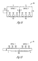
- FIG. 1D is a diagram showing a side view of a microphone module including conjoined omnidirectional and directional microphones according to one embodiment of the present subject matter.
- a connection plate 120 is used to connect the first and second capsules together.
- the connection plate is about 4.8 x 2.3 x 0.14 mm.
- Other dimensions and shapes of connection plates are possible without departing from the scope of the present subject matter.
- FIGS. 1A to 1D are intended to demonstrate one geometry and configuration. Other geometries and configurations are possible without departing from the scope of the present subject matter. Other variations are possible without departing from the scope of the present subject matter.
- FIG. 2 is a perspective cutaway view of a design for a conjoined microphone module according to one embodiment of the present subject matter.
- Conjoined microphone 200 includes an omnidirectional capsule 104 connected to a directional capsule 102, in various embodiments as set forth herein.
- the module is packaged to include a rear port 205 and a front port 208.
- the design of FIG. 2 is depicted as a surface mount hybrid module, which has contacts 210 showing on the lower surface.
- contacts 210 are connected to solder pads 110 in various combinations to provide interconnections to the various capsules of the module.
- the dimensions of the sound chamber for the directional microphone can use the dimensions of the sound chamber of the omnidirectional microphone.
- the resulting compact design is efficient in terms of space and power and provides ease of manufacturing and assembly since only two sound ports are required to be acoustically connected to the resulting hearing assistance device. It is understood that a variety of connections can be employed to the module, and that it is not limited to surface mounting.
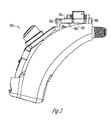
- FIG. 3 is a cutaway view of the behind-the-ear portion of a hearing assistance device using the microphone module of FIG. 2 , according to one embodiment of the present subject matter.
- microphone module 200 is shown mounted in a behind-the-ear hearing assistance device 300. It is understood that this device is used to demonstrate the use of the microphone module, and that other devices are possible without departing from the scope of the present subject matter.
- the microphone module of the present subject matter could be mounted in a behind-the-ear component of a receiver-in-canal (RIC) type device.
- the microphone module of the present subject matter could be mounted in an over-the-ear or on-the-ear component of a hearing assistance device.
- RIC receiver-in-canal
- One advantage of the design of FIG. 3 is that only two microphone ports 205 and 208 need to be connected to openings in the case of BTE 300, thereby simplifying design and assembly.
- the contacts 210 (not shown) can be connected by any of the connection methodologies set forth herein and including those that are known in the art.
- Another advantage of the design of FIG. 3 is that the microphone module can be assembled in a substantially lower profile than-previous designs. Other advantages exist that are not expressly set forth herein.
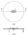
- FIGS. 4A and 4B show different views of an in-the-ear (ITE) faceplate using a microphone module according to one embodiment of the present subject matter.
- FIG. 4A is a plan or top view of one example of an ITE faceplate including a microphone module 400.
- FIG. 4B is a cross section showing at least two sound ports 402 and 404 configured into the faceplate to acoustically connect to the ports of the microphone module 400. Other configurations of sound ports and numbers of ports are possible without departing from the scope of the present subject matter.
- FIG. 5 is a block diagram of a second order microphone module 500 according to one embodiment of the present subject matter.
- the discussion above for omni capsule 104 and directional capsule 102 is incorporated herein by reference.
- another directional microphone, directional microphone capsule 506 is added to the design of FIG. 1 to create a second order microphone module 500.
- the second directional opening 108 of directional capsule 102 is connected to a third port 530.
- the second directional opening 511 of directional capsule 506 is also connected to third port 530.
- These ports are connected in an acoustically sealed fashion, as is depicted by sealed area 512.
- the resulting microphone module has three acoustic ports 510, 105, and 530.
- Electrical pads 110 are used to connect to each microphone. As demonstrated herein, these pads may be combined to common contacts where appropriate in hybrid packaging and connected as described herein.
- Various slots or other mounting assemblies may be employed to place the modules within an assembly.
- FIG. 6 is a block diagram of a second order microphone module 600 according to one embodiment of the present subject matter. It provides a variation of the design 500 of FIG. 5 for purposes of demonstration.
- the order of the microphones is varied to provide an omni capsule 601 situated between a first directional microphone capsule 602 and a second directional microphone capsule 603.
- the sealed area 612 provides for an acoustic input port 630 for modules 601 and 603.
- this design has three acoustic ports 610, 620, and 630.
- Electrical pads 110 are used to connect to each microphone. As demonstrated herein, these pads may be combined to common contacts where appropriate in hybrid packaging and connected as described herein.
- Various slots or other mounting assemblies may be employed to place the modules within an assembly.
- acoustic ports 530 and 630 can be located in different positions relative to the other ports to achieve different port spacings, as may be desirable in different designs. This is demonstrated as port 640 in FIG. 6 .
- Port 640 provides an alternative to port 630 in that it provides an acoustic port closer to port 620 where such applications are beneficial.
- Other port positions are possible without departing from the scope of the present subject matter.
- the present microphone module may employ a dual diaphragm that shares one or more volumes and/or one or more acoustic openings. Such designs are less prone to degradation in directional performance from exposure to demanding environments such as elevated temperatures and high humidities. Such designs offer lower overall noise than dual-omni systems due to the involvement of only one microphone and one input circuit stage in such embodiments. Overall design is more straightforward because there are fewer acoustic coupling areas between the microphone module and the hearing assistance device. A lower profile design is possible which is more cosmetically appealing.
- EIN equivalent input noise
- the omnidirectional microphone may function as a buffer to provide more stable directional performance and a design which is less susceptible to hazardous environments, such as high humidity, sweat, and wind.
- higher order directional modules can be constructed using the teachings provided herein. Such designs may employ one or more additional matched differential microphones. Such systems have benefits over multiple omnidirectional microphone designs, including, but not limited to: fewer microphones are required, less microphone matchings are necessary, performance is more stable as discussed herein, lower system EIN, simpler algorithm designs can be employed, and potentially lower overall costs can be met.
- hearing assistance devices including but not limited to, cochlear implant type hearing devices, hearing aids, such as behind-the-ear (BTE), in-the-ear (ITE), in-the-canal (ITC), or completely-in-the-canal (CIC) type hearing aids.
- BTE behind-the-ear
- ITE in-the-ear
- ITC in-the-canal
- CIC completely-in-the-canal
- hearing assistance devices including but not limited to, cochlear implant type hearing devices, hearing aids, such as behind-the-ear (BTE), in-the-ear (ITE), in-the-canal (ITC), or completely-in-the-canal (CIC) type hearing aids.
- BTE behind-the-ear
- ITE in-the-ear
- ITC in-the-canal
- CIC completely-in-the-canal
- hearing assistance devices may fall within the scope of the present subject matter.
Landscapes
- Physics & Mathematics (AREA)
- Engineering & Computer Science (AREA)
- Acoustics & Sound (AREA)
- Signal Processing (AREA)
- Health & Medical Sciences (AREA)
- General Health & Medical Sciences (AREA)
- Neurosurgery (AREA)
- Otolaryngology (AREA)
- Electrostatic, Electromagnetic, Magneto- Strictive, And Variable-Resistance Transducers (AREA)
- Details Of Audible-Bandwidth Transducers (AREA)
Applications Claiming Priority (1)
| Application Number | Priority Date | Filing Date | Title |
|---|---|---|---|
| US4180808P | 2008-04-02 | 2008-04-02 |
Publications (3)
| Publication Number | Publication Date |
|---|---|
| EP2107823A2 true EP2107823A2 (fr) | 2009-10-07 |
| EP2107823A3 EP2107823A3 (fr) | 2010-01-13 |
| EP2107823B1 EP2107823B1 (fr) | 2013-06-19 |
Family
ID=40910779
Family Applications (1)
| Application Number | Title | Priority Date | Filing Date |
|---|---|---|---|
| EP09251027.0A Not-in-force EP2107823B1 (fr) | 2008-04-02 | 2009-04-01 | Procédé et appareil pour microphones partageant un volume acoustique commun |
Country Status (3)
| Country | Link |
|---|---|
| US (2) | US8254609B2 (fr) |
| EP (1) | EP2107823B1 (fr) |
| DK (1) | DK2107823T3 (fr) |
Cited By (3)
| Publication number | Priority date | Publication date | Assignee | Title |
|---|---|---|---|---|
| WO2012139230A1 (fr) | 2011-04-14 | 2012-10-18 | Phonak Ag | Instrument auditif |
| EP3057339A1 (fr) | 2015-02-10 | 2016-08-17 | Sonion Nederland B.V. | Module de microphone avec agencement d'entrée acoustique intermédiaire partagé |
| EP3057338A1 (fr) * | 2015-02-10 | 2016-08-17 | Sonion Nederland B.V. | Module de microphone directionnel |
Families Citing this family (10)
| Publication number | Priority date | Publication date | Assignee | Title |
|---|---|---|---|---|
| US8254609B2 (en) | 2008-04-02 | 2012-08-28 | Starkey Laboratories, Inc. | Microphones sharing a common acoustic part and volume |
| CA2639555A1 (fr) | 2008-08-11 | 2008-12-15 | Hyman Ngo | Applique et emblemes lithographiques haute definition |
| US8781141B2 (en) | 2008-08-27 | 2014-07-15 | Starkey Laboratories, Inc. | Modular connection assembly for a hearing assistance device |
| DK2324643T3 (en) * | 2008-09-18 | 2014-11-17 | Siemens Medical Instr Pte Ltd | A hearing aid faceplate arrangement |
| US9049526B2 (en) * | 2011-03-19 | 2015-06-02 | Starkey Laboratories, Inc. | Compact programming block connector for hearing assistance devices |
| US9066185B2 (en) * | 2012-05-22 | 2015-06-23 | Otokinetics Inc. | Implantable microphone |
| EP2723102B1 (fr) * | 2012-10-18 | 2018-09-05 | Sonion Nederland B.V. | Transducteur, appareil auditif comprenant un transducteur et procédé permettant de faire fonctionner le transducteur |
| US9491880B2 (en) * | 2014-08-12 | 2016-11-08 | Google Technology Holdings LLC | Circuit assembly for compact acoustic device |
| DK3065418T3 (da) * | 2015-03-05 | 2020-07-06 | Oticon As | Mikrofonindgang til høreapparat |
| US10785562B1 (en) * | 2017-12-08 | 2020-09-22 | Verily Life Sciences Llc | Position-aware recording devices able to provide context to speech |
Citations (1)
| Publication number | Priority date | Publication date | Assignee | Title |
|---|---|---|---|---|
| US2717308A (en) | 1950-04-12 | 1955-09-06 | Joseph D Kevorkian | Lamp guard construction |
Family Cites Families (15)
| Publication number | Priority date | Publication date | Assignee | Title |
|---|---|---|---|---|
| US3770911A (en) * | 1972-07-21 | 1973-11-06 | Industrial Research Prod Inc | Hearing aid system |
| JPH07104582A (ja) | 1993-09-29 | 1995-04-21 | Ricoh Co Ltd | 画像形成装置 |
| EP1330940B1 (fr) | 2000-10-05 | 2012-03-07 | Etymotic Research, Inc | Ensemble microphone directionnel |
| EP1821570B1 (fr) | 2000-11-28 | 2017-02-08 | Knowles Electronics, LLC | Microphone de condensateur en silicone miniature et son procédé de production |
| US6937735B2 (en) * | 2001-04-18 | 2005-08-30 | SonionMicrotronic Néderland B.V. | Microphone for a listening device having a reduced humidity coefficient |
| EP1459595B1 (fr) * | 2001-12-07 | 2005-05-18 | Oticon A/S | Procede permettant de produire une prothese auditive |
| US7181030B2 (en) * | 2002-01-12 | 2007-02-20 | Oticon A/S | Wind noise insensitive hearing aid |
| DE10260304B3 (de) | 2002-12-20 | 2004-07-08 | Siemens Audiologische Technik Gmbh | Hörgerätesystem mit seitenspezifisch ausgebildeten hinter den Ohren tragbaren Hörhilfegeräten |
| US9099094B2 (en) * | 2003-03-27 | 2015-08-04 | Aliphcom | Microphone array with rear venting |
| EP1643798B1 (fr) | 2004-10-01 | 2012-12-05 | AKG Acoustics GmbH | Microphone comprenant deux capsules microphoniques à gradient de pression |
| JP4150407B2 (ja) * | 2005-06-20 | 2008-09-17 | ホシデン株式会社 | 電気音響変換器 |
| WO2007024909A1 (fr) * | 2005-08-23 | 2007-03-01 | Analog Devices, Inc. | Systeme multi-microphones |
| JP4468280B2 (ja) * | 2005-10-07 | 2010-05-26 | パナソニック株式会社 | マイクロホン装置 |
| US8494195B2 (en) | 2007-02-07 | 2013-07-23 | Starkey Laboratories, Inc. | Electrical contacts using conductive silicone in hearing assistance devices |
| US8254609B2 (en) | 2008-04-02 | 2012-08-28 | Starkey Laboratories, Inc. | Microphones sharing a common acoustic part and volume |
-
2009
- 2009-04-01 US US12/416,267 patent/US8254609B2/en not_active Expired - Fee Related
- 2009-04-01 EP EP09251027.0A patent/EP2107823B1/fr not_active Not-in-force
- 2009-04-01 DK DK09251027.0T patent/DK2107823T3/da active
-
2012
- 2012-08-27 US US13/595,905 patent/US9491555B2/en active Active
Patent Citations (1)
| Publication number | Priority date | Publication date | Assignee | Title |
|---|---|---|---|---|
| US2717308A (en) | 1950-04-12 | 1955-09-06 | Joseph D Kevorkian | Lamp guard construction |
Cited By (8)
| Publication number | Priority date | Publication date | Assignee | Title |
|---|---|---|---|---|
| WO2012139230A1 (fr) | 2011-04-14 | 2012-10-18 | Phonak Ag | Instrument auditif |
| CN103597856A (zh) * | 2011-04-14 | 2014-02-19 | 福纳克股份公司 | 听力工具 |
| EP2697983A1 (fr) * | 2011-04-14 | 2014-02-19 | Phonak AG | Instrument auditif |
| CN103597856B (zh) * | 2011-04-14 | 2017-07-04 | 福纳克股份公司 | 听力工具 |
| US9781523B2 (en) | 2011-04-14 | 2017-10-03 | Sonova Ag | Hearing instrument |
| EP3057339A1 (fr) | 2015-02-10 | 2016-08-17 | Sonion Nederland B.V. | Module de microphone avec agencement d'entrée acoustique intermédiaire partagé |
| EP3057338A1 (fr) * | 2015-02-10 | 2016-08-17 | Sonion Nederland B.V. | Module de microphone directionnel |
| US10136213B2 (en) | 2015-02-10 | 2018-11-20 | Sonion Nederland B.V. | Microphone module with shared middle sound inlet arrangement |
Also Published As
| Publication number | Publication date |
|---|---|
| US9491555B2 (en) | 2016-11-08 |
| US20090252365A1 (en) | 2009-10-08 |
| US20130108089A1 (en) | 2013-05-02 |
| US8254609B2 (en) | 2012-08-28 |
| EP2107823B1 (fr) | 2013-06-19 |
| EP2107823A3 (fr) | 2010-01-13 |
| DK2107823T3 (da) | 2013-09-30 |
Similar Documents
| Publication | Publication Date | Title |
|---|---|---|
| EP2107823B1 (fr) | Procédé et appareil pour microphones partageant un volume acoustique commun | |
| EP1169886B2 (fr) | Microphone pour prothese auditive | |
| EP1349426B1 (fr) | Prothèse auditive avec des microphones directionnels | |
| US9408004B2 (en) | Flex connector for a hearing assistance device | |
| US9949051B2 (en) | Embedded and printed acoustic port | |
| CN106162479A (zh) | 助听器 | |
| US20100208927A1 (en) | Microphone module for a hearing device | |
| US20150256952A1 (en) | Hearing instrument having a routing building block for complex mid structures | |
| US9055357B2 (en) | Multi-directional and omnidirectional hybrid microphone for hearing assistance devices | |
| US12069441B2 (en) | Hearing device earpiece and receiver with vent assembly | |
| US12598411B2 (en) | Hearing device comprising a partition | |
| EP2324643B1 (fr) | Agencement de dalle pour aide auditive | |
| EP4270994A1 (fr) | Dispositif pouvant être porté sur l'oreille avec piège à matière étrangère | |
| EP1988743A3 (fr) | Système de prothese auditive | |
| WO2006004327A1 (fr) | Prothese auditive ameliorant la perception directionnelle | |
| WO2009123561A1 (fr) | Prothèse auditive | |
| US20240179481A1 (en) | Small meander line antenna for in-the-ear hearing device | |
| US12212919B2 (en) | Ear-worn hearing device with multiple transducers | |
| US8605926B2 (en) | Sealing unit with component mount for a hearing apparatus | |
| JP2022087069A (ja) | 中間モジュールを有する聴覚装置イヤピース | |
| CN119521063A (zh) | 用于听力装置的rie耳塞 | |
| CN116801176A (zh) | 听力设备 | |
| CN111163412A (zh) | 多通道助听装置 |
Legal Events
| Date | Code | Title | Description |
|---|---|---|---|
| PUAI | Public reference made under article 153(3) epc to a published international application that has entered the european phase |
Free format text: ORIGINAL CODE: 0009012 |
|
| 17P | Request for examination filed |
Effective date: 20090407 |
|
| AK | Designated contracting states |
Kind code of ref document: A2 Designated state(s): AT BE BG CH CY CZ DE DK EE ES FI FR GB GR HR HU IE IS IT LI LT LU LV MC MK MT NL NO PL PT RO SE SI SK TR |
|
| PUAL | Search report despatched |
Free format text: ORIGINAL CODE: 0009013 |
|
| AK | Designated contracting states |
Kind code of ref document: A3 Designated state(s): AT BE BG CH CY CZ DE DK EE ES FI FR GB GR HR HU IE IS IT LI LT LU LV MC MK MT NL NO PL PT RO SE SI SK TR |
|
| RIC1 | Information provided on ipc code assigned before grant |
Ipc: H04R 1/26 20060101AFI20090807BHEP Ipc: H04R 25/00 20060101ALI20091208BHEP |
|
| 17Q | First examination report despatched |
Effective date: 20100716 |
|
| RIC1 | Information provided on ipc code assigned before grant |
Ipc: H04R 1/08 20060101AFI20121108BHEP Ipc: H04R 25/00 20060101ALN20121108BHEP |
|
| REG | Reference to a national code |
Ref country code: DE Ref legal event code: R079 Ref document number: 602009016500 Country of ref document: DE Free format text: PREVIOUS MAIN CLASS: H04R0001260000 Ipc: H04R0001080000 |
|
| GRAP | Despatch of communication of intention to grant a patent |
Free format text: ORIGINAL CODE: EPIDOSNIGR1 |
|
| RIC1 | Information provided on ipc code assigned before grant |
Ipc: H04R 1/08 20060101AFI20121220BHEP Ipc: H04R 25/00 20060101ALI20121220BHEP |
|
| GRAS | Grant fee paid |
Free format text: ORIGINAL CODE: EPIDOSNIGR3 |
|
| GRAA | (expected) grant |
Free format text: ORIGINAL CODE: 0009210 |
|
| AK | Designated contracting states |
Kind code of ref document: B1 Designated state(s): AT BE BG CH CY CZ DE DK EE ES FI FR GB GR HR HU IE IS IT LI LT LU LV MC MK MT NL NO PL PT RO SE SI SK TR |
|
| REG | Reference to a national code |
Ref country code: GB Ref legal event code: FG4D |
|
| REG | Reference to a national code |
Ref country code: CH Ref legal event code: EP |
|
| REG | Reference to a national code |
Ref country code: AT Ref legal event code: REF Ref document number: 618210 Country of ref document: AT Kind code of ref document: T Effective date: 20130715 |
|
| REG | Reference to a national code |
Ref country code: IE Ref legal event code: FG4D |
|
| REG | Reference to a national code |
Ref country code: DE Ref legal event code: R096 Ref document number: 602009016500 Country of ref document: DE Effective date: 20130814 |
|
| REG | Reference to a national code |
Ref country code: CH Ref legal event code: NV Representative=s name: MARKS AND CLERK (LUXEMBOURG) LLP, CH |
|
| REG | Reference to a national code |
Ref country code: DK Ref legal event code: T3 Effective date: 20130923 Ref country code: DK Ref legal event code: T3 |
|
| REG | Reference to a national code |
Ref country code: NL Ref legal event code: T3 |
|
| PG25 | Lapsed in a contracting state [announced via postgrant information from national office to epo] |
Ref country code: LT Free format text: LAPSE BECAUSE OF FAILURE TO SUBMIT A TRANSLATION OF THE DESCRIPTION OR TO PAY THE FEE WITHIN THE PRESCRIBED TIME-LIMIT Effective date: 20130619 Ref country code: FI Free format text: LAPSE BECAUSE OF FAILURE TO SUBMIT A TRANSLATION OF THE DESCRIPTION OR TO PAY THE FEE WITHIN THE PRESCRIBED TIME-LIMIT Effective date: 20130619 Ref country code: ES Free format text: LAPSE BECAUSE OF FAILURE TO SUBMIT A TRANSLATION OF THE DESCRIPTION OR TO PAY THE FEE WITHIN THE PRESCRIBED TIME-LIMIT Effective date: 20130930 Ref country code: NO Free format text: LAPSE BECAUSE OF FAILURE TO SUBMIT A TRANSLATION OF THE DESCRIPTION OR TO PAY THE FEE WITHIN THE PRESCRIBED TIME-LIMIT Effective date: 20130919 Ref country code: SI Free format text: LAPSE BECAUSE OF FAILURE TO SUBMIT A TRANSLATION OF THE DESCRIPTION OR TO PAY THE FEE WITHIN THE PRESCRIBED TIME-LIMIT Effective date: 20130619 Ref country code: SE Free format text: LAPSE BECAUSE OF FAILURE TO SUBMIT A TRANSLATION OF THE DESCRIPTION OR TO PAY THE FEE WITHIN THE PRESCRIBED TIME-LIMIT Effective date: 20130619 Ref country code: GR Free format text: LAPSE BECAUSE OF FAILURE TO SUBMIT A TRANSLATION OF THE DESCRIPTION OR TO PAY THE FEE WITHIN THE PRESCRIBED TIME-LIMIT Effective date: 20130920 |
|
| REG | Reference to a national code |
Ref country code: AT Ref legal event code: MK05 Ref document number: 618210 Country of ref document: AT Kind code of ref document: T Effective date: 20130619 |
|
| REG | Reference to a national code |
Ref country code: LT Ref legal event code: MG4D |
|
| PG25 | Lapsed in a contracting state [announced via postgrant information from national office to epo] |
Ref country code: BG Free format text: LAPSE BECAUSE OF FAILURE TO SUBMIT A TRANSLATION OF THE DESCRIPTION OR TO PAY THE FEE WITHIN THE PRESCRIBED TIME-LIMIT Effective date: 20130919 Ref country code: HR Free format text: LAPSE BECAUSE OF FAILURE TO SUBMIT A TRANSLATION OF THE DESCRIPTION OR TO PAY THE FEE WITHIN THE PRESCRIBED TIME-LIMIT Effective date: 20130619 |
|
| PG25 | Lapsed in a contracting state [announced via postgrant information from national office to epo] |
Ref country code: LV Free format text: LAPSE BECAUSE OF FAILURE TO SUBMIT A TRANSLATION OF THE DESCRIPTION OR TO PAY THE FEE WITHIN THE PRESCRIBED TIME-LIMIT Effective date: 20130619 |
|
| PG25 | Lapsed in a contracting state [announced via postgrant information from national office to epo] |
Ref country code: CZ Free format text: LAPSE BECAUSE OF FAILURE TO SUBMIT A TRANSLATION OF THE DESCRIPTION OR TO PAY THE FEE WITHIN THE PRESCRIBED TIME-LIMIT Effective date: 20130619 Ref country code: CY Free format text: LAPSE BECAUSE OF FAILURE TO SUBMIT A TRANSLATION OF THE DESCRIPTION OR TO PAY THE FEE WITHIN THE PRESCRIBED TIME-LIMIT Effective date: 20130807 Ref country code: PT Free format text: LAPSE BECAUSE OF FAILURE TO SUBMIT A TRANSLATION OF THE DESCRIPTION OR TO PAY THE FEE WITHIN THE PRESCRIBED TIME-LIMIT Effective date: 20131021 Ref country code: EE Free format text: LAPSE BECAUSE OF FAILURE TO SUBMIT A TRANSLATION OF THE DESCRIPTION OR TO PAY THE FEE WITHIN THE PRESCRIBED TIME-LIMIT Effective date: 20130619 Ref country code: IS Free format text: LAPSE BECAUSE OF FAILURE TO SUBMIT A TRANSLATION OF THE DESCRIPTION OR TO PAY THE FEE WITHIN THE PRESCRIBED TIME-LIMIT Effective date: 20131019 Ref country code: AT Free format text: LAPSE BECAUSE OF FAILURE TO SUBMIT A TRANSLATION OF THE DESCRIPTION OR TO PAY THE FEE WITHIN THE PRESCRIBED TIME-LIMIT Effective date: 20130619 Ref country code: SK Free format text: LAPSE BECAUSE OF FAILURE TO SUBMIT A TRANSLATION OF THE DESCRIPTION OR TO PAY THE FEE WITHIN THE PRESCRIBED TIME-LIMIT Effective date: 20130619 Ref country code: BE Free format text: LAPSE BECAUSE OF FAILURE TO SUBMIT A TRANSLATION OF THE DESCRIPTION OR TO PAY THE FEE WITHIN THE PRESCRIBED TIME-LIMIT Effective date: 20130619 |
|
| PG25 | Lapsed in a contracting state [announced via postgrant information from national office to epo] |
Ref country code: PL Free format text: LAPSE BECAUSE OF FAILURE TO SUBMIT A TRANSLATION OF THE DESCRIPTION OR TO PAY THE FEE WITHIN THE PRESCRIBED TIME-LIMIT Effective date: 20130619 Ref country code: RO Free format text: LAPSE BECAUSE OF FAILURE TO SUBMIT A TRANSLATION OF THE DESCRIPTION OR TO PAY THE FEE WITHIN THE PRESCRIBED TIME-LIMIT Effective date: 20130619 |
|
| PG25 | Lapsed in a contracting state [announced via postgrant information from national office to epo] |
Ref country code: CY Free format text: LAPSE BECAUSE OF FAILURE TO SUBMIT A TRANSLATION OF THE DESCRIPTION OR TO PAY THE FEE WITHIN THE PRESCRIBED TIME-LIMIT Effective date: 20130619 |
|
| PLBE | No opposition filed within time limit |
Free format text: ORIGINAL CODE: 0009261 |
|
| STAA | Information on the status of an ep patent application or granted ep patent |
Free format text: STATUS: NO OPPOSITION FILED WITHIN TIME LIMIT |
|
| 26N | No opposition filed |
Effective date: 20140320 |
|
| PG25 | Lapsed in a contracting state [announced via postgrant information from national office to epo] |
Ref country code: IT Free format text: LAPSE BECAUSE OF FAILURE TO SUBMIT A TRANSLATION OF THE DESCRIPTION OR TO PAY THE FEE WITHIN THE PRESCRIBED TIME-LIMIT Effective date: 20130619 |
|
| REG | Reference to a national code |
Ref country code: DE Ref legal event code: R097 Ref document number: 602009016500 Country of ref document: DE Effective date: 20140320 |
|
| PG25 | Lapsed in a contracting state [announced via postgrant information from national office to epo] |
Ref country code: LU Free format text: LAPSE BECAUSE OF FAILURE TO SUBMIT A TRANSLATION OF THE DESCRIPTION OR TO PAY THE FEE WITHIN THE PRESCRIBED TIME-LIMIT Effective date: 20140401 Ref country code: MC Free format text: LAPSE BECAUSE OF FAILURE TO SUBMIT A TRANSLATION OF THE DESCRIPTION OR TO PAY THE FEE WITHIN THE PRESCRIBED TIME-LIMIT Effective date: 20130619 |
|
| REG | Reference to a national code |
Ref country code: IE Ref legal event code: MM4A |
|
| PG25 | Lapsed in a contracting state [announced via postgrant information from national office to epo] |
Ref country code: IE Free format text: LAPSE BECAUSE OF NON-PAYMENT OF DUE FEES Effective date: 20140401 |
|
| PG25 | Lapsed in a contracting state [announced via postgrant information from national office to epo] |
Ref country code: MT Free format text: LAPSE BECAUSE OF FAILURE TO SUBMIT A TRANSLATION OF THE DESCRIPTION OR TO PAY THE FEE WITHIN THE PRESCRIBED TIME-LIMIT Effective date: 20130619 |
|
| REG | Reference to a national code |
Ref country code: FR Ref legal event code: PLFP Year of fee payment: 8 |
|
| PGFP | Annual fee paid to national office [announced via postgrant information from national office to epo] |
Ref country code: NL Payment date: 20160426 Year of fee payment: 8 |
|
| PG25 | Lapsed in a contracting state [announced via postgrant information from national office to epo] |
Ref country code: HU Free format text: LAPSE BECAUSE OF FAILURE TO SUBMIT A TRANSLATION OF THE DESCRIPTION OR TO PAY THE FEE WITHIN THE PRESCRIBED TIME-LIMIT; INVALID AB INITIO Effective date: 20090401 Ref country code: TR Free format text: LAPSE BECAUSE OF FAILURE TO SUBMIT A TRANSLATION OF THE DESCRIPTION OR TO PAY THE FEE WITHIN THE PRESCRIBED TIME-LIMIT Effective date: 20130619 |
|
| PGFP | Annual fee paid to national office [announced via postgrant information from national office to epo] |
Ref country code: GB Payment date: 20160427 Year of fee payment: 8 |
|
| PGFP | Annual fee paid to national office [announced via postgrant information from national office to epo] |
Ref country code: FR Payment date: 20160425 Year of fee payment: 8 |
|
| REG | Reference to a national code |
Ref country code: NL Ref legal event code: MM Effective date: 20170501 |
|
| GBPC | Gb: european patent ceased through non-payment of renewal fee |
Effective date: 20170401 |
|
| REG | Reference to a national code |
Ref country code: FR Ref legal event code: ST Effective date: 20171229 |
|
| PG25 | Lapsed in a contracting state [announced via postgrant information from national office to epo] |
Ref country code: FR Free format text: LAPSE BECAUSE OF NON-PAYMENT OF DUE FEES Effective date: 20170502 Ref country code: NL Free format text: LAPSE BECAUSE OF NON-PAYMENT OF DUE FEES Effective date: 20170501 |
|
| PG25 | Lapsed in a contracting state [announced via postgrant information from national office to epo] |
Ref country code: GB Free format text: LAPSE BECAUSE OF NON-PAYMENT OF DUE FEES Effective date: 20170401 |
|
| PG25 | Lapsed in a contracting state [announced via postgrant information from national office to epo] |
Ref country code: MK Free format text: LAPSE BECAUSE OF FAILURE TO SUBMIT A TRANSLATION OF THE DESCRIPTION OR TO PAY THE FEE WITHIN THE PRESCRIBED TIME-LIMIT Effective date: 20130619 |
|
| PGFP | Annual fee paid to national office [announced via postgrant information from national office to epo] |
Ref country code: DK Payment date: 20200310 Year of fee payment: 12 |
|
| PGFP | Annual fee paid to national office [announced via postgrant information from national office to epo] |
Ref country code: CH Payment date: 20200313 Year of fee payment: 12 |
|
| PGFP | Annual fee paid to national office [announced via postgrant information from national office to epo] |
Ref country code: DE Payment date: 20200312 Year of fee payment: 12 |
|
| REG | Reference to a national code |
Ref country code: DE Ref legal event code: R119 Ref document number: 602009016500 Country of ref document: DE |
|
| REG | Reference to a national code |
Ref country code: DK Ref legal event code: EBP Effective date: 20210430 |
|
| PG25 | Lapsed in a contracting state [announced via postgrant information from national office to epo] |
Ref country code: LI Free format text: LAPSE BECAUSE OF NON-PAYMENT OF DUE FEES Effective date: 20210430 Ref country code: CH Free format text: LAPSE BECAUSE OF NON-PAYMENT OF DUE FEES Effective date: 20210430 Ref country code: DE Free format text: LAPSE BECAUSE OF NON-PAYMENT OF DUE FEES Effective date: 20211103 |
|
| PG25 | Lapsed in a contracting state [announced via postgrant information from national office to epo] |
Ref country code: DK Free format text: LAPSE BECAUSE OF NON-PAYMENT OF DUE FEES Effective date: 20210430 |
|
| P01 | Opt-out of the competence of the unified patent court (upc) registered |
Effective date: 20230610 |