EP2107928B1 - Garniture de filtre remplaçable - Google Patents
Garniture de filtre remplaçable Download PDFInfo
- Publication number
- EP2107928B1 EP2107928B1 EP07847497A EP07847497A EP2107928B1 EP 2107928 B1 EP2107928 B1 EP 2107928B1 EP 07847497 A EP07847497 A EP 07847497A EP 07847497 A EP07847497 A EP 07847497A EP 2107928 B1 EP2107928 B1 EP 2107928B1
- Authority
- EP
- European Patent Office
- Prior art keywords
- filter
- filter insert
- sealing
- insert according
- housing
- Prior art date
- Legal status (The legal status is an assumption and is not a legal conclusion. Google has not performed a legal analysis and makes no representation as to the accuracy of the status listed.)
- Active
Links
- 239000000446 fuel Substances 0.000 claims abstract description 3
- 238000002485 combustion reaction Methods 0.000 claims abstract 2
- 238000007789 sealing Methods 0.000 claims description 33
- 230000008093 supporting effect Effects 0.000 claims description 10
- 238000000926 separation method Methods 0.000 claims description 4
- 239000003921 oil Substances 0.000 description 7
- 230000002093 peripheral effect Effects 0.000 description 5
- 238000012423 maintenance Methods 0.000 description 4
- 238000006073 displacement reaction Methods 0.000 description 3
- 210000001331 nose Anatomy 0.000 description 3
- 238000009434 installation Methods 0.000 description 2
- 230000037303 wrinkles Effects 0.000 description 2
- 239000003570 air Substances 0.000 description 1
- 239000002826 coolant Substances 0.000 description 1
- 230000000694 effects Effects 0.000 description 1
- 238000001914 filtration Methods 0.000 description 1
- 239000010720 hydraulic oil Substances 0.000 description 1
- 238000003780 insertion Methods 0.000 description 1
- 230000037431 insertion Effects 0.000 description 1
- 230000003993 interaction Effects 0.000 description 1
- 230000002452 interceptive effect Effects 0.000 description 1
- 239000007788 liquid Substances 0.000 description 1
- 239000010687 lubricating oil Substances 0.000 description 1
- 230000002028 premature Effects 0.000 description 1
- XLYOFNOQVPJJNP-UHFFFAOYSA-N water Substances O XLYOFNOQVPJJNP-UHFFFAOYSA-N 0.000 description 1
Images


Classifications
-
- B—PERFORMING OPERATIONS; TRANSPORTING
- B01—PHYSICAL OR CHEMICAL PROCESSES OR APPARATUS IN GENERAL
- B01D—SEPARATION
- B01D29/00—Filters with filtering elements stationary during filtration, e.g. pressure or suction filters, not covered by groups B01D24/00 - B01D27/00; Filtering elements therefor
- B01D29/11—Filters with filtering elements stationary during filtration, e.g. pressure or suction filters, not covered by groups B01D24/00 - B01D27/00; Filtering elements therefor with bag, cage, hose, tube, sleeve or like filtering elements
- B01D29/13—Supported filter elements
- B01D29/15—Supported filter elements arranged for inward flow filtration
- B01D29/21—Supported filter elements arranged for inward flow filtration with corrugated, folded or wound sheets
-
- B—PERFORMING OPERATIONS; TRANSPORTING
- B01—PHYSICAL OR CHEMICAL PROCESSES OR APPARATUS IN GENERAL
- B01D—SEPARATION
- B01D2201/00—Details relating to filtering apparatus
- B01D2201/12—Pleated filters
- B01D2201/127—Pleated filters with means for keeping the spacing between the pleats
-
- B—PERFORMING OPERATIONS; TRANSPORTING
- B01—PHYSICAL OR CHEMICAL PROCESSES OR APPARATUS IN GENERAL
- B01D—SEPARATION
- B01D2201/00—Details relating to filtering apparatus
- B01D2201/29—Filter cartridge constructions
- B01D2201/291—End caps
-
- B—PERFORMING OPERATIONS; TRANSPORTING
- B01—PHYSICAL OR CHEMICAL PROCESSES OR APPARATUS IN GENERAL
- B01D—SEPARATION
- B01D2201/00—Details relating to filtering apparatus
- B01D2201/30—Filter housing constructions
- B01D2201/301—Details of removable closures, lids, caps, filter heads
- B01D2201/304—Seals or gaskets
-
- B—PERFORMING OPERATIONS; TRANSPORTING
- B01—PHYSICAL OR CHEMICAL PROCESSES OR APPARATUS IN GENERAL
- B01D—SEPARATION
- B01D2201/00—Details relating to filtering apparatus
- B01D2201/34—Seals or gaskets for filtering elements
Definitions
- the invention relates to a replaceable filter insert for a filter having the features according to the preamble of claim 1.
- the filter insert is formed separately from the filter housing.
- the oil filter has a filter housing which can be divided along a separating surface, wherein two housing parts of the filter housing are sealed off from one another along the separating surface by means of a seal.
- One of the two housing parts is designed as a cover part and is released for replacing the filter cartridge.
- the invention has for its object to provide a replaceable filter cartridge with improved maintenance.
- the seal comprises a circumferential around the filter insert support ring with a sealing ring, wherein the circumferential support ring is provided on the inside with respect to a radial direction with at least one securing edge, and wherein the filter insert at its two ends located in the axial direction depending formed in particular as an end plate end stop for has the securing edge.
- the captive mounting of the seal on the filter insert causes the seal for the two housing parts is removed with the removal of the filter insert from the filter housing with the same and not be used again can.
- the newly inserted, similar filter insert carries the captive held seal, which is brought into position when inserting the new filter cartridge.
- the new seal can not be forgotten.
- the axial displaceability of the seal allows that first the filter cartridge is positioned without the seal interfering with it. Regardless of the position of the filter cartridge, the seal can be brought into its intended mounting position. In particular, it is possible to use the same filter insert in different filter housing with differently positioned parting planes. By axial displacement, the seal can be brought into different mounting positions. In an advantageous embodiment of the filter insert in mirror-symmetrical design, it does not depend on the installation direction of the filter insert. To facilitate handling, the user may insert the filter cartridge in any direction into the housing, with the seal being displaced to the appropriate axial position.
- the filter insert comprises a filter body, in particular filter paper with folds running in the axial direction.
- the support ring of the seal has radially inner teeth for forming the securing edges, wherein the teeth engage between the folds.
- the end plates of the filter insert need not have a larger diameter than the actual filter body, since the end stops formed by them for the teeth of the support ring in by the Wrinkles formed recesses lie. The arrangement is easy to assemble and compact. The teeth slide freely along the folds in the axial direction, but if necessary form an anti-twist device for the seal.
- the number of wrinkles and teeth is the same. It may also be expedient that the number of folds is an integer multiple of the number of teeth.
- the teeth distributed uniformly over the circumference each have a suitable axial depression between two radially outwardly projecting folds which are likewise distributed uniformly over the circumference, without the filter body having to be deformed. In addition to easy mountability and a free axial displacement is ensured.
- the end plate for forming the end stop has at least one protruding nose in the radial direction, which overlaps in the radial direction the securing edge, in particular formed as a circular inner edge, of the supporting ring.
- the arrangement can be used in particular, for example, in wound filters without axially extending folds, but can also be used with filter bodies with folds.
- a geometric overlap of the support ring with the filter body is not required because the backup function of the end stops is taken over by the one or more radially protruding lugs.
- Filter body and support ring can be designed freely.
- circumferential support ring is provided with flow-permeable openings. Regardless of the axial displacement position of the seal unimpeded axial expansion of the medium to be filtered is ensured.
- the circumferential, in particular flat support ring is advantageously formed substantially rigid at least in the radial direction. As a result, he is able to exert a supporting effect on the sealing ring in the radial direction, whereby the sealing ring is pressed in the radial direction against at least one of the housing parts. The sealing effect is increased.
- Fig. 1 a schematic longitudinal sectional view of a filter with an inserted, inventively designed filter insert on which a seal for the filter housing is held axially displaceable and captive;
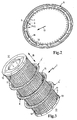
- Fig. 2 a perspective view of running as a separate item seal after Fig. 1 with details of its support ring and its formed as teeth securing edges;
- Fig. 3 a perspective view of the interchangeable filter cartridge after Fig. 1 with details of its folded filter body and the axially guided between the folds seal after Fig. 2 ;
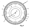
- Fig. 4 a schematic end view of another embodiment with radially protruding lugs of the end plate to form longitudinal stops
- Fig. 4a shows an alternative of a filter cartridge with a housing seal
- FIG. 4b shows a detailed representation of the in FIG. 4a shown seal carrier.
- Fig. 1 shows a schematic longitudinal sectional view of a filter for motor vehicles or industrial engines.
- an oil filter for the lubricating oil circuit of an automotive engine is provided. It may also be useful, for example, a hydraulic oil circuit and a fuel, water, coolant or air filter of motor vehicles or industrial engines another oil filter.
- the filter comprises a to a central axis 21 substantially rotationally symmetrical filter housing 3 and held in the filter housing 3, interchangeable filter cartridge 1.
- the filter housing 3 For removal or for insertion of the interchangeable filter cartridge 1, the filter housing 3 along a transverse or perpendicular to the central axis 21 lying separating surface 2 divisible.
- the filter housing 3 a lower housing part 4, which is fixedly connected to the engine or its oil circuit.
- Another housing part 5 of the filter housing 3 forms a lid which closes the interior of the lower housing part 4, and which is releasably connected in the region of the separating surface 2 with the lower housing part 4.
- the filter insert 1 extends in a direction parallel to the central axis 21 extending axial direction 18 and is designed substantially cylindrical. In the assembled state of the filter insert 1 is axially parallel to the also substantially cylindrical filter housing 3 in its closed interior. Axially parallel to the central axis 21, a schematically indicated, grid-like central tube 24 is provided, which centers and supports the filter cartridge 1.
- the filter cartridge 1 has a substantially cylindrical, in Fig. 3 filter body 19 shown in more detail from filter paper, at the two ends lying in the axial direction 18 12, 13 each have an end plate 10 is attached flow-tight. Between the two end plates 10 of the filter body 19 is encompassed by an annular seal 6.
- the seal 6 comprises a circumferential around the filter insert 1 support ring 7 with a relation to a radial direction 17 on the outside, also circumferential sealing ring 8.
- the elastic sealing ring 8 is located in a groove 27th of the housing 3, which rotates in the parting surface 2.
- the circumferential groove 27 is formed by a peripheral wall 28 and an end face 30 of the lower housing part 4 and by a further end face 29 of the upper housing part 5.
- the elastic sealing ring 8 is sealingly clamped to the two end faces 29, 30 at.
- the support ring 7 presses the sealing ring 8 in the radial direction 17 against the peripheral wall 28, whereby a sealing contact is ensured even in the radial direction 28. From the combination of axial and radial contact pressure of the sealing ring 8 results in an effective sealing of the two housing parts 4,5 within the separation surface 2 against each other. It may also be expedient to provide a sealing pressing only in the radial direction 17 or the axial direction 18.
- the interior of the filter housing 3 is divided by the filter element 1 in a radially outer annular space to form a raw side 22 and in a radially inner, approximately cylindrical space to form a clean side 23.
- the housing part 4 has at least one schematically indicated opening 25, through which the medium to be filtered - in this case oil - flows into the raw side 22. From there, the medium to be filtered flows counter to the radial direction 17 through the filter body 19, wherein the two axial end plates 10 prevent axial outflow.
- the filtered after passing through the filter body 19 and flowed into the clean side 23 medium occurs in the purified state through a central opening 26 of the filter housing 3 from.
- the sealing ring 6 and the sealing ring 8 comprehensive seal 6 of the two housing parts 4, 5 is held on the filter element 1 in a manner described in more detail below relative to the axial direction 18 slidably and captively on the filter element 1. If replacement of the filter cartridge 1 is required during maintenance work, the housing part 5 acting as cover is separated from the housing part 4, after which the filter cartridge 1 can be removed from the housing 3 or from the housing part 4 remaining on the motor. Due to the captive mounting of the seal 6 on the filter element 1, this is taken together with the filter cartridge 1 and disposed of. Reuse of the used seal 6 is avoided. A new, similar filter element 1 can then be inserted into the lower housing part 4, wherein at the same time the captive held new seal 6 is at least roughly shifted in its intended installation position in the axial direction 18.
- the axial displaceability of the seal 6 with respect to the filter cartridge 1 allows a fine positioning of the seal 6 relative to the groove 27 regardless of a movement of the filter cartridge 1.
- the captive holder on the filter element 1 ensures that the seal 6 in the final assembly of the filter housing 3 and in the connection of the two housing parts 4, 5 is not forgotten each other.
- the filter body 19 is also formed with its two end plates 10 relative to a plane perpendicular to the axial direction 18 center plane 20 mirror-symmetrical. This makes it possible to introduce the mirror-symmetrically designed filter element 1 arbitrarily with one of its two ends 12, 13 first in the housing part 5, in which case the seal 6 can be moved freely in the axial direction 18 to its mounting position in the separation surface 2.
- the comprehensive the support ring 7 and the sealing ring 8 seal 6 after Fig. 1 is in perspective view in Fig. 2 shown.
- the support ring 7 is substantially planar and made of a rigid compared to the rubbery elastic sealing ring 8 plastic.
- In connection with the planar design of the support ring 7 is at least in the radial direction 17 substantially rigid insofar as it acts in the radial direction 17, in connection with Fig. 1 described contact force can exert on the sealing ring 8 against the peripheral wall 28.
- the support ring 7 has arranged distributed over the circumference, designed as elongated holes openings 16 which an axial, undisturbed by the support ring 7 flow through the raw side 22 (FIGS. Fig. 1 ) in the filter housing 3 allow.
- the rubber-elastic sealing ring 8 encloses with an approximately U-shaped cross-section circumferentially a radially outer edge of the support ring 7. This is a positive attachment of the sealing ring 8 on the support ring. 7 given. Additionally or alternatively, the sealing ring 8 can also be glued to the support ring 7, sprayed on, vulcanized or applied fastened in another way.
- the encircling support ring 7 is provided on the inside with at least one securing edge 9 relative to the radial direction 17.
- the in Fig. 3 shown filter element 1 has at its two located in the axial direction 18 ends 12, 13 depending on at least one end stop 11 for the at least one securing edge 9 (Fig. Fig. 2 ) on. This allows the seal 6 after Fig. 2 Although displaced in the axial direction 18 on the filter body 19, but not be deducted from the filter body 19.
- Fig. 2 has the support ring 7 against the radial direction 17 inwardly projecting teeth 15 which are distributed uniformly over the circumference.
- teeth 15 By the teeth 15, a corresponding number of securing edges 9 is formed.
- the filter paper of the filter cartridge 1 is folded and cylindrically shaped to the filter body 19 that a number of folds 14 in the axial direction 18 extends.
- the teeth 15 between the axially extending folds 14, so that the in Fig. 3 represented seal 6 from its exemplary central position in the axial direction 18 in any, designated by 6 ', dashed axial positions can be moved.
- the two end disks 10 fastened to the filter body 19 at the axial ends 12, 13 have an outer diameter which essentially corresponds to the outer diameter of the folded filter body 19.
- the end plates 10 extending in the axial direction 18 the end plates 10 thereby form end stops 11 for acting as securing edges 9, between the folds 14 cross-teeth 15.
- the seal 6 can not in the episode on the end plates 10 are also deducted from the filter body 19.
- the folds 14 and the teeth 15 are each distributed uniformly over the circumference.
- the number of folds 14 and the teeth 15 is in the illustrated embodiment such that between each pair of folds 14 each a tooth 15 engages. It may also be appropriate to have a different number of folds 14 and teeth 15, the number of folds 14 advantageously being an integer multiple of the number of teeth 15.
- the rotationally symmetrical and in particular cylindrical shape of the filter cartridge 1 and the circular ring shape of the seal 6 according to Fig. 2 can also be a different, for example elliptical or rectangular cross-sectional shape appropriate.
- the fold-shaped filter body 19 after Fig. 3 can also be a smooth, for example, wound filter body appropriate, in which case the End stops 11 in the radial direction 17 protrude beyond the peripheral contour of the filter body 19.
- Such an embodiment is exemplary in a schematic end view in Fig. 4 shown.
- Both end plates 10 are identical and have evenly distributed over its circumference, in the radial direction 17 on the outer contour of the filter body 19 not shown protruding lugs 31.
- the seal 6 is comparable to the embodiment according to Fig. 2 with a openings 16 having support ring 7 and a radially outer circumferential sealing ring 8 executed.
- the support ring 7 has no radially inner teeth 15 (FIG. Fig. 2 ), but is limited relative to the radial direction 17 inwardly by a circular peripheral edge 32.
- the protruding in the radial direction 17 lugs 31 of the end plates 10 have a radially outer dimension which is greater than the inner diameter of the circular inner edge 32.
- the securing edge 9 of the support ring 7 is formed by the circular inner edge 32, which in the radial direction 17 of the noses 31 is overlapped.
- the inner edge 32 has a radial clearance with respect to the outer contour of the filter body 19, so that the seal 6 is comparable to the representation according to FIG Fig. 3 in the axial direction 18 indicated there is freely displaceable.
- the noses 31 formed as end stops 11 hold the seal 6 on the filter insert 1 in the axial direction 18 captive on the filter insert 1 firmly.
- FIG. 4a is an alternative of a seal carrier, shown in a detail sketch.
- a filter insert 20 is provided with two end plates 26, 27.
- the end plates have stop webs 33, 34, which limit the axial mobility of a sleeve.
- the sleeve 21 does not engage in folds of the zigzag-folded filter insert 20, but can be moved to the folds.
- It is equipped with carrier webs 22, 23, on which each elastic webs 25, a sealing ring 24 as in FIG. 4b is shown attached.
- the sealing ring has a shape suitable for sealing the housing parts 30, 31.
- On the housing part 31 is a groove in which a scraper ring 32 is arranged, this has the task to prevent the opening or closing of the two housing parts leakage of liquid from the housing.
- the wiper ring assumes no sealing function and is therefore not subject to wear.
Landscapes
- Chemical & Material Sciences (AREA)
- Chemical Kinetics & Catalysis (AREA)
- Lubrication Details And Ventilation Of Internal Combustion Engines (AREA)
- Filtration Of Liquid (AREA)
- Harvester Elements (AREA)
- Cleaning And Drying Hair (AREA)
- Cell Separators (AREA)
Claims (12)
- Insert de filtre (1), prévu comme insert échangeable dans un filtre, notamment dans un filtre à huile, filtre à carburant ou filtre analogue d'un moteur à combustion interne, le filtre comprenant un boîtier de filtre (3) divisible le long d'une surface de séparation (2) et l'insert de filtre (1) échangeable s'étendant dans un sens axial (18), et deux parties de boîtier (4, 5) du boîtier de filtre (3) étant étanchées l'une par rapport à l'autre le long de la surface de séparation (2) au moyen d'un joint d'étanchéité (6), caractérisé en ce que le joint d'étanchéité (6) peut être déplacé sur l'insert de filtre (1) en sens axial (18) et est maintenu de sorte à ne pas pouvoir être perdu.
- Insert de filtre selon la revendication 1, caractérisé en ce que le joint d'étanchéité (6) comprend une bague porteuse (7) encerclant l'insert de filtre (1) et dotée d'une bague d'étanchéité, la bague porteuse circulaire (7) étant pourvue à l'intérieur, considéré dans un sens radial (17), d'au moins une arête de sécurité (9), et l'insert de filtre (1) présentant au niveau de ses deux extrémités (12, 13) situées en sens axial (18) respectivement une butée d'extrémité (11) réalisée notamment en tant que plaque d'extrémité (10) pour l'arête de sécurité (9).
- Insert de filtre selon la revendication 2, caractérisé en ce que l'insert de filtre (1) comprend un corps de filtre (19) notamment en papier filtre avec des plis (14) s'étendant en sens axial (18), et en ce que la bague porteuse (7) du joint d'étanchéité (6) présente en sens radial des dents intérieures (15) afin de former les arêtes de sécurité (9), les dents (15) étant en prise entre les plis (14).
- Insert de filtre selon la revendication 3, caractérisé en ce que le nombre de plis (14) est identique au nombre de dents (15).
- Insert de filtre selon la revendication 2, caractérisé en ce que la plaque d'extrémité (10) présente, afin de former la butée d'extrémité (11), au moins un ergot (31) en saillie en sens radial (17) qui chevauche en sens radial (17) l'arête de sécurité (9) de la bague porteuse (7), arête qui est notamment réalisée en tant qu'arête intérieure (32) en forme de cercle.
- Insert de filtre selon l'une des revendications 2 à 5, caractérisé en ce que la bague porteuse circulaire (7) est pourvue d'orifices (16) faisant passer le flux.
- Insert de filtre selon la revendication 1, caractérisé en ce qu'une douille (21) mobile en sens axial soit prévue au niveau de l'insert de filtre (20) et en ce que cette douille présente au moins deux nervures porteuses (22, 23) auxquelles est fixé le joint d'étanchéité (24).
- Insert de filtre selon la revendication 7, caractérisé en ce que le joint d'étanchéité (24) est relié respectivement à la nervure porteuse (22, 23) par l'intermédiaire d'une nervure élastique (25).
- Insert de filtre selon la revendication 7, caractérisé en ce que des nervures de butée (33, 34) évitant que la douille ne soit perdue sont prévues au niveau des plaques d'extrémité (26, 27).
- Insert de filtre selon la revendication 7, caractérisé en ce que les deux parties du boîtier (30, 31) sont étanchées par le joint d'étanchéité (24) et que, de plus, une bague racleuse (32) se trouve entre les deux parties du boîtier (30, 31).
- Insert de filtre selon l'une des revendications 2 à 6, caractérisé en ce que la bague porteuse circulaire, notamment plane, est essentiellement rigide, au moins en sens radial (17).
- Insert de filtre selon l'une des revendications 1 à 7, caractérisé en ce que le corps de filtre (19), notamment avec ses plaques d'extrémité (10), est axialement symétrique à un plan médian (20) disposé verticalement au sens axial (18).
Applications Claiming Priority (2)
| Application Number | Priority Date | Filing Date | Title |
|---|---|---|---|
| DE202006018335U DE202006018335U1 (de) | 2006-12-04 | 2006-12-04 | Auswechselbarer Filtereinsatz |
| PCT/EP2007/062980 WO2008068182A1 (fr) | 2006-12-04 | 2007-11-29 | Garniture de filtre remplaçable |
Publications (2)
| Publication Number | Publication Date |
|---|---|
| EP2107928A1 EP2107928A1 (fr) | 2009-10-14 |
| EP2107928B1 true EP2107928B1 (fr) | 2010-05-12 |
Family
ID=39145321
Family Applications (1)
| Application Number | Title | Priority Date | Filing Date |
|---|---|---|---|
| EP07847497A Active EP2107928B1 (fr) | 2006-12-04 | 2007-11-29 | Garniture de filtre remplaçable |
Country Status (8)
| Country | Link |
|---|---|
| US (1) | US8501002B2 (fr) |
| EP (1) | EP2107928B1 (fr) |
| JP (1) | JP4865867B2 (fr) |
| KR (1) | KR101580334B1 (fr) |
| CN (1) | CN101547727B (fr) |
| AT (1) | ATE467450T1 (fr) |
| DE (2) | DE202006018335U1 (fr) |
| WO (1) | WO2008068182A1 (fr) |
Cited By (4)
| Publication number | Priority date | Publication date | Assignee | Title |
|---|---|---|---|---|
| US8272516B2 (en) | 2007-11-19 | 2012-09-25 | Caterpillar Inc. | Fluid filter system |
| US8460545B2 (en) | 2007-10-17 | 2013-06-11 | Caterpillar Inc. | Canister filter system with drain that cooperates with filter element |
| US8501003B2 (en) | 2007-10-17 | 2013-08-06 | Caterpillar Inc. | Canister filter system with drain that cooperates with filter element |
| DE102023121707A1 (de) | 2023-08-14 | 2025-02-20 | Mann+Hummel Gmbh | Filtersystem und Filterelement für ein Fluid |
Families Citing this family (17)
| Publication number | Priority date | Publication date | Assignee | Title |
|---|---|---|---|---|
| DE102007046209A1 (de) | 2007-09-27 | 2009-04-09 | Hydac Filtertechnik Gmbh | Filtervorrichtung und Filterelement |
| DE102011106502A1 (de) | 2011-06-15 | 2012-12-20 | Mann + Hummel Gmbh | Filterelement und Gehäuse für ein Filterelement |
| DE102012006226A1 (de) | 2012-03-27 | 2013-10-02 | Hydac Filtertechnik Gmbh | Anordnung zur Bildung einer Abdichtung |
| CN103352851B (zh) * | 2013-06-09 | 2015-11-25 | 浙江飞越机电有限公司 | 真空泵用油雾过滤器 |
| DE102013020502B4 (de) | 2013-12-11 | 2016-12-15 | Mann + Hummel Gmbh | Filtersystem und Filterelement mit Kupplungsvorrichtung und Dichtungsvorrichtung |
| DE202013011841U1 (de) | 2013-12-11 | 2015-03-18 | Mann + Hummel Gmbh | Filtersystem und Filterelement mit Kupplungsvorrichtung und Dichtungsvorrichtung |
| CN105457366B (zh) * | 2015-12-22 | 2017-11-24 | 湖州恒鑫过滤科技有限公司 | 一种大通量多芯过滤器 |
| DE102016009844A1 (de) * | 2016-08-16 | 2018-02-22 | Mann + Hummel Gmbh | Filterelementanordnung mit Dichtelement und Filtersystem |
| CN106368766A (zh) * | 2016-09-30 | 2017-02-01 | 芜湖豫新世通汽车空调有限公司 | 汽车机油滤芯 |
| CN106150595B (zh) * | 2016-09-30 | 2019-01-15 | 芜湖豫新世通汽车空调有限公司 | 汽车机油滤芯 |
| JP2018143986A (ja) * | 2017-03-07 | 2018-09-20 | 京三電機株式会社 | フィルタ装置 |
| SE540765C2 (en) * | 2017-03-20 | 2018-11-06 | Scania Cv Ab | Filter arrangement comprising a housing and a filter unit, and a filter unit comprising a sealing |
| DE102018122967A1 (de) * | 2018-09-19 | 2020-03-19 | Hengst Se | Dichtungsträger, Filtereinsatz und Filter |
| US11707703B2 (en) * | 2020-04-27 | 2023-07-25 | Caterpillar Inc. | Filter element integrated seal profile |
| US11541334B2 (en) * | 2020-07-01 | 2023-01-03 | Caterpillar Inc. | Integral filter endcap, mold, and seal |
| DE102020128911A1 (de) | 2020-11-03 | 2022-05-05 | Mann+Hummel Gmbh | Filtersystem und Filterelement |
| US20250001333A1 (en) * | 2023-06-30 | 2025-01-02 | Caterpillar Inc. | Filter, filter component, and filter connector system having interlocking tabs and retention elements |
Family Cites Families (28)
| Publication number | Priority date | Publication date | Assignee | Title |
|---|---|---|---|---|
| US1682655A (en) * | 1925-09-26 | 1928-08-28 | Campbell Hausfeld Company | Oil strainer |
| US2988227A (en) * | 1958-03-03 | 1961-06-13 | Harold H Harms | Pleated filter |
| US3042079A (en) * | 1958-04-15 | 1962-07-03 | American District Telegraph Co | Adjustable vent |
| DE1118758B (de) * | 1959-11-05 | 1961-12-07 | Fr August Neidig Soehne Maschi | Fluessigkeitsfilter mit zylindrischem Filtereinsatz |
| US3856683A (en) * | 1972-12-15 | 1974-12-24 | E Parr | Dual flow fluid filter |
| US4342375A (en) * | 1975-07-11 | 1982-08-03 | Oil-Rite Corporation | Porous rod metering valve |
| US4062424A (en) * | 1975-07-11 | 1977-12-13 | Oil-Rite Corporation | Oiler assembly |
| US4547950A (en) | 1984-05-29 | 1985-10-22 | Honeywell Inc. | Method of spacing the folds of a folded filter media |
| US4721563A (en) * | 1986-09-11 | 1988-01-26 | Rosaen Borje O | Fluid filtering device |
| DE3641348A1 (de) * | 1986-12-03 | 1988-06-16 | Bosch Gmbh Robert | Fluessigkeitsfilter, insbesondere fuer kraftstoffe |
| US5211846A (en) | 1990-07-30 | 1993-05-18 | Pleatco Electronic & Filter Corp. | Replacement filter cartridge assembly |
| DE59208594D1 (de) * | 1991-03-28 | 1997-07-10 | Knecht Filterwerke Gmbh | Flüssigkeitsfilter |
| US5548893A (en) * | 1995-03-20 | 1996-08-27 | Koelfgen; Douglas F. | Spin-on oil filter replacement element |
| FI98990C (fi) * | 1995-10-27 | 1997-09-25 | Parker Hannifinn Oy | Suodatin |
| GB2306342B (en) * | 1995-11-02 | 2000-03-01 | Pall Corp | Filter assemblies and end caps for filter assemblies |
| US5685985A (en) * | 1995-12-20 | 1997-11-11 | Baldwin Filters, Inc. | Environmentally friendly filter cartridge |
| JP3680396B2 (ja) * | 1995-12-27 | 2005-08-10 | 株式会社デンソー | エレメント交換型フィルタ |
| US5860796A (en) | 1996-08-07 | 1999-01-19 | Parker-Hannifin Corporation | Fuel pump assembly and filter element therefor |
| DE19707132A1 (de) * | 1997-02-22 | 1998-08-27 | Mann & Hummel Filter | Filter |
| FR2762229B1 (fr) * | 1997-04-18 | 1999-07-16 | Fleetguard | Filtre et cartouche de filtrage a butee peripherique pour le filtrage de liquides circulant dans un moteur ou dans un equipement hydraulique |
| DE29917563U1 (de) * | 1999-09-09 | 2001-02-01 | Ing. Walter Hengst GmbH & Co KG, 48147 Münster | Fluidfilter mit gehäusefestem Ablassdom |
| US6478959B1 (en) * | 2000-11-14 | 2002-11-12 | Nelson Industries, Inc. | Self-fixturing filter |
| KR100583567B1 (ko) | 2000-12-13 | 2006-05-26 | 엘지전자 주식회사 | 진공청소기의 필터 착탈확인 구조 |
| US6571962B2 (en) * | 2001-04-30 | 2003-06-03 | Fleetguard, Inc. | Cartridge filter element with housing seal retainer |
| US6740234B1 (en) * | 2002-03-05 | 2004-05-25 | Stanadyne Corporation | Key track system |
| US7097684B2 (en) * | 2002-12-12 | 2006-08-29 | Aaf-Mcquay, Inc. | Method of forming combined pleated scrim and filter media materials and product of same |
| DE102004005211B4 (de) * | 2004-02-03 | 2013-03-21 | Mahle Filtersysteme Gmbh | Ringförmiges Filterelement und zugehöriges Herstellungsverfahren |
| DE102005007018A1 (de) * | 2005-02-15 | 2006-08-24 | Mann + Hummel Gmbh | Flüssigkeitsfilter |
-
2006
- 2006-12-04 DE DE202006018335U patent/DE202006018335U1/de not_active Expired - Lifetime
-
2007
- 2007-11-29 JP JP2009538709A patent/JP4865867B2/ja not_active Expired - Fee Related
- 2007-11-29 KR KR1020097011390A patent/KR101580334B1/ko active Active
- 2007-11-29 AT AT07847497T patent/ATE467450T1/de active
- 2007-11-29 WO PCT/EP2007/062980 patent/WO2008068182A1/fr not_active Ceased
- 2007-11-29 EP EP07847497A patent/EP2107928B1/fr active Active
- 2007-11-29 US US12/516,059 patent/US8501002B2/en not_active Expired - Fee Related
- 2007-11-29 DE DE502007003807T patent/DE502007003807D1/de active Active
- 2007-11-29 CN CN2007800447032A patent/CN101547727B/zh active Active
Cited By (8)
| Publication number | Priority date | Publication date | Assignee | Title |
|---|---|---|---|---|
| US8460545B2 (en) | 2007-10-17 | 2013-06-11 | Caterpillar Inc. | Canister filter system with drain that cooperates with filter element |
| US8501003B2 (en) | 2007-10-17 | 2013-08-06 | Caterpillar Inc. | Canister filter system with drain that cooperates with filter element |
| US8535529B2 (en) | 2007-10-17 | 2013-09-17 | Caterpillar Inc. | Canister filter system with drain that cooperates with filter element |
| US9511314B2 (en) | 2007-10-17 | 2016-12-06 | Caterpillar Inc. | Canister filter system with drain that cooperates with filter element |
| US8272516B2 (en) | 2007-11-19 | 2012-09-25 | Caterpillar Inc. | Fluid filter system |
| US8540080B2 (en) | 2007-11-19 | 2013-09-24 | Caterpillar Inc. | Fluid filter system |
| US9089795B2 (en) | 2007-11-19 | 2015-07-28 | Caterpillar Inc. | Fluid filter system |
| DE102023121707A1 (de) | 2023-08-14 | 2025-02-20 | Mann+Hummel Gmbh | Filtersystem und Filterelement für ein Fluid |
Also Published As
| Publication number | Publication date |
|---|---|
| CN101547727B (zh) | 2011-12-14 |
| JP2010511823A (ja) | 2010-04-15 |
| WO2008068182A1 (fr) | 2008-06-12 |
| KR20090087465A (ko) | 2009-08-17 |
| JP4865867B2 (ja) | 2012-02-01 |
| ATE467450T1 (de) | 2010-05-15 |
| DE202006018335U1 (de) | 2008-04-17 |
| US8501002B2 (en) | 2013-08-06 |
| US20100170842A1 (en) | 2010-07-08 |
| CN101547727A (zh) | 2009-09-30 |
| EP2107928A1 (fr) | 2009-10-14 |
| KR101580334B1 (ko) | 2015-12-28 |
| DE502007003807D1 (de) | 2010-06-24 |
Similar Documents
| Publication | Publication Date | Title |
|---|---|---|
| EP2107928B1 (fr) | Garniture de filtre remplaçable | |
| EP2099544B1 (fr) | Filtre à huile, séparateur d'huile et élément filtrant pour celui-ci | |
| EP1154831B1 (fr) | Filtre a liquide comprenant un element central demontable et un element de maintien supplementaire | |
| DE102014006853B4 (de) | Hohlfilterelement, Filtergehäuse und Filter | |
| DE112017000592B4 (de) | Filterelement eines Flüssigkeitsfilters und dessen Verwendung in einem Flüssigkeitsfilter | |
| DE202017006783U1 (de) | Rundfilterelement, insbesondere zur Gasfiltration | |
| DE102012209242A1 (de) | Filtereinrichtung | |
| DE102010064030A1 (de) | Luftfilterelement | |
| DE29915844U1 (de) | Filter mit Ventil-Kombinationsbauteil | |
| EP2808071B1 (fr) | Dispositif de filtre, en particulier pour un véhicule automobile | |
| DE102006038100A1 (de) | Filterelement, insbesondere zur Filtrierung von Flüssigkeiten oder Gasen | |
| DE102007057380B4 (de) | Filter mit einem auswechselbaren Filtereinsatz | |
| DE102006029107A1 (de) | Membran für die Steuerung von Flüssigkeitsströmen | |
| EP2502657A1 (fr) | Dispositif de filtre | |
| WO2024061494A1 (fr) | Système de filtre à gaz | |
| EP3727643A1 (fr) | Élément filtrant d'un filtre à liquide, élément de fermeture d'écoulement pour ouverture d'écoulement d'un boîtier de filtre, partie boîtier d'un boîtier de filtre et filtre | |
| DE102019217374A1 (de) | Filtereinrichtung, Filterwechselverfahren zum Filterwechsel eines in einer Filtereinrichtung angeordneten Filterelements sowie Filterelement für eine Filtereinrichtung | |
| EP2831472A1 (fr) | Système pour la constitution d'une étanchéité | |
| DE102017214718A1 (de) | Filtereinrichtung | |
| DE102023117938A1 (de) | Ablassverschlusselement für ein Filtersystem, Filterelement und Filtersystem | |
| DE102023117941A1 (de) | Filterelement, Ablassverschlusselement und Filtersystem | |
| DE102013011813B4 (de) | Filtereinrichtung und Filterelement | |
| DE102016013952A1 (de) | Filterelement, Filtervorrichtung, Filtergehäuse und Dichtung | |
| DE102016218368A1 (de) | Filtereinrichtung | |
| DE102014009583A1 (de) | Stützrohr für ein Filterelement und Werkzeug zur Herstellung eines Stützrohrs |
Legal Events
| Date | Code | Title | Description |
|---|---|---|---|
| PUAI | Public reference made under article 153(3) epc to a published international application that has entered the european phase |
Free format text: ORIGINAL CODE: 0009012 |
|
| 17P | Request for examination filed |
Effective date: 20090506 |
|
| AK | Designated contracting states |
Kind code of ref document: A1 Designated state(s): AT BE BG CH CY CZ DE DK EE ES FI FR GB GR HU IE IS IT LI LT LU LV MC MT NL PL PT RO SE SI SK TR |
|
| GRAP | Despatch of communication of intention to grant a patent |
Free format text: ORIGINAL CODE: EPIDOSNIGR1 |
|
| DAX | Request for extension of the european patent (deleted) | ||
| GRAS | Grant fee paid |
Free format text: ORIGINAL CODE: EPIDOSNIGR3 |
|
| GRAA | (expected) grant |
Free format text: ORIGINAL CODE: 0009210 |
|
| AK | Designated contracting states |
Kind code of ref document: B1 Designated state(s): AT BE BG CH CY CZ DE DK EE ES FI FR GB GR HU IE IS IT LI LT LU LV MC MT NL PL PT RO SE SI SK TR |
|
| REG | Reference to a national code |
Ref country code: GB Ref legal event code: FG4D Free format text: NOT ENGLISH |
|
| REG | Reference to a national code |
Ref country code: CH Ref legal event code: EP |
|
| REG | Reference to a national code |
Ref country code: IE Ref legal event code: FG4D Free format text: LANGUAGE OF EP DOCUMENT: GERMAN |
|
| REF | Corresponds to: |
Ref document number: 502007003807 Country of ref document: DE Date of ref document: 20100624 Kind code of ref document: P |
|
| REG | Reference to a national code |
Ref country code: NL Ref legal event code: VDEP Effective date: 20100512 |
|
| LTIE | Lt: invalidation of european patent or patent extension |
Effective date: 20100512 |
|
| PG25 | Lapsed in a contracting state [announced via postgrant information from national office to epo] |
Ref country code: SE Free format text: LAPSE BECAUSE OF FAILURE TO SUBMIT A TRANSLATION OF THE DESCRIPTION OR TO PAY THE FEE WITHIN THE PRESCRIBED TIME-LIMIT Effective date: 20100512 Ref country code: NL Free format text: LAPSE BECAUSE OF FAILURE TO SUBMIT A TRANSLATION OF THE DESCRIPTION OR TO PAY THE FEE WITHIN THE PRESCRIBED TIME-LIMIT Effective date: 20100512 Ref country code: LT Free format text: LAPSE BECAUSE OF FAILURE TO SUBMIT A TRANSLATION OF THE DESCRIPTION OR TO PAY THE FEE WITHIN THE PRESCRIBED TIME-LIMIT Effective date: 20100512 Ref country code: ES Free format text: LAPSE BECAUSE OF FAILURE TO SUBMIT A TRANSLATION OF THE DESCRIPTION OR TO PAY THE FEE WITHIN THE PRESCRIBED TIME-LIMIT Effective date: 20100823 |
|
| PG25 | Lapsed in a contracting state [announced via postgrant information from national office to epo] |
Ref country code: FI Free format text: LAPSE BECAUSE OF FAILURE TO SUBMIT A TRANSLATION OF THE DESCRIPTION OR TO PAY THE FEE WITHIN THE PRESCRIBED TIME-LIMIT Effective date: 20100512 Ref country code: IS Free format text: LAPSE BECAUSE OF FAILURE TO SUBMIT A TRANSLATION OF THE DESCRIPTION OR TO PAY THE FEE WITHIN THE PRESCRIBED TIME-LIMIT Effective date: 20100912 Ref country code: LV Free format text: LAPSE BECAUSE OF FAILURE TO SUBMIT A TRANSLATION OF THE DESCRIPTION OR TO PAY THE FEE WITHIN THE PRESCRIBED TIME-LIMIT Effective date: 20100512 Ref country code: SI Free format text: LAPSE BECAUSE OF FAILURE TO SUBMIT A TRANSLATION OF THE DESCRIPTION OR TO PAY THE FEE WITHIN THE PRESCRIBED TIME-LIMIT Effective date: 20100512 |
|
| REG | Reference to a national code |
Ref country code: IE Ref legal event code: FD4D |
|
| PG25 | Lapsed in a contracting state [announced via postgrant information from national office to epo] |
Ref country code: CY Free format text: LAPSE BECAUSE OF FAILURE TO SUBMIT A TRANSLATION OF THE DESCRIPTION OR TO PAY THE FEE WITHIN THE PRESCRIBED TIME-LIMIT Effective date: 20100616 Ref country code: PL Free format text: LAPSE BECAUSE OF FAILURE TO SUBMIT A TRANSLATION OF THE DESCRIPTION OR TO PAY THE FEE WITHIN THE PRESCRIBED TIME-LIMIT Effective date: 20100512 |
|
| PG25 | Lapsed in a contracting state [announced via postgrant information from national office to epo] |
Ref country code: IE Free format text: LAPSE BECAUSE OF FAILURE TO SUBMIT A TRANSLATION OF THE DESCRIPTION OR TO PAY THE FEE WITHIN THE PRESCRIBED TIME-LIMIT Effective date: 20100512 Ref country code: DK Free format text: LAPSE BECAUSE OF FAILURE TO SUBMIT A TRANSLATION OF THE DESCRIPTION OR TO PAY THE FEE WITHIN THE PRESCRIBED TIME-LIMIT Effective date: 20100512 Ref country code: PT Free format text: LAPSE BECAUSE OF FAILURE TO SUBMIT A TRANSLATION OF THE DESCRIPTION OR TO PAY THE FEE WITHIN THE PRESCRIBED TIME-LIMIT Effective date: 20100913 Ref country code: EE Free format text: LAPSE BECAUSE OF FAILURE TO SUBMIT A TRANSLATION OF THE DESCRIPTION OR TO PAY THE FEE WITHIN THE PRESCRIBED TIME-LIMIT Effective date: 20100512 |
|
| PG25 | Lapsed in a contracting state [announced via postgrant information from national office to epo] |
Ref country code: RO Free format text: LAPSE BECAUSE OF FAILURE TO SUBMIT A TRANSLATION OF THE DESCRIPTION OR TO PAY THE FEE WITHIN THE PRESCRIBED TIME-LIMIT Effective date: 20100512 Ref country code: SK Free format text: LAPSE BECAUSE OF FAILURE TO SUBMIT A TRANSLATION OF THE DESCRIPTION OR TO PAY THE FEE WITHIN THE PRESCRIBED TIME-LIMIT Effective date: 20100512 Ref country code: CZ Free format text: LAPSE BECAUSE OF FAILURE TO SUBMIT A TRANSLATION OF THE DESCRIPTION OR TO PAY THE FEE WITHIN THE PRESCRIBED TIME-LIMIT Effective date: 20100512 |
|
| PLBE | No opposition filed within time limit |
Free format text: ORIGINAL CODE: 0009261 |
|
| STAA | Information on the status of an ep patent application or granted ep patent |
Free format text: STATUS: NO OPPOSITION FILED WITHIN TIME LIMIT |
|
| 26N | No opposition filed |
Effective date: 20110215 |
|
| BERE | Be: lapsed |
Owner name: MANN+HUMMEL G.M.B.H. Effective date: 20101130 |
|
| PG25 | Lapsed in a contracting state [announced via postgrant information from national office to epo] |
Ref country code: GR Free format text: LAPSE BECAUSE OF FAILURE TO SUBMIT A TRANSLATION OF THE DESCRIPTION OR TO PAY THE FEE WITHIN THE PRESCRIBED TIME-LIMIT Effective date: 20100813 |
|
| REG | Reference to a national code |
Ref country code: DE Ref legal event code: R097 Ref document number: 502007003807 Country of ref document: DE Effective date: 20110214 |
|
| PG25 | Lapsed in a contracting state [announced via postgrant information from national office to epo] |
Ref country code: MC Free format text: LAPSE BECAUSE OF NON-PAYMENT OF DUE FEES Effective date: 20101130 |
|
| PG25 | Lapsed in a contracting state [announced via postgrant information from national office to epo] |
Ref country code: BE Free format text: LAPSE BECAUSE OF NON-PAYMENT OF DUE FEES Effective date: 20101130 |
|
| PG25 | Lapsed in a contracting state [announced via postgrant information from national office to epo] |
Ref country code: MT Free format text: LAPSE BECAUSE OF FAILURE TO SUBMIT A TRANSLATION OF THE DESCRIPTION OR TO PAY THE FEE WITHIN THE PRESCRIBED TIME-LIMIT Effective date: 20100512 Ref country code: IT Free format text: LAPSE BECAUSE OF NON-PAYMENT OF DUE FEES Effective date: 20101129 |
|
| REG | Reference to a national code |
Ref country code: CH Ref legal event code: PL |
|
| PG25 | Lapsed in a contracting state [announced via postgrant information from national office to epo] |
Ref country code: LI Free format text: LAPSE BECAUSE OF NON-PAYMENT OF DUE FEES Effective date: 20111130 Ref country code: CH Free format text: LAPSE BECAUSE OF NON-PAYMENT OF DUE FEES Effective date: 20111130 |
|
| PG25 | Lapsed in a contracting state [announced via postgrant information from national office to epo] |
Ref country code: HU Free format text: LAPSE BECAUSE OF FAILURE TO SUBMIT A TRANSLATION OF THE DESCRIPTION OR TO PAY THE FEE WITHIN THE PRESCRIBED TIME-LIMIT Effective date: 20101113 Ref country code: LU Free format text: LAPSE BECAUSE OF NON-PAYMENT OF DUE FEES Effective date: 20101129 Ref country code: BG Free format text: LAPSE BECAUSE OF FAILURE TO SUBMIT A TRANSLATION OF THE DESCRIPTION OR TO PAY THE FEE WITHIN THE PRESCRIBED TIME-LIMIT Effective date: 20100512 |
|
| PG25 | Lapsed in a contracting state [announced via postgrant information from national office to epo] |
Ref country code: TR Free format text: LAPSE BECAUSE OF FAILURE TO SUBMIT A TRANSLATION OF THE DESCRIPTION OR TO PAY THE FEE WITHIN THE PRESCRIBED TIME-LIMIT Effective date: 20100512 |
|
| PG25 | Lapsed in a contracting state [announced via postgrant information from national office to epo] |
Ref country code: BG Free format text: LAPSE BECAUSE OF FAILURE TO SUBMIT A TRANSLATION OF THE DESCRIPTION OR TO PAY THE FEE WITHIN THE PRESCRIBED TIME-LIMIT Effective date: 20100812 |
|
| REG | Reference to a national code |
Ref country code: AT Ref legal event code: MM01 Ref document number: 467450 Country of ref document: AT Kind code of ref document: T Effective date: 20121130 |
|
| PG25 | Lapsed in a contracting state [announced via postgrant information from national office to epo] |
Ref country code: AT Free format text: LAPSE BECAUSE OF NON-PAYMENT OF DUE FEES Effective date: 20121130 |
|
| REG | Reference to a national code |
Ref country code: FR Ref legal event code: PLFP Year of fee payment: 9 |
|
| REG | Reference to a national code |
Ref country code: FR Ref legal event code: PLFP Year of fee payment: 10 |
|
| REG | Reference to a national code |
Ref country code: FR Ref legal event code: PLFP Year of fee payment: 11 |
|
| REG | Reference to a national code |
Ref country code: DE Ref legal event code: R081 Ref document number: 502007003807 Country of ref document: DE Owner name: MANN+HUMMEL GMBH, DE Free format text: FORMER OWNER: MANN + HUMMEL GMBH, 71638 LUDWIGSBURG, DE |
|
| PGFP | Annual fee paid to national office [announced via postgrant information from national office to epo] |
Ref country code: DE Payment date: 20241121 Year of fee payment: 18 |
|
| PGFP | Annual fee paid to national office [announced via postgrant information from national office to epo] |
Ref country code: GB Payment date: 20241120 Year of fee payment: 18 |
|
| PGFP | Annual fee paid to national office [announced via postgrant information from national office to epo] |
Ref country code: FR Payment date: 20241128 Year of fee payment: 18 |
|
| PGFP | Annual fee paid to national office [announced via postgrant information from national office to epo] |
Ref country code: IT Payment date: 20241126 Year of fee payment: 18 |