EP2108285A1 - Couchette - Google Patents
Couchette Download PDFInfo
- Publication number
- EP2108285A1 EP2108285A1 EP09004309A EP09004309A EP2108285A1 EP 2108285 A1 EP2108285 A1 EP 2108285A1 EP 09004309 A EP09004309 A EP 09004309A EP 09004309 A EP09004309 A EP 09004309A EP 2108285 A1 EP2108285 A1 EP 2108285A1
- Authority
- EP
- European Patent Office
- Prior art keywords
- cradle
- frame
- connecting rods
- slats
- lounger according
- Prior art date
- Legal status (The legal status is an assumption and is not a legal conclusion. Google has not performed a legal analysis and makes no representation as to the accuracy of the status listed.)
- Granted
Links
Images


Classifications
-
- A—HUMAN NECESSITIES
- A47—FURNITURE; DOMESTIC ARTICLES OR APPLIANCES; COFFEE MILLS; SPICE MILLS; SUCTION CLEANERS IN GENERAL
- A47C—CHAIRS; SOFAS; BEDS
- A47C3/00—Chairs characterised by structural features; Chairs or stools with rotatable or vertically-adjustable seats
- A47C3/02—Rocking chairs
- A47C3/025—Rocking chairs with seat, or seat and back-rest unit, elastically mounted in a rigid frame
- A47C3/0255—Rocking chairs with seat, or seat and back-rest unit, elastically mounted in a rigid frame pivotally mounted in the base frame, e.g. swings
-
- A—HUMAN NECESSITIES
- A47—FURNITURE; DOMESTIC ARTICLES OR APPLIANCES; COFFEE MILLS; SPICE MILLS; SUCTION CLEANERS IN GENERAL
- A47C—CHAIRS; SOFAS; BEDS
- A47C3/00—Chairs characterised by structural features; Chairs or stools with rotatable or vertically-adjustable seats
- A47C3/02—Rocking chairs
- A47C3/025—Rocking chairs with seat, or seat and back-rest unit, elastically mounted in a rigid frame
- A47C3/0251—Rocking chairs with seat, or seat and back-rest unit, elastically mounted in a rigid frame driven by electric motors
Definitions
- the invention relates to a daybed with a lying on an upper deck surface Shamschale which is received on an associated frame and optionally in a lying or sitting position can be brought.
- the cradle is pivotally mounted about an axis on the associated frame and tiltable between two stop positions. In any intermediate positions there is no stable support, so that the cradle in these intermediate positions is not usable. Due to the pivotal mounting of the cradle and only a pivoting movement of the cradle is possible. A pendulum movement of the cradle against the frame is not provided. The known arrangements therefore prove to be not comfortable and versatile enough.
- the cradle is suspended by support members about its central longitudinal axis without tilting the manner of a swing on the frame, each in the longitudinal direction of the cradle staggered support elements are in opposite directions extendable or shortened.
- the frame may be formed as a free-standing block, which is provided in the region of its upper end with a support elements associated with the receiving elements, preferably designed as a winding shaft.
- the support elements may be mounted on different sides of the winding shaft, so that they are extended by pressing the winding shaft in pairs or shortened.
- a further advantageous measure may consist in that the support elements are designed as straps and the winding shaft is provided with the straps associated, circumferential grooves.
- winding shaft is formed as a hollow shaft which is rotatably supported on the one hand on the one hand and on the other hand connected to a tube motor mounted on the frame.
- the block may have two roof-shaped side parts, which are interconnected by trusses.
- advantageously plug or threaded connections can be provided, which is a tool-free installation allows.
- a further advantageous measure may consist in that the cradle consists of parallel lamellae, which are distanced from each other by spacers and connected to each other by dowel screws passing through the width, wherein the lamellae are expediently formed as a layer-glued wooden moldings.
- Main field of application of the present invention are multi-functional couches for the wellness and / or adventure area, wherein a lying and sitting function in addition to a swing function is given. Accordingly, the couches according to the invention are swing benches.
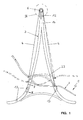
- the in the FIGS. 1 and 2 shown swing couch contains a cradle 1, the top of which forms an ergonomically shaped deck surface 2.
- the cradle 1 is suspended in its orientation relative to the horizontal adjustable pendulum on a gantry-shaped frame 3.
- the videschale 1 can from an in FIG. 1 indicated by solid lines seat position can be adjusted in a direction indicated by broken lines lying position and vice versa.
- the cradle 1 is tilt-free about its central longitudinal axis at several, here four arranged laterally, in pairs offset longitudinally staggered support elements 4 and hereby suspended in the manner of a swing on the frame 3.
- a statically determined three-way arrangement of two laterally and one centrally arranged support elements would be conceivable.
- the support elements 4 are movable. Expedient to find the formation of the support elements 4 straps use.
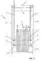
- the cradle 1 is, in the example shown as best off FIG. 2 can be seen, provided with four lateral, pairwise opposing trunnions 5, on each of which a support element 4 engages.
- the belts provided for the formation of the support elements 4 can be provided for this purpose with the respectively associated support pins 5 looping eyelets or loops.
- the frame 3 is, as already mentioned, formed as a free-standing block, which is provided in the region of its upper end with a supporting elements 4 associated receiving device. This is advantageously designed as a winding shaft 6, to which the front and rear support members 4 in the example shown in opposite directions wound up or from the front and rear support members 4 in the example shown in pairs are unwound.
- the paired here on each side of the cradle 1 provided support members 4 are secured with their upper ends to the winding shaft 6 that they wrap around them with opposite sense of rotation, so that upon rotation of the winding shaft 6 results in an opposite extension or shortening.
- the winding shaft 6 is provided with the support elements 4 associated, formed by circumferential grooves 7 winding tracks. This ensures that the straps forming the support elements 4 can form a proper winding.
- a connected to the winding shaft 6 sprocket can be provided for this purpose, which is actuated by means of a circulating chain of the cradle 1 from.
- the chain can be suitably formed as a so-called pearl necklace.
- the winding shaft 6 is appropriate, as from the Figures 3 and 4 can be seen, designed as a hollow shaft which is rotatably supported on the one hand on the frame 3 and which is connected at its other end with a tube motor 8 inserted into it, which is rotatably supported on the frame 3, as in FIG. 4 is indicated by an engaging in an associated, frame-side recess supporting pin 9, which has a polygonal cross-section for Ver too a rotation.
- the pivot bearing provided on the side facing away from the tubular motor can be accomplished with the aid of a bearing 10 inserted into the frame 4, into which a lateral bearing journal 11 of the winding shaft 6 engages.
- the tubular motor 8 or another to drive the winding shaft 6 associated motor is expediently associated with a power supply not shown here.
- a mounted on the frame 3 accessible from the cradle 1 from switch can be provided. Conveniently, however, provided a remote control, so that a stationary switch is unnecessary.
- the frame forming the frame 3 is, as best of FIG. 2 it can be seen from two side parts 3a, b, which are interconnected by trusses 12, 13.
- the side parts 3a, b each consist, as best of all FIG. 1 It can be seen from two roof-shaped legs spread apart, which are connected to each other in the region of its upper end and terminate in a common end piece 14 on which the winding shaft 6 is received.
- one of the winding shaft 6 adjacent, upper cross member 12 is provided, which is expediently designed to accomplish a high Wackel tone as a comparatively broad board.
- the upper traverse 12 forming board is suitably connected by means of a plug connection to the side parts 3a, b and the upper end pieces 14.
- bed fittings find use 15, which result in a bayonet-type connector.
- trusses 13 are provided, which are located below the cradle 1, so that their pendulum movements are not hindered by this.
- These lower trusses 13 are appropriate, as from the FIGS. 5 and 6 can be seen, formed as a hollow rods, which are penetrated by a threaded rod 16, the ends of which are screwed into associated, the frame side provided threaded dowel 17.
- the threaded rods 16 are arranged against rotation relative to the associated hollow rod.
- the threaded rods 16 are each provided with a transverse pin 18, which engages in an associated inner axial groove 19 of the associated hollow rod.
- the cradle can be designed as a one-piece molding.
- the cradle 1 as best of FIG. 2 it can be seen from a plurality of parallel juxtaposed slats 20, which are spaced apart by spacers 21 and by over the width of the cradle continuous, the spacer elements receiving connecting rods 22 are interconnected.
- the slats 20 are with each Connecting rod 22 associated, aligned holes provided.
- Two of said connecting rods 22 may be extended to form the lateral support pins 5 beyond the side edges of the cradle 1 addition, wherein at the ends flange-like termination buttons may be provided.
- the slats 20 are expediently made of wood. It can be advantageous layered wood use find that is permanently deformed, so that from FIG. 1 apparent, desirable, ergonomic shape.
- the seat 1 may be associated with side armrests 23. These are expediently also formed as a layer-glued wooden moldings.
- the armrests 23 are suitably penetrated in the region of their ends of the lateral support pin 5 and hereby attached to the cradle 1.
- the connecting rods 22 may be made of wood, plastic or metal. When expected high, on the cradle 1 coming weights, the connecting pin 22 associated with the support pins 5 can be made of metal to ensure the required load capacity. As a rule, however, connecting rods 22 made of hardwood etc. can be used. Appropriately, a backup of the connecting rods 22 is provided against lateral slipping. This can be done by an adhesive bond and / or locking pins and / or a screw connection.
- the connecting rods 22 associated with the upper and lower ends of the cradle 1 may be designed to provide lateral cohesion of the cradle 22 cradles as dowel screws passing through the cradle width, the ends of which are associated with threaded dowels provided in the outer fins 20 can be screwed.
- a screw head at one end and a threaded portion cooperating with a nut or a threaded dowel at the other end.
- a joining or plug connection can also be provided.
- FIG. 7 Such an embodiment is the FIG. 7 based.
- the in FIG. 7 shown connecting rod 22 engages with its ends in a respective associated blind bore 25 of the outer blades 22 of the Stanfordschale 1 forming lamellar frame.
- the inner fins 20 are provided with aligned with the blind holes 25 of the outer fins through holes 25 a.
- the engaging in the blind holes 25 and bores 25 a connecting rods 22 are suitably glued to the slats 20. Appropriately, the first assembly of the cradle 1 forming frame and then only the gluing takes place.
- blind holes 25 and through holes 25a are slightly oversized with respect to the diameter of the associated connecting rod 22, so that a circumferential gap to form a glue receiving space 26 results, as best seen FIG. 8 is apparent.
- the excess may be 3 to 4% of the diameter of the connecting rod 22. With a diameter of 14 mm, this results in an excess of 0.5 mm.
- FIG. 8 further shows, provided with at least one, preferably two diametrically opposed, over the entire length continuous grooves for the formation of adhesive channels 27.
- the diametrically opposite adhesive channels 27 are connected to one another by a radial blind bore 28 passing through the lamella underside and penetrating the connecting rod 22, via which adhesive or glue can be pressed in via the adhesive channels 27 onto the cavities 26 distributed. After pressing glue or adhesive into the Radialsackbohritch 28 they are closed.
- a dowel 30 which engages in the connecting rod 22 or which preferably penetrates the latter. This results in an additional rotation and displacement protection, which relieves the adhesive connection.
- the connecting rod 22 encompassing sealing rings 29 may be provided in the region of the spacers 21 adjacent flanks of the slats 29, as seen from FIG. 7 is apparent. It may be useful to be arranged on pressure O-rings.
- a similar sealing ring arrangement may also be associated with the continuous connecting rods 22 containing the supporting pins 5, in order to prevent leakage of glue bw in the case of a gluing.
- the outer fins are sealed on both sides.
- the side parts 3a, b of the frame 1 are expediently also made of wood.
- the side parts 3a, b expediently also formed as a layer glued, correspondingly deformed wooden moldings.
Landscapes
- Special Chairs (AREA)
- Mattresses And Other Support Structures For Chairs And Beds (AREA)
Applications Claiming Priority (1)
| Application Number | Priority Date | Filing Date | Title |
|---|---|---|---|
| DE102008017858A DE102008017858A1 (de) | 2008-04-09 | 2008-04-09 | Liege |
Publications (2)
| Publication Number | Publication Date |
|---|---|
| EP2108285A1 true EP2108285A1 (fr) | 2009-10-14 |
| EP2108285B1 EP2108285B1 (fr) | 2011-06-01 |
Family
ID=40904519
Family Applications (1)
| Application Number | Title | Priority Date | Filing Date |
|---|---|---|---|
| EP09004309A Not-in-force EP2108285B1 (fr) | 2008-04-09 | 2009-03-26 | Couchette |
Country Status (3)
| Country | Link |
|---|---|
| EP (1) | EP2108285B1 (fr) |
| AT (1) | ATE511368T1 (fr) |
| DE (1) | DE102008017858A1 (fr) |
Families Citing this family (1)
| Publication number | Priority date | Publication date | Assignee | Title |
|---|---|---|---|---|
| DE102019117876B4 (de) * | 2019-07-02 | 2025-05-08 | Marius Vöhringer | Antriebsmodul zur Erzeugung einer Schaukelbewegung |
Citations (7)
| Publication number | Priority date | Publication date | Assignee | Title |
|---|---|---|---|---|
| US2567612A (en) * | 1949-06-28 | 1951-09-11 | L S Mcclaren | Porch glider |
| DE1083997B (de) | 1954-06-18 | 1960-06-23 | Richard Zimmermann | Zusammenlegbare Sitz- und Liegeschaukel mit am Traggestell aufgehaengter Sitz- bzw. Liegeflaeche |
| US3937463A (en) * | 1974-09-24 | 1976-02-10 | Soisson Donald R | Congruent suspension twist swing |
| FR2439606A1 (fr) * | 1978-10-27 | 1980-05-23 | Rech Promotion Activ Nles | Jeu de plein air a plateau horizontal tournant et siege montant et descendant |
| FR2489703A1 (fr) * | 1980-09-09 | 1982-03-12 | Martin Georgette | Dispositif applique a l'appareil de suspension par les bras a traction reduite (brevet 1.490.818) pour ameliorer la statique du siege |
| CN2304644Y (zh) * | 1997-09-19 | 1999-01-20 | 翁耀根 | 可自动平衡的集装箱门式起重机 |
| US6857701B1 (en) * | 2003-09-30 | 2005-02-22 | Lausan Chung-Hsin Liu | Swing rack having a seat dock with adjustable angle |
-
2008
- 2008-04-09 DE DE102008017858A patent/DE102008017858A1/de not_active Withdrawn
-
2009
- 2009-03-26 EP EP09004309A patent/EP2108285B1/fr not_active Not-in-force
- 2009-03-26 AT AT09004309T patent/ATE511368T1/de active
Patent Citations (7)
| Publication number | Priority date | Publication date | Assignee | Title |
|---|---|---|---|---|
| US2567612A (en) * | 1949-06-28 | 1951-09-11 | L S Mcclaren | Porch glider |
| DE1083997B (de) | 1954-06-18 | 1960-06-23 | Richard Zimmermann | Zusammenlegbare Sitz- und Liegeschaukel mit am Traggestell aufgehaengter Sitz- bzw. Liegeflaeche |
| US3937463A (en) * | 1974-09-24 | 1976-02-10 | Soisson Donald R | Congruent suspension twist swing |
| FR2439606A1 (fr) * | 1978-10-27 | 1980-05-23 | Rech Promotion Activ Nles | Jeu de plein air a plateau horizontal tournant et siege montant et descendant |
| FR2489703A1 (fr) * | 1980-09-09 | 1982-03-12 | Martin Georgette | Dispositif applique a l'appareil de suspension par les bras a traction reduite (brevet 1.490.818) pour ameliorer la statique du siege |
| CN2304644Y (zh) * | 1997-09-19 | 1999-01-20 | 翁耀根 | 可自动平衡的集装箱门式起重机 |
| US6857701B1 (en) * | 2003-09-30 | 2005-02-22 | Lausan Chung-Hsin Liu | Swing rack having a seat dock with adjustable angle |
Also Published As
| Publication number | Publication date |
|---|---|
| DE102008017858A1 (de) | 2009-10-15 |
| ATE511368T1 (de) | 2011-06-15 |
| EP2108285B1 (fr) | 2011-06-01 |
Similar Documents
| Publication | Publication Date | Title |
|---|---|---|
| WO1989001749A1 (fr) | Lit | |
| DE1654385B2 (de) | Matte fuer liege-, sitz- und stuetzflaechen | |
| DE102014207972A1 (de) | Sitzmöbelstück und Beschlag hierfür | |
| DE102015100703A1 (de) | Lattenrost | |
| EP1155643B1 (fr) | Dispositif de support | |
| DE2702265B1 (de) | Liegemoebelgestell mit Querlatten | |
| EP2108285B1 (fr) | Couchette | |
| DE102007008527B4 (de) | Vergrößerbare Platte | |
| DE202015100221U1 (de) | Lattenrost | |
| DE202014105234U1 (de) | Lattenrost mit faltbarem Rahmen und Doppelgelenk-Scharnier | |
| EP1160396B1 (fr) | Mât pour une structure porteuse | |
| DE3228611C2 (de) | Auf einem Aufsetzkranz od.dgl. angeordnetes langgestrecktes, tonnenförmig gewölbtes Dachoberlicht | |
| DE4442719C2 (de) | Orthopädischer Lattenrost | |
| WO1988004905A1 (fr) | Sommier | |
| DE675688C (de) | Frei tragendes Sitz- und Liegemoebelgestell | |
| DE202011100247U1 (de) | Tisch | |
| DE3201463C2 (fr) | ||
| DE10307738B4 (de) | Neigungsverstellvorrichtung für mindestens einen Teil einer Liege- oder Sitzfläche | |
| DE4040097C2 (fr) | ||
| DE2603719A1 (de) | Sprung- oder federrahmen | |
| DE19726793C1 (de) | Bettlattenrost mit Härtezoneneinstellung | |
| DE102011009547B4 (de) | Einrollbare Rückenlehne | |
| DE102014200305A1 (de) | Tischmöbel | |
| DE3920908A1 (de) | Sitz-und/oder liegemoebel | |
| AT12921U1 (de) | Sitzvorrichtung |
Legal Events
| Date | Code | Title | Description |
|---|---|---|---|
| PUAI | Public reference made under article 153(3) epc to a published international application that has entered the european phase |
Free format text: ORIGINAL CODE: 0009012 |
|
| AK | Designated contracting states |
Kind code of ref document: A1 Designated state(s): AT BE BG CH CY CZ DE DK EE ES FI FR GB GR HR HU IE IS IT LI LT LU LV MC MK MT NL NO PL PT RO SE SI SK TR |
|
| AX | Request for extension of the european patent |
Extension state: AL BA RS |
|
| 17P | Request for examination filed |
Effective date: 20091125 |
|
| AKX | Designation fees paid |
Designated state(s): AT BE BG CH CY CZ DE DK EE ES FI FR GB GR HR HU IE IS IT LI LT LU LV MC MK MT NL NO PL PT RO SE SI SK TR |
|
| GRAP | Despatch of communication of intention to grant a patent |
Free format text: ORIGINAL CODE: EPIDOSNIGR1 |
|
| GRAS | Grant fee paid |
Free format text: ORIGINAL CODE: EPIDOSNIGR3 |
|
| GRAA | (expected) grant |
Free format text: ORIGINAL CODE: 0009210 |
|
| AK | Designated contracting states |
Kind code of ref document: B1 Designated state(s): AT BE BG CH CY CZ DE DK EE ES FI FR GB GR HR HU IE IS IT LI LT LU LV MC MK MT NL NO PL PT RO SE SI SK TR |
|
| REG | Reference to a national code |
Ref country code: GB Ref legal event code: FG4D Free format text: NOT ENGLISH |
|
| REG | Reference to a national code |
Ref country code: CH Ref legal event code: EP |
|
| REG | Reference to a national code |
Ref country code: IE Ref legal event code: FG4D Free format text: LANGUAGE OF EP DOCUMENT: GERMAN |
|
| REG | Reference to a national code |
Ref country code: DE Ref legal event code: R096 Ref document number: 502009000707 Country of ref document: DE Effective date: 20110714 |
|
| REG | Reference to a national code |
Ref country code: NL Ref legal event code: VDEP Effective date: 20110601 |
|
| PG25 | Lapsed in a contracting state [announced via postgrant information from national office to epo] |
Ref country code: HR Free format text: LAPSE BECAUSE OF FAILURE TO SUBMIT A TRANSLATION OF THE DESCRIPTION OR TO PAY THE FEE WITHIN THE PRESCRIBED TIME-LIMIT Effective date: 20110601 Ref country code: SE Free format text: LAPSE BECAUSE OF FAILURE TO SUBMIT A TRANSLATION OF THE DESCRIPTION OR TO PAY THE FEE WITHIN THE PRESCRIBED TIME-LIMIT Effective date: 20110601 Ref country code: NO Free format text: LAPSE BECAUSE OF FAILURE TO SUBMIT A TRANSLATION OF THE DESCRIPTION OR TO PAY THE FEE WITHIN THE PRESCRIBED TIME-LIMIT Effective date: 20110901 Ref country code: LT Free format text: LAPSE BECAUSE OF FAILURE TO SUBMIT A TRANSLATION OF THE DESCRIPTION OR TO PAY THE FEE WITHIN THE PRESCRIBED TIME-LIMIT Effective date: 20110601 |
|
| PG25 | Lapsed in a contracting state [announced via postgrant information from national office to epo] |
Ref country code: FI Free format text: LAPSE BECAUSE OF FAILURE TO SUBMIT A TRANSLATION OF THE DESCRIPTION OR TO PAY THE FEE WITHIN THE PRESCRIBED TIME-LIMIT Effective date: 20110601 Ref country code: LV Free format text: LAPSE BECAUSE OF FAILURE TO SUBMIT A TRANSLATION OF THE DESCRIPTION OR TO PAY THE FEE WITHIN THE PRESCRIBED TIME-LIMIT Effective date: 20110601 Ref country code: GR Free format text: LAPSE BECAUSE OF FAILURE TO SUBMIT A TRANSLATION OF THE DESCRIPTION OR TO PAY THE FEE WITHIN THE PRESCRIBED TIME-LIMIT Effective date: 20110902 Ref country code: CY Free format text: LAPSE BECAUSE OF FAILURE TO SUBMIT A TRANSLATION OF THE DESCRIPTION OR TO PAY THE FEE WITHIN THE PRESCRIBED TIME-LIMIT Effective date: 20110601 Ref country code: ES Free format text: LAPSE BECAUSE OF FAILURE TO SUBMIT A TRANSLATION OF THE DESCRIPTION OR TO PAY THE FEE WITHIN THE PRESCRIBED TIME-LIMIT Effective date: 20110912 Ref country code: SI Free format text: LAPSE BECAUSE OF FAILURE TO SUBMIT A TRANSLATION OF THE DESCRIPTION OR TO PAY THE FEE WITHIN THE PRESCRIBED TIME-LIMIT Effective date: 20110601 |
|
| REG | Reference to a national code |
Ref country code: IE Ref legal event code: FD4D |
|
| PG25 | Lapsed in a contracting state [announced via postgrant information from national office to epo] |
Ref country code: NL Free format text: LAPSE BECAUSE OF FAILURE TO SUBMIT A TRANSLATION OF THE DESCRIPTION OR TO PAY THE FEE WITHIN THE PRESCRIBED TIME-LIMIT Effective date: 20110601 |
|
| PG25 | Lapsed in a contracting state [announced via postgrant information from national office to epo] |
Ref country code: EE Free format text: LAPSE BECAUSE OF FAILURE TO SUBMIT A TRANSLATION OF THE DESCRIPTION OR TO PAY THE FEE WITHIN THE PRESCRIBED TIME-LIMIT Effective date: 20110601 Ref country code: PT Free format text: LAPSE BECAUSE OF FAILURE TO SUBMIT A TRANSLATION OF THE DESCRIPTION OR TO PAY THE FEE WITHIN THE PRESCRIBED TIME-LIMIT Effective date: 20111003 Ref country code: IE Free format text: LAPSE BECAUSE OF FAILURE TO SUBMIT A TRANSLATION OF THE DESCRIPTION OR TO PAY THE FEE WITHIN THE PRESCRIBED TIME-LIMIT Effective date: 20110601 Ref country code: IS Free format text: LAPSE BECAUSE OF FAILURE TO SUBMIT A TRANSLATION OF THE DESCRIPTION OR TO PAY THE FEE WITHIN THE PRESCRIBED TIME-LIMIT Effective date: 20111001 Ref country code: CZ Free format text: LAPSE BECAUSE OF FAILURE TO SUBMIT A TRANSLATION OF THE DESCRIPTION OR TO PAY THE FEE WITHIN THE PRESCRIBED TIME-LIMIT Effective date: 20110601 |
|
| PG25 | Lapsed in a contracting state [announced via postgrant information from national office to epo] |
Ref country code: PL Free format text: LAPSE BECAUSE OF FAILURE TO SUBMIT A TRANSLATION OF THE DESCRIPTION OR TO PAY THE FEE WITHIN THE PRESCRIBED TIME-LIMIT Effective date: 20110601 Ref country code: SK Free format text: LAPSE BECAUSE OF FAILURE TO SUBMIT A TRANSLATION OF THE DESCRIPTION OR TO PAY THE FEE WITHIN THE PRESCRIBED TIME-LIMIT Effective date: 20110601 Ref country code: RO Free format text: LAPSE BECAUSE OF FAILURE TO SUBMIT A TRANSLATION OF THE DESCRIPTION OR TO PAY THE FEE WITHIN THE PRESCRIBED TIME-LIMIT Effective date: 20110601 |
|
| PLBE | No opposition filed within time limit |
Free format text: ORIGINAL CODE: 0009261 |
|
| STAA | Information on the status of an ep patent application or granted ep patent |
Free format text: STATUS: NO OPPOSITION FILED WITHIN TIME LIMIT |
|
| 26N | No opposition filed |
Effective date: 20120302 |
|
| REG | Reference to a national code |
Ref country code: DE Ref legal event code: R097 Ref document number: 502009000707 Country of ref document: DE Effective date: 20120302 |
|
| PG25 | Lapsed in a contracting state [announced via postgrant information from national office to epo] |
Ref country code: DK Free format text: LAPSE BECAUSE OF FAILURE TO SUBMIT A TRANSLATION OF THE DESCRIPTION OR TO PAY THE FEE WITHIN THE PRESCRIBED TIME-LIMIT Effective date: 20110601 |
|
| BERE | Be: lapsed |
Owner name: SCHROLL, FRANZ Effective date: 20120331 |
|
| PG25 | Lapsed in a contracting state [announced via postgrant information from national office to epo] |
Ref country code: MC Free format text: LAPSE BECAUSE OF NON-PAYMENT OF DUE FEES Effective date: 20120331 |
|
| PG25 | Lapsed in a contracting state [announced via postgrant information from national office to epo] |
Ref country code: BE Free format text: LAPSE BECAUSE OF NON-PAYMENT OF DUE FEES Effective date: 20120331 |
|
| PG25 | Lapsed in a contracting state [announced via postgrant information from national office to epo] |
Ref country code: MK Free format text: LAPSE BECAUSE OF FAILURE TO SUBMIT A TRANSLATION OF THE DESCRIPTION OR TO PAY THE FEE WITHIN THE PRESCRIBED TIME-LIMIT Effective date: 20110601 |
|
| PGFP | Annual fee paid to national office [announced via postgrant information from national office to epo] |
Ref country code: CH Payment date: 20130319 Year of fee payment: 5 Ref country code: FR Payment date: 20130329 Year of fee payment: 5 |
|
| PG25 | Lapsed in a contracting state [announced via postgrant information from national office to epo] |
Ref country code: BG Free format text: LAPSE BECAUSE OF FAILURE TO SUBMIT A TRANSLATION OF THE DESCRIPTION OR TO PAY THE FEE WITHIN THE PRESCRIBED TIME-LIMIT Effective date: 20110901 |
|
| PG25 | Lapsed in a contracting state [announced via postgrant information from national office to epo] |
Ref country code: MT Free format text: LAPSE BECAUSE OF FAILURE TO SUBMIT A TRANSLATION OF THE DESCRIPTION OR TO PAY THE FEE WITHIN THE PRESCRIBED TIME-LIMIT Effective date: 20110601 |
|
| GBPC | Gb: european patent ceased through non-payment of renewal fee |
Effective date: 20130326 |
|
| PG25 | Lapsed in a contracting state [announced via postgrant information from national office to epo] |
Ref country code: GB Free format text: LAPSE BECAUSE OF NON-PAYMENT OF DUE FEES Effective date: 20130326 |
|
| PG25 | Lapsed in a contracting state [announced via postgrant information from national office to epo] |
Ref country code: TR Free format text: LAPSE BECAUSE OF FAILURE TO SUBMIT A TRANSLATION OF THE DESCRIPTION OR TO PAY THE FEE WITHIN THE PRESCRIBED TIME-LIMIT Effective date: 20110601 |
|
| PG25 | Lapsed in a contracting state [announced via postgrant information from national office to epo] |
Ref country code: LU Free format text: LAPSE BECAUSE OF NON-PAYMENT OF DUE FEES Effective date: 20120326 |
|
| PG25 | Lapsed in a contracting state [announced via postgrant information from national office to epo] |
Ref country code: HU Free format text: LAPSE BECAUSE OF FAILURE TO SUBMIT A TRANSLATION OF THE DESCRIPTION OR TO PAY THE FEE WITHIN THE PRESCRIBED TIME-LIMIT Effective date: 20090326 |
|
| REG | Reference to a national code |
Ref country code: CH Ref legal event code: PL |
|
| REG | Reference to a national code |
Ref country code: FR Ref legal event code: ST Effective date: 20141128 |
|
| PG25 | Lapsed in a contracting state [announced via postgrant information from national office to epo] |
Ref country code: CH Free format text: LAPSE BECAUSE OF NON-PAYMENT OF DUE FEES Effective date: 20140331 Ref country code: LI Free format text: LAPSE BECAUSE OF NON-PAYMENT OF DUE FEES Effective date: 20140331 Ref country code: FR Free format text: LAPSE BECAUSE OF NON-PAYMENT OF DUE FEES Effective date: 20140331 |
|
| PGFP | Annual fee paid to national office [announced via postgrant information from national office to epo] |
Ref country code: IT Payment date: 20150327 Year of fee payment: 7 |
|
| PGFP | Annual fee paid to national office [announced via postgrant information from national office to epo] |
Ref country code: AT Payment date: 20150320 Year of fee payment: 7 |
|
| PGFP | Annual fee paid to national office [announced via postgrant information from national office to epo] |
Ref country code: DE Payment date: 20150331 Year of fee payment: 7 |
|
| REG | Reference to a national code |
Ref country code: DE Ref legal event code: R119 Ref document number: 502009000707 Country of ref document: DE |
|
| REG | Reference to a national code |
Ref country code: AT Ref legal event code: MM01 Ref document number: 511368 Country of ref document: AT Kind code of ref document: T Effective date: 20160326 |
|
| PG25 | Lapsed in a contracting state [announced via postgrant information from national office to epo] |
Ref country code: DE Free format text: LAPSE BECAUSE OF NON-PAYMENT OF DUE FEES Effective date: 20161001 |
|
| PG25 | Lapsed in a contracting state [announced via postgrant information from national office to epo] |
Ref country code: IT Free format text: LAPSE BECAUSE OF NON-PAYMENT OF DUE FEES Effective date: 20160326 Ref country code: AT Free format text: LAPSE BECAUSE OF NON-PAYMENT OF DUE FEES Effective date: 20160326 |