EP2108320B1 - Zugangsanordnung für ein Mehrklappen-Design - Google Patents
Zugangsanordnung für ein Mehrklappen-Design Download PDFInfo
- Publication number
- EP2108320B1 EP2108320B1 EP09251066A EP09251066A EP2108320B1 EP 2108320 B1 EP2108320 B1 EP 2108320B1 EP 09251066 A EP09251066 A EP 09251066A EP 09251066 A EP09251066 A EP 09251066A EP 2108320 B1 EP2108320 B1 EP 2108320B1
- Authority
- EP
- European Patent Office
- Prior art keywords
- flapper
- instrument
- valve
- seal
- major
- Prior art date
- Legal status (The legal status is an assumption and is not a legal conclusion. Google has not performed a legal analysis and makes no representation as to the accuracy of the status listed.)
- Not-in-force
Links
- 238000007789 sealing Methods 0.000 claims abstract description 7
- 230000009977 dual effect Effects 0.000 description 8
- 239000012530 fluid Substances 0.000 description 8
- 230000001010 compromised effect Effects 0.000 description 6
- 238000003780 insertion Methods 0.000 description 6
- 230000037431 insertion Effects 0.000 description 6
- 238000000034 method Methods 0.000 description 5
- 238000001356 surgical procedure Methods 0.000 description 3
- CURLTUGMZLYLDI-UHFFFAOYSA-N Carbon dioxide Chemical compound O=C=O CURLTUGMZLYLDI-UHFFFAOYSA-N 0.000 description 2
- 239000000853 adhesive Substances 0.000 description 2
- 230000001070 adhesive effect Effects 0.000 description 2
- 230000006835 compression Effects 0.000 description 2
- 238000007906 compression Methods 0.000 description 2
- 238000002674 endoscopic surgery Methods 0.000 description 2
- 239000000463 material Substances 0.000 description 2
- 229920000642 polymer Polymers 0.000 description 2
- 239000008280 blood Substances 0.000 description 1
- 210000004369 blood Anatomy 0.000 description 1
- 229910002092 carbon dioxide Inorganic materials 0.000 description 1
- 239000001569 carbon dioxide Substances 0.000 description 1
- 238000010276 construction Methods 0.000 description 1
- 239000000356 contaminant Substances 0.000 description 1
- 238000011109 contamination Methods 0.000 description 1
- 230000001419 dependent effect Effects 0.000 description 1
- 239000000835 fiber Substances 0.000 description 1
- 230000005484 gravity Effects 0.000 description 1
- 239000007788 liquid Substances 0.000 description 1
- 238000002324 minimally invasive surgery Methods 0.000 description 1
- 238000012986 modification Methods 0.000 description 1
- 230000004048 modification Effects 0.000 description 1
- 210000000056 organ Anatomy 0.000 description 1
- 238000011084 recovery Methods 0.000 description 1
- 230000037390 scarring Effects 0.000 description 1
- 229910001220 stainless steel Inorganic materials 0.000 description 1
- 239000010935 stainless steel Substances 0.000 description 1
- 230000000472 traumatic effect Effects 0.000 description 1
- 210000001835 viscera Anatomy 0.000 description 1
- 238000003466 welding Methods 0.000 description 1
Images







Classifications
-
- A—HUMAN NECESSITIES
- A61—MEDICAL OR VETERINARY SCIENCE; HYGIENE
- A61B—DIAGNOSIS; SURGERY; IDENTIFICATION
- A61B17/00—Surgical instruments, devices or methods
- A61B17/34—Trocars; Puncturing needles
- A61B17/3498—Valves therefor, e.g. flapper valves, slide valves
-
- A—HUMAN NECESSITIES
- A61—MEDICAL OR VETERINARY SCIENCE; HYGIENE
- A61B—DIAGNOSIS; SURGERY; IDENTIFICATION
- A61B17/00—Surgical instruments, devices or methods
- A61B17/34—Trocars; Puncturing needles
- A61B17/3462—Trocars; Puncturing needles with means for changing the diameter or the orientation of the entrance port of the cannula, e.g. for use with different-sized instruments, reduction ports, adapter seals
Definitions
- the present disclosure relates generally to a surgical portal apparatus employing a system for maintaining a fluid-tight soal across a passageway for surgical instruments.
- the disclosure relates to a surgical portal apparatus employing a multiple flapper valve mechanism as part of a seal system.
- Surgical procedures such as laparoscopic, arthroscopic, and endoscopic procedures in general are termed minimally invasive at least in part because the incision required is relatively small, perhaps one inch in length or less. Small incisions are preferred because they are inherently less traumatic to the surrounding body tissue. Also, small incisions subject internal organs to a limited exposure to the contaminants in the outside atmosphere. Thus, small incisions enable shorter hospital stays and faster recoveries with less pain and scarring than is common with the larger incisions required for conventional surgery.
- a cannula for example, is an elongated tube, typically 5 mm to 13 mm in diameter, which may be configured to have a distal end inserted through the small incision to provide a working conduit to an internal body cavity adjacent an operative site.
- the body cavity is often inflated with an insufflation gas, carbon dioxide for example, to separate the body wall from vital organs. This provides a space where a surgeon may introduce viewing equipment or maneuver tools into position without damaging surrounding tissue.
- Various other instruments may then be inserted and withdrawn through the cannula for access to the working space and operative site.
- instruments adapted for endoscopic surgery typically include a long and narrow cylindrical shaft.
- the exact size and shape of the instrument shaft may vary for the many instruments required for a single procedure.
- Endoscopic procedures generally require that any instrumentation inserted into the patient's body be sealed, i.e. provisions must be made to ensure insufflation gasses, blood and other fluids do not escape the body through the cannula. Furthermore, a seal acts to prevent contamination of the body cavity by the outside environment. In the absence of such a fluid-tight seal, many of the attendant advantages of minimally invasive surgery are lost.
- a surgeon may need to install a converter to the cannula to ensure a fluid-tight seal is maintained each time a new instrument having a differing diameter is needed. This process can be cumbersome for the surgeon and increase the time a patient must be subjected to the surgery. Accordingly, a need exists for a cannula seal assembly capable of accommodating variously sized instruments while maintaining a fluid-tight seal across the cannula.
- GB 2 298 906 describes gas-tight seals and trocar systems incorporating such seals in accordance with the preamble of claims 1 and 9
- GB 2 284 452 describes a seal for providing sealing against gas pressures and/or liquid pressures.
- proximal as is traditional, will refer to the direction toward the operator or a relative position on the surgical device or instrument which is closer to the operator, while the term “distal” will refer to the direction away from the operator or relative position of the instrument which is further from the operator.
- a surgical portal apparatus 10 includes a portal member such as cannula 20, which is adapted to be positioned adjacent a surgical site.
- Cannula 20 is formed as an elongate hollow sleeve open at both a distal end 24 and at the opposite proximal end 26, and defines a longitudinal axis "A" ( FIG. 5 ) extending through surgical portal apparatus 10.
- a longitudinal passageway 28 ( FIG. 6A ) extends through the interior of cannula 20 and permits passage of an elongated object therethrough.
- Cannula 20 may be formed from a medical grade material such as stainless steel, plastic or other rigid materials.
- Housing 30 is rigidly coupled to the proximal end 26 of cannula 20.
- the interior of housing 30 is open and permits the introduction of elongated objects such as relatively narrow instrument 40 ( FIG. 7 ) and relatively broad instrument 50 ( FIG. 8 ).
- Housing 30 also permits the mounting and operation of dual-flapper seal assembly 100 therein. With dual flapper assembly seal assembly 100 in place, an insufflation pressure may be maintained at the surgical site and throughout portal apparatus 10.
- a port (not shown) may be provided through the housing for introducing additional insufflation gas into the body cavity.
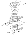
- dual flapper seal assembly 100 generally includes a body 102 having mounting surfaces 108 for interfacing with the housing 30 in a substantially fluid tight manner.
- Body 102 defines a valve mount that may be formed as separate component as depicted in FIG. 2 , or may be formed integrally with housing 30, cannula 20 or any other appropriate component of surgical portal apparatus 10.
- a primary valve includes major flapper 110, which, when in a first position, abuts a portion of body 102 to form a fluid-tight interface therewith.
- a secondary valve includes minor flapper 112, which, when in an initial position abuts a portion of major flapper 110 to form fluid-tight interface therewith.
- Major flapper 110 and minor flapper 112 are both mounted pivotally with respect to an axis "P," which is transverse to a longitudinal axis of the cannula 20. Together, major flapper 110 and minor flapper 112 serve to seal passageway 28 in the absence of an instrument. As described in greater detail below, minor flapper 112 may pivot about axis "P" to move to an actuated position to permit passage of a narrow instrument 40, while major flapper 110 and minor flapper 112 may both pivot together about axis "P" to move major flapper 110 to a second position to permit passage of a broad instrument 50.
- Body 102 includes a pair of hanging body brackets 114 each with a bore 116 along a pivot axis "P.”
- Body brackets 114 are spaced to receive major brackets 120 extending proximally from major flapper 110, such that holes 122 through major brackets 120 are aligned with bores 116 along axis "P.”
- major brackets 120 are spaced to receive minor brackets 124 extending proximally from minor flapper 112, such that holes 126 through minor brackets 124 are align with holes 122 along axis "P.”
- minor brackets 124 are spaced to receive torsion spring 130 between them, such that torsion spring 130 is aligned with axis "P.”
- Pivot pin 134 is inserted through bores 116, holes 122, 126 and torsion spring 130.
- Pivot pin 134 may be press fit within bores 116 or attached to body by other means to secure major flapper 110, minor flapper 112 and torsion spring 130. Holes 122, 126 however are sized to allow major flapper and minor flapper to pivot about axis "P.”
- Torsion spring 130 exerts pressure against surface 136 on minor flapper 112 and surface 138 on body 102 and thus acts as a biasing member to maintain major flapper 110 and minor flapper 112 in a closed condition.
- the pressure exerted by torsion spring 130 may also serve to compress elastomeric plug 140 and elastomeric liner 152 to create two separate flapper seals.
- a minor flapper seal is formed by elastomeric plug 140 when minor flapper 112 is in its initial position. Elastomeric plug 140 is captured within minor flapper 112 by the interface of annular notch 154 in the elastomeric plug 140 with annular rim 156 provided on an inner surface of minor flapper 112.
- elastomeric plug 140 moves along with minor flapper 112 and the closure bias imparted to minor flapper 112 may serve to compress elastomeric plug about minor opening 158 in major flapper 110 to create a seal about minor opening 158.
- elastomeric liner 152 may be compressed to form a major flapper seal. Elastomeric liner 152 is captured within body 102 by the interface of annular protrusion 160 provided on body 102 with annular channel 162 of elastomeric liner 142, and thus remains stationary within body 102. In its normally biased closed condition of its first postion, major flapper 110 abuts elastomeric liner 152 such that a seal is formed about a major opening 164 through body 102. Both major flapper 110 and minor flapper 112 are thus biased into sealing abutment with a corresponding surface fully closing opening 164 through body 102.
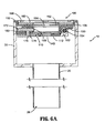
- a reduced thickness dimple 168 in elastomeric liner 152 may be aligned with lateral opening 170 through body 102. Lateral opening 170 slidingly accepts a lock member 172 such that rounded disengagement head 174 protrudes against dimple 168. Lock member 172 includes a catch 176 that interfaces with a notch 178 (best seen in FIG. 8B ) in major flapper 110. Compression spring 180 is positioned between lock member 172 and an interior wall of housing 30 such that lock member 172 is biased radially inward (see, e.g. FIG. 6A ).
- a cover plate 182 At the proximal end of dual flapper seal assembly 100, a cover plate 182 includes a central opening 184 and an annular ridge 186 protruding from a distal face 188. Annular ridge 186 is pointed in cross section such that it may dig into and deform a portion of septum seal 192 to secure its relative position against distal face 188.
- Septum seal 192 is a relatively flat member formed from a low durometer polymer making it particularly adaptable and deformable. Extending through a central portion of septum seal 192 is an orifice 194, which is capable of expanding to accommodate instruments of various sizes. Septum seal 192 is held in place between body 102 and cover plate 182 by a radial array of flaps 198 (best seen in FIG. 3 ) protruding inwardly from body 102.
- dual-flapper seal assembly 100 is depicted in place within housing 30 in a normally biased condition.
- a fluid tight connection between the mounting surfaces 108 of body 102 and housing 30 may be made by a friction fit, ultrasonic welding, adhesive or other appropriate means.
- orifice 194 in septum seal 192 remains open, passageway 28 is sealed by the fluid tight interfaces formed by elastomeric liner 152 and elastomeric plug 140 as described above.
- Narrow instrument 40 may be inserted on a distal direction from the proximal end where it first encounters septum seal 192.
- septum seal 192 deforms to expand central orifice 194. This deformation creates a fluid-tight interface about the shaft of instrument 40.
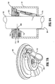
- narrow instrument 40 next encounters elastomeric plug 140 and tends to act against the bias of torsion spring 130 to open minor flapper 112, moving it to its actuated position as shown.
- minor flapper 1 12 With minor flapper 1 12 open to its actuated position, the bias provided by torsion spring 130 is not transmitted to major flapper 110. However, gravity or incidental contact between narrow instrument 40 and major flapper 110 will not tend to open major flapper 110 due to the engagement of the catch 176 of lock member 172 with the notch 178 on major flapper 110. Because major flapper 110 remains closed in its first position, it may assist in centering narrow instrument 40 within the passageway 28.
- FIG. 7B depicts dual flapper seal assembly 100 with minor flapper 112 open it its actuated position revealing the minor opening 158 through major flapper 110.
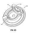
- Broad instrument 50 first encounters septum seal 192 and forms a fluid-tight interface therewith in much the same manner as narrow instrument 40 as described above. As broad instrument 50 travels distally past septum seal 192, however, broad instrument 50 next encounters dimple 168 in elastomeric liner 152. The dimple 168 is pressed against the curved shape of rounded disengagement head 174. As broad instrument 50 moves distally, lock member 172 is urged against the bias of compression spring 180, thereby disengaging catch 176 from notch 178.
- FIG. 8B depicts dual flapper seal assembly 100 with an open major flapper 110 revealing the major opening 164 through body 102.
- Narrow instrument 40 may have a shaft diameter of about 5 mm to about 18 mm, for example.
- Broad instrument 50 may have a shaft diameter from about 10 mm to about 18 mm.
- a narrow instrument is any instrument having a diameter smaller than the minor opening 158 that may be accommodated by the opening of the secondary valve, and a broad instrument is any instrument having a diameter larger than the minor opening 158.
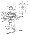
- a second embodiment of the disclosure includes an embedded valve system with a bifurcated major flapper.
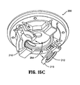
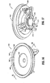
- Bifurcated flapper seal system 200 generally includes a body 202 having mounting surfaces 208 to permit a fluid tight interface with a housing, such as housing 30 described above.
- Body 202 also defines a valve mount, which may also be formed integrally with a housing, portal member or other component as described above. Mounting bifurcated flapper seal system 200 to a housing 30 permits bifurcated flapper seal system 200 to seal a passageway 28 through a cannula 20 as described above.
- a primary valve here includes two major flapper half segments 210 that each abuts a surface such that together they may form a fluid-tight interface with body 102 when primary valve is in its first position.
- Major flapper half segments 210 may be identical parts oriented oppositely.
- a secondary valve includes minor flapper 212, which abuts a portion of each of the major flapper half segments 210 to form fluid-tight interface therewith when secondary valve is in its initial position.
- Minor flapper 212 and one of the major flapper half segments 210 are pivotally mounted on an axis "P1," which is transverse to the longitudinal axis of the cannula 20.
- the other major flapper half segment 210 is pivotally mounted on an axis "P2" also transverse to the longitudinal axis of cannula 20.
- the primary valve including the pair of major flapper half segments 210, and the secondary valve, including minor flapper 212, serve to seal passageway 28 in the absence of an instrument.
- Components of the primary valve may open to a second position to permit passage of broad instrument and secondary valve may open to an actuated position to permit passage of a narrow instrument as described in greater detail below.
- bifurcated flapper seal system 200 includes a body 202 having two pairs of hanging body brackets 214. Each pair of body brackets includes a pair of bores 216 that define one of the pivot axes "P1" and "P2.” Body brackets 214 are spaced to receive major brackets 220 extending proximally from major bracket half segments 210. Likewise, major brackets 220 are spaced to receive minor brackets 224 extending proximally from minor flapper 212. Minor brackets 224 are spaced to receive torsion spring 230.
- a pivot pin 234 may be press fit into bores 216 to secure a major flapper half segment 210, minor flapper 212, and torsion spring 230 to body 202 along axis "P1" while permitting major flapper half segment 210, minor flapper 212, and torsion spring 230 to pivot about axis "P1.”
- An additional pivot pin 234 may be press fit into bores 216 to secure the other major flapper half segment 210 to body 202 while permitting the major flapper half segment 210 to pivot about axis "P2.”
- Torsion spring 230 exerts pressure against surface 236 on minor flapper 212 and surface 238 on major flapper half segment 210. This arrangement is differentiated from the arrangement of torsion spring 130 ( FIG. 5 ) of seal assembly 100 which exerts pressure on body 102. In this embodiment, because torsion spring 230 is positioned to exert pressure on one of the major flapper half sections 210, the bias is not transmitted through this section 210.
- torsion spring 230 serves as a biasing member to bias minor flapper 212 to a closed condition with respect to the major flapper half segment 210 mounted pivotally about axis "P1."
- torsion spring 230 may compress elastomeric plug 240 against both major flapper half sections 210 to form a minor flapper seal.
- An independent biasing member may be provided for each major flapper half section 210 by spring ring 242.
- Spring ring 242 includes an array of holes 244 that correspond to an array of alignment protrusions 246 on body 202 to facilitate attachment of the spring ring 242 to body 202.
- Spring ring 242 includes two pairs of biasing fingers 248 arranged oppositely such that each pair of biasing fingers 248 may contact a surface 250 on major flapper half segments 210. Biasing fingers 248 tend to bias the major flapper half segments 210 to a closed condition where they may compress a portion of elastomeric liner 252 to create a major flapper seal.
- Elastomeric liner 252 is captured within body 202 and remains stationary within body 202.
- Elastomeric liner 252 includes a pair of oppositely positioned, reduced thickness dimples 268, each aligned with a lateral opening 270 through body 202.
- Each lateral opening 270 slidingly accepts a lock member 272 such that a rounded disengagement head 274 may protrude against the corresponding dimple 268.
- Each lock member 272 includes a catch 276 that interfaces with a notch 278 formed in major flapper half segments 210.
- Biasing tabs 280 are positioned on spring ring 242 such that both lock members 272 are biased radially inward (see, e.g. FIG. 6A ).
- a cover plate 282 secures septum seal 292 to body 202.
- Cover plate 282 and septum seal 292 having orifice 294 may function identically as cover plate 182 and septum seal 192 described above with reference to FIG. 5 .
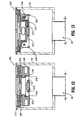
- bifurcated flapper seal assembly 200 is depicted in place within housing 30 in a normally biased condition.
- lock members 272 are biased inwardly by biasing tabs 280.
- the catch 276 of each lock member 272 is engaged with the notch 278 formed in the major flapper half segments 210, thus preventing major flapper half segments from moving to an open second position.
- major flapper half segments 210 are biased to a closed first position by biasing fingers 248 and minor flapper 212 is biased to a closed initial position by torsion spring 230.
- passageway 28 is sealed by fluid tight interfaces formed by the closure biases imparted on major flapper half segments 21 and on minor flapper 212.
- the use of bifurcated flapper seal assembly 200 with narrow instrument 40 is substantially similar to the use of dual flapper seal assembly 100 with narrow instrument 40 described with reference to FIG. 7A .
- Narrow instrument 40 first encounters septum seal 292 as it enters seal assembly 200 from a proximal side moving in a distal direction.
- septum seal 292 deforms to expand central orifice 294. This deformation creates a fluid-tight interface about the shaft of instrument 40.
- narrow instrument 40 next encounters elastomeric plug 240 and tends to act against the bias of torsion spring 230 to open minor flapper 212 to its actuated position as shown.
- major flapper half segments 210 may assist in centering narrow instrument 40 within the passageway 28.
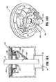
- FIG. 14B depicts bifurcated flapper seal assembly 200 with minor flapper 212 open to its actuated position revealing minor opening 258.
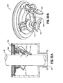
- FIG. 15C depicts bifurcated flapper seal assembly 200 with open major flapper half segments 210 revealing major opening 264.
- Trifurcated flapper seal system 300 generally includes a body 302 having mounting surfaces 308 to permit a fluid tight interface with a housing, such as housing 30 described above. Again, body 302 also defines a valve mount, which may also be formed integrally with a housing, portal member or other component as described above. Mounting trifurcated flapper seal system 300 to a housing 30 permits trifurcated flapper seal system 300 to seal a passageway 28 through a cannula 20 as described above.
- a primary valve here has a first position wherein three major flapper third segments 310 that each abuts a surface such that together they may form a fluid-tight interface with body 302.
- Major flapper third segments 310 may be identical parts oriented cooperatively around body 302.
- a secondary valve includes minor flapper 312, which abuts a portion of the major flapper third segments 310 to form fluid-tight interface therewith.
- Minor flapper 312 and one of the major flapper third segments 310 are pivotally mounted on an axis "P3" transverse to the longitudinal axis of the cannula 20.
- the other major flapper third segments 310 are pivotally mounted on an axes "P4" and "P5,” each also transverse to the longitudinal axis of cannula 20.
- the primary valve including the set of major flapper third segments 310, in a first position and the secondary valve, including minor flapper 312, in an initial position serve to seal passageway 28 in the absence of an instrument.
- the primary valve may open to a second position to permit passage of a broad instrument and the secondary valve may open to an actuated position to permit passage of a narrow instrument as described in greater detail below.
- trifurcated flapper seal assembly 300 includes a body 302 having three pairs of hanging body brackets 314.
- Each pair of body brackets 314 includes a pair of bores 316 that define one of the pivot axes "P3," "P4" and "P5.”
- Body brackets 314 include tapered guide surfaces and are spaced to receive major brackets 320 extending proximally from major bracket third segments 310.
- major brackets 320 are spaced to receive minor bracket 324 extending proximally from minor flapper 312.
- Minor bracket 324 does not accommodate a torsion spring like the minor brackets 124 and 224 discussed with reference to FIGS. 5 and 11 above. In this embodiment, the torsion spring is replaced with leaf spring 330.
- Pivot bosses 334 extend laterally from both sides of major brackets 320. Exterior pivot bosses 334 may be snap fit into bores 316 to pivotally secure a major flapper third segments 310 to body 302. As best seen in FIGS. 19 and 20 , minor flapper 312 may be snap fit onto the interior pivot bosses 334 of one of the major flapper third segments 310 to pivotally secure minor flapper 312 thereto. The major flapper third segment 310 attached to minor flapper 312 may be snap fit to body 302 in the same manner as major flapper third segments 310 not attached to minor flapper 312.
- Leaf spring 330 exerts pressure against surface 336 on minor flapper 312.
- Leaf spring 330 biases minor flapper 312 to a closed condition and may compress elastomeric o-ring 340 against all three major flapper third segments 310 to form a minor flapper seal.
- Leaf spring 330 thus imparts a bias on each of the major flapper third segments 310 when minor flapper 312 is in a closed condition.
- An additional bias may be imposed on third segments 310, even when minor flapper 312 is in an open condition, by spring ring 342.
- Spring ring 342 includes an open central portion 344 that fits around an array of protrusions 346 on body 302 to facilitate attachment of the spring ring 342 to body 302.
- Spring ring 342 may be affixed to body 302 by a friction fit or with an appropriate adhesive.
- Spring ring 342 includes three pairs of biasing fingers 348 arranged such that each pair of biasing fingers 348 may contact a surface 350 on major flapper third segments 310. Biasing fingers 348 tend to bias the major flapper third segments 310 to a closed condition where they may contact a portion of body 302 to create a major flapper seal.
- a cover plate 382 At the proximal end of trifurcated flapper seal system 300, a cover plate 382 includes a central opening 384 and an annular ridge 386 protruding from a distal face 388. Annular ridge 386 is tapered or pointed in cross section such that it may dig into and deform a portion of septum seal 392 to secure its relative position against distal face 388. Septum seal 392 is a relatively flat member formed from a low durometer polymer making it particularly adaptable and deformable.
- septum seal 392 Extending through a central portion of septum seal 392 is an orifice 394, which is capable of expanding to accommodate instruments of various sizes. Septum seal 392 is held in place between body 302 and cover plate 382 by a radial array of flaps 398 (best seen in FIG. 16 ) protruding inwardly from body 302.
- trifurcated flapper seal assembly 300 is depicted in place within housing 30 in a normally biased condition.
- Major flapper third segments 310 are biased to a closed position by biasing fingers 348 such that the primary valve is in its first position.
- An additional bias is provided through minor flapper 312, which is itself biased to a closed initial position by leaf spring 330.
- passageway 28 is sealed by fluid tight interfaces formed by the bias imparted on the set of major flapper third segments 310, and minor flapper 312.
- Narrow instrument 40 first encounters septum seal 392 as it enters seal assembly 300 from a proximal side moving in a distal direction.
- septum seal 392 deforms to expand central orifice 394. This deformation creates a fluid-tight interface about the shaft of instrument 40.
- narrow instrument 40 next encounters minor flapper 312 and it tends to act against the bias of leaf spring 330 to open minor flapper 312, moving the secondary valve to its actuated position as shown.
- FIG. 22B depicts trifurcated flapper seal assembly 300 with a minor flapper 312 open to its actuated position revealing opening 358 formed by the combination of major flapper third segments 310.
- FIG. 23B depicts trifurcated flapper seal assembly 300 with open major flapper third segments 310 revealing an opening 364 through body 302.
Landscapes
- Health & Medical Sciences (AREA)
- Surgery (AREA)
- Life Sciences & Earth Sciences (AREA)
- Biomedical Technology (AREA)
- Nuclear Medicine, Radiotherapy & Molecular Imaging (AREA)
- Engineering & Computer Science (AREA)
- Pathology (AREA)
- Heart & Thoracic Surgery (AREA)
- Medical Informatics (AREA)
- Molecular Biology (AREA)
- Animal Behavior & Ethology (AREA)
- General Health & Medical Sciences (AREA)
- Public Health (AREA)
- Veterinary Medicine (AREA)
- Surgical Instruments (AREA)
Claims (12)
- Chirurgische Zugangsvorrichtung (10), die einen Zugriff auf eine Gewebestelle ermöglicht, welche umfasst:ein Zugangsteil (20), welches zur Positionierung innerhalb von Körpergewebe dimensioniert ist und welches eine Längsachse (A) definiert, wobei das Zugangsteil (20) eine Längsdurchführung (28) hat, wodurch es Zugriff auf eine Gewebestelle ermöglicht, wobei das Zugangsteil (20) eine Ventilbefestigung hat, welche eine in Verbindung mit der Längsdurchführung (28) stehende große Öffnung (164, 264, 364) definiert;ein primäres Ventil, welches an dem Zugangsteil (20) befestigt ist, wobei das primäre Ventil ausgebildet ist, sich zwischen einer ersten Position, in der es die große Öffnung (164, 264, 364) der Ventilbefestigung im Wesentlichen abdichtet, und einer zweiten Position, welche gegenüber der großen Öffnung (164, 264, 364) versetzt ist, und den Durchlass eines relativ breiten chirurgischen Instruments (50) durch die große Öffnung (164, 264, 364) ermöglicht, zu bewegen, wobei das primäre Ventil eine kleine Öffnung (158, 258, 358) definiert, welche derart dimensioniert ist, dass sie ein relativ schmales Instrument (40) aufnimmt; undein sekundäres Ventil, welches an dem Zugangsteil (20) befestigt ist, wobei das sekundäre Ventil ausgebildet ist, sich relativ zu dem primären Ventil zwischen einer Ausgangsposition, welche im Wesentlichen die kleine Öffnung des primären Ventils abdichtet, und einer Betätigungsposition, welche gegenüber der kleinen Öffnung (158, 258, 358) versetzt ist, und den Durchlass des schmalen Instruments (40) ermöglicht, zu bewegen;dadurch gekennzeichnet, dass die Zugangsvorrichtung (10) weiterhin umfasst: (i) ein Verriegelungsteil (172, 272), welches ausgebildet ist, das primäre Ventil bei Einführen des schmalen Instruments daran zu hindern, sich zu der zweiten Position hin zu bewegen; und (ii) eine Freigabe-Oberfläche (174, 274), welche das breite Instrument (50) derart erfasst, dass das Verriegelungsteil (172, 272) versetzt wird, damit das primäre Ventil sich öffnen kann, um Durchlass des breiten Instruments (50) zu ermöglichen.
- Die chirurgische Zugangsvorrichtung (10) nach Anspruch 1, wobei zumindest eines des primären Ventils und des sekundären Ventils für eine Schwenkbewegung um eine Achse (P) quer zu der longitudinalen Achse (A) ausgebildet ist.
- Die chirurgische Zugangsvorrichtung (1) nach Anspruch 1, weiterhin umfassend ein Gehäuse (30), welches mit einem proximales Ende des Zugangsteils (20) verbunden ist, wobei die Ventilbefestigung mit dem Gehäuse (30) verbunden ist.
- Die chirurgische Zugangsvorrichtung (10) nach Anspruch 2, wobei das primäre Ventil derart radial segmentiert ist, dass eine Vielzahl von Segmenten (210, 310) um die große Öffnung (264, 364) herum angeordnet ist, wobei jedes Segment (210, 310) ausgebildet ist, um eine unabhängige Achse (P1, P2, P3, P4, P5) quer zu einer Längsachse (A) des Durchgangs (28) zu schwenken.
- Die chirurgische Zugangsvorrichtung (10) nach Anspruch 4, wobei das primäre Ventil zweiteilig gegliedert ist und zwei radiale Segmente (210) beinhaltet.
- Die chirurgische Zugangsvorrichtung (10) nach Anspruch 4, wobei das primäre Ventil dreiteilig gegliedert ist und drei radiale Segmente (310) beinhaltet.
- Die chirurgische Zugangsvorrichtung (10) nach Anspruch 1, weiterhin umfassend eine Scheidewanddichtung (192, 292, 392), welche in Bezug auf das primäre Ventil proximal angeordnet ist, wobei die Scheidewanddichtung (192, 292, 392) ausgebildet ist, ein Instrument (40, 50) zu erfassen und mit diesem eine Dichtung auszubilden.
- Die chirurgische Zugangsvorrichtung (10) nach Anspruch 1, wobei das primäre Ventil und das sekundäre Ventil in Bezug auf ihre erste bzw. Ausgangsposition derart normal vorgespannt sind, dass eine flüssigkeitsdichte Dichtung in der Abwesenheit eines Instruments (40, 50) quer über den Durchgang (28) aufrechterhalten wird.
- Kanülendichtung (200, 300) umfassend:eine Ventilbefestigung, die die Kanülendichtung quer über einen Durchgang (28) durch eine Kanüle (20), welche eine Längsachse (A) definiert, befestigt;ein primäres Ventil, das eine große Öffnung (264, 364) durch die Ventilbefestigung selektiv abdichtet, wobei das primäre Ventil radial segmentiert ist, und eine Vielzahl von Segmenten (210, 310) beinhaltet, wobei jedes Segment (210, 310) um eine Achse (P1, P2, P3, P4, P5) quer zu der longitudinalen Achse (A) der Kanüle (20) schwenkbar befestigt ist und beweglich ist, um das primäre Ventil zwischen einer ersten Position und einer zweiten Position zu bewegen, wobei die Vielzahl von Segmenten (210, 310) derart angeordnet ist, dass sie eine kleine Öffnung (258, 358) durch das primäre Ventil definiert, wenn es in der ersten Position ist; undein sekundäres Ventil, das die kleine Öffnung (258, 358) selektiv abdichtet, wobei das sekundäre Ventil mit mindestens einem der Segmente (210, 310) derart verbunden ist, dass das sekundäre Ventil versetzt wird, wenn das primäre Ventil zwischen der ersten Position und der zweiten Position bewegt wird;dadurch gekennzeichnet, dass die Kanülendichtung (200, 300) weiterhin umfasst: (i) ein Verriegelungsteil (172, 272), welches ausgebildet ist, zu verhindern, dass die Vielzahl von Segmenten (210, 310) bei Einführen eines schmalen Instruments (40) schwenkt; und (ii) eine Freigabe-Oberfläche (174, 274) zum Erfassen eines breiten Instruments (50), derart dass das Verriegelungsteil (172, 272) versetzt wird, damit das primäre Ventil schwenken kann, um den Durchlass des breiten Instruments (50) zu ermöglichen.
- Die Kanülendichtung (200, 300) nach Anspruch 9, wobei das sekundäre Ventil um die Achse (P1, P3), um welche zumindest eines der Segmente (210, 310) schwenkbar befestigt ist, schwenkbar befestigt ist.
- Die Kanülendichtung (200, 300) nach Anspruch 10, wobei das sekundäre Ventil mittels eines Vorspannteils (230, 330) in eine Ausgangsposition vorgespannt ist, um die kleine Öffnung (258, 358) abzudichten.
- Die Kanülendichtung (200, 300) nach Anspruch 9, weiterhin umfassend eine Scheidewanddichtung (192, 292, 392), welche in Bezug auf das primäre Ventil proximal angeordnet ist, wobei die Scheidewanddichtung (192, 292, 392) ausgebildet ist, ein Instrument (40, 50) zu erfassen und mit diesem eine Dichtung auszubilden.
Applications Claiming Priority (2)
| Application Number | Priority Date | Filing Date | Title |
|---|---|---|---|
| US4381408P | 2008-04-10 | 2008-04-10 | |
| US12/403,647 US8007473B2 (en) | 2008-04-10 | 2009-03-13 | Access assembly with multi-flapper design |
Publications (2)
| Publication Number | Publication Date |
|---|---|
| EP2108320A1 EP2108320A1 (de) | 2009-10-14 |
| EP2108320B1 true EP2108320B1 (de) | 2011-08-17 |
Family
ID=40823573
Family Applications (1)
| Application Number | Title | Priority Date | Filing Date |
|---|---|---|---|
| EP09251066A Not-in-force EP2108320B1 (de) | 2008-04-10 | 2009-04-09 | Zugangsanordnung für ein Mehrklappen-Design |
Country Status (6)
| Country | Link |
|---|---|
| US (1) | US8007473B2 (de) |
| EP (1) | EP2108320B1 (de) |
| JP (1) | JP5492442B2 (de) |
| AT (1) | ATE520363T1 (de) |
| AU (1) | AU2009201148A1 (de) |
| CA (1) | CA2661249A1 (de) |
Families Citing this family (13)
| Publication number | Priority date | Publication date | Assignee | Title |
|---|---|---|---|---|
| WO2011097639A2 (en) | 2010-02-08 | 2011-08-11 | Access Scientific, Inc. | Access device |
| WO2013026045A1 (en) | 2011-08-17 | 2013-02-21 | Access Scientific, Inc. | Access device with valve |
| US9468751B2 (en) * | 2012-12-05 | 2016-10-18 | Medtronic, Inc. | Medical device anchoring apparatus |
| US9566087B2 (en) * | 2013-03-15 | 2017-02-14 | Access Scientific, Llc | Vascular access device |
| US9414830B2 (en) | 2013-06-14 | 2016-08-16 | Covidien Lp | Surgical access assembly including adhesive members for secure attachment to skin surfaces |
| WO2016176065A1 (en) | 2015-04-30 | 2016-11-03 | Access Scientific, Llc | Vascular access device |
| USD810290S1 (en) | 2016-01-29 | 2018-02-13 | Medovex Corp. | Surgical portal driver |
| US10588710B2 (en) | 2016-11-15 | 2020-03-17 | Medtronic, Inc. | Medical device anchoring |
| JP7132221B2 (ja) * | 2016-12-02 | 2022-09-06 | アプライド マテリアルズ インコーポレイテッド | 低粒子防護型フラッパバルブ |
| WO2018191547A1 (en) | 2017-04-14 | 2018-10-18 | Access Scientific, Llc | Vascular access device |
| US10610681B2 (en) | 2017-08-29 | 2020-04-07 | Medtronic Inc. | Medical device anchoring |
| KR20200051039A (ko) * | 2017-09-29 | 2020-05-12 | 어플라이드 머티어리얼스, 인코포레이티드 | 듀얼 포트 원격 플라즈마 세정 격리 밸브 |
| US10569059B2 (en) | 2018-03-01 | 2020-02-25 | Asspv, Llc | Guidewire retention device |
Family Cites Families (17)
| Publication number | Priority date | Publication date | Assignee | Title |
|---|---|---|---|---|
| US5308336A (en) | 1982-09-28 | 1994-05-03 | Applied Medical Resources | Seal protection mechanism |
| US5104383A (en) * | 1989-10-17 | 1992-04-14 | United States Surgical Corporation | Trocar adapter seal and method of use |
| US5211633A (en) | 1992-06-24 | 1993-05-18 | Stouder Jr Albert E | Selectable seal cannula |
| US5496280A (en) * | 1992-07-02 | 1996-03-05 | Applied Medical Resources Corporation | Trocar valve assembly |
| US5342315A (en) * | 1993-04-12 | 1994-08-30 | Ethicon, Inc. | Trocar seal/protector assemblies |
| GB2284452A (en) | 1993-12-03 | 1995-06-07 | Advanced Surgical Devices Limi | Sealing |
| CA2186517A1 (en) * | 1994-03-26 | 1995-10-05 | William John Hoskin | Gas-tight seal for surgical trocars |
| US5569205A (en) | 1994-07-14 | 1996-10-29 | Hart; Charles C. | Multiport trocar |
| GB2298906A (en) | 1995-03-15 | 1996-09-18 | Microsurgical Equipment Ltd | Modular seal system for trocars |
| US5820600A (en) | 1996-05-14 | 1998-10-13 | Innerdyne, Inc. | Adjustable introducer valve |
| US5858007A (en) * | 1996-07-03 | 1999-01-12 | C. R. Bard, Inc. | Hemostatic catheter introducer |
| DE29717940U1 (de) | 1997-10-09 | 1997-11-27 | ETB Endoskopische Technik GmbH Berlin, 12555 Berlin | Trokarhülse |
| US6228061B1 (en) | 1998-02-03 | 2001-05-08 | Imagyn Medical Technologies California, Inc. | Trocar seal system having dual seals |
| JP2001137253A (ja) * | 1999-11-12 | 2001-05-22 | Olympus Optical Co Ltd | トロッカー外套管 |
| US6551270B1 (en) | 2000-08-30 | 2003-04-22 | Snowden Pencer, Inc. | Dual lumen access port |
| EP1443991A4 (de) | 2001-11-13 | 2007-03-14 | Applied Med Resources | Trokarsystem mit mehrfachverschluss |
| US7163525B2 (en) * | 2004-12-17 | 2007-01-16 | Ethicon Endo-Surgery, Inc. | Duckbill seal protector |
-
2009
- 2009-03-13 US US12/403,647 patent/US8007473B2/en not_active Expired - Fee Related
- 2009-03-23 AU AU2009201148A patent/AU2009201148A1/en not_active Abandoned
- 2009-04-01 CA CA002661249A patent/CA2661249A1/en not_active Abandoned
- 2009-04-02 JP JP2009090555A patent/JP5492442B2/ja not_active Expired - Fee Related
- 2009-04-09 AT AT09251066T patent/ATE520363T1/de not_active IP Right Cessation
- 2009-04-09 EP EP09251066A patent/EP2108320B1/de not_active Not-in-force
Also Published As
| Publication number | Publication date |
|---|---|
| JP5492442B2 (ja) | 2014-05-14 |
| US8007473B2 (en) | 2011-08-30 |
| JP2009247904A (ja) | 2009-10-29 |
| CA2661249A1 (en) | 2009-10-10 |
| EP2108320A1 (de) | 2009-10-14 |
| US20090259186A1 (en) | 2009-10-15 |
| ATE520363T1 (de) | 2011-09-15 |
| AU2009201148A1 (en) | 2010-09-30 |
Similar Documents
| Publication | Publication Date | Title |
|---|---|---|
| US8007473B2 (en) | Access assembly with multi-flapper design | |
| EP2361567B1 (de) | Zugangsvorrichtung mit integralem Schnellverschlussventil und Rückschlagventil | |
| EP2229897B1 (de) | Chirurgische Portalvorrichtung mit beweglichem Gehäuse | |
| US8968249B2 (en) | Introducer seal assembly | |
| EP1997445B1 (de) | Selbstzusammenziehende Öffnungsdichtung | |
| EP1992298B1 (de) | Flexible Kanüle und zugehörige Dichtung | |
| US8409146B2 (en) | Surgical access apparatus with centering mechanism | |
| US8002750B2 (en) | Access apparatus with shallow zero closure valve | |
| EP2233090A1 (de) | Mit Feder versehenes, artikulierendes, chirurgisches Portalgerät | |
| EP2664289B1 (de) | Chirurgische Zugangsvorrichtung mit Aufhängeranbringung, die mit Faltenbalgen zusammenarbeitet | |
| JP6066428B2 (ja) | 低輪郭の外科用万能アクセスポート | |
| EP1994898B1 (de) | Chirurgische Portalvorrichtung mit Armaturenanordnung | |
| US8932275B2 (en) | Surgical seal assembly | |
| EP2664290B1 (de) | Chirurgische Zugangsvorrichtung mit einen spherisches Gelenk mit Selbszentrier-Mechanismus | |
| EP2233089A1 (de) | Angetriebener Trokar mit variablem Dichtungsdurchmesser mit einem Längsverschiebungsmechanismus |
Legal Events
| Date | Code | Title | Description |
|---|---|---|---|
| PUAI | Public reference made under article 153(3) epc to a published international application that has entered the european phase |
Free format text: ORIGINAL CODE: 0009012 |
|
| AK | Designated contracting states |
Kind code of ref document: A1 Designated state(s): AT BE BG CH CY CZ DE DK EE ES FI FR GB GR HR HU IE IS IT LI LT LU LV MC MK MT NL NO PL PT RO SE SI SK TR |
|
| 17P | Request for examination filed |
Effective date: 20100401 |
|
| 17Q | First examination report despatched |
Effective date: 20100519 |
|
| GRAP | Despatch of communication of intention to grant a patent |
Free format text: ORIGINAL CODE: EPIDOSNIGR1 |
|
| GRAS | Grant fee paid |
Free format text: ORIGINAL CODE: EPIDOSNIGR3 |
|
| GRAA | (expected) grant |
Free format text: ORIGINAL CODE: 0009210 |
|
| AK | Designated contracting states |
Kind code of ref document: B1 Designated state(s): AT BE BG CH CY CZ DE DK EE ES FI FR GB GR HR HU IE IS IT LI LT LU LV MC MK MT NL NO PL PT RO SE SI SK TR |
|
| REG | Reference to a national code |
Ref country code: GB Ref legal event code: FG4D |
|
| REG | Reference to a national code |
Ref country code: CH Ref legal event code: EP |
|
| REG | Reference to a national code |
Ref country code: IE Ref legal event code: FG4D |
|
| REG | Reference to a national code |
Ref country code: DE Ref legal event code: R096 Ref document number: 602009002186 Country of ref document: DE Effective date: 20111020 |
|
| REG | Reference to a national code |
Ref country code: NL Ref legal event code: VDEP Effective date: 20110817 |
|
| REG | Reference to a national code |
Ref country code: ES Ref legal event code: FG2A Ref document number: 2370376 Country of ref document: ES Kind code of ref document: T3 Effective date: 20111214 |
|
| LTIE | Lt: invalidation of european patent or patent extension |
Effective date: 20110817 |
|
| PG25 | Lapsed in a contracting state [announced via postgrant information from national office to epo] |
Ref country code: LT Free format text: LAPSE BECAUSE OF FAILURE TO SUBMIT A TRANSLATION OF THE DESCRIPTION OR TO PAY THE FEE WITHIN THE PRESCRIBED TIME-LIMIT Effective date: 20110817 Ref country code: IS Free format text: LAPSE BECAUSE OF FAILURE TO SUBMIT A TRANSLATION OF THE DESCRIPTION OR TO PAY THE FEE WITHIN THE PRESCRIBED TIME-LIMIT Effective date: 20111217 Ref country code: SE Free format text: LAPSE BECAUSE OF FAILURE TO SUBMIT A TRANSLATION OF THE DESCRIPTION OR TO PAY THE FEE WITHIN THE PRESCRIBED TIME-LIMIT Effective date: 20110817 Ref country code: NO Free format text: LAPSE BECAUSE OF FAILURE TO SUBMIT A TRANSLATION OF THE DESCRIPTION OR TO PAY THE FEE WITHIN THE PRESCRIBED TIME-LIMIT Effective date: 20111117 Ref country code: NL Free format text: LAPSE BECAUSE OF FAILURE TO SUBMIT A TRANSLATION OF THE DESCRIPTION OR TO PAY THE FEE WITHIN THE PRESCRIBED TIME-LIMIT Effective date: 20110817 Ref country code: PT Free format text: LAPSE BECAUSE OF FAILURE TO SUBMIT A TRANSLATION OF THE DESCRIPTION OR TO PAY THE FEE WITHIN THE PRESCRIBED TIME-LIMIT Effective date: 20111219 Ref country code: FI Free format text: LAPSE BECAUSE OF FAILURE TO SUBMIT A TRANSLATION OF THE DESCRIPTION OR TO PAY THE FEE WITHIN THE PRESCRIBED TIME-LIMIT Effective date: 20110817 |
|
| REG | Reference to a national code |
Ref country code: AT Ref legal event code: MK05 Ref document number: 520363 Country of ref document: AT Kind code of ref document: T Effective date: 20110817 |
|
| PG25 | Lapsed in a contracting state [announced via postgrant information from national office to epo] |
Ref country code: PL Free format text: LAPSE BECAUSE OF FAILURE TO SUBMIT A TRANSLATION OF THE DESCRIPTION OR TO PAY THE FEE WITHIN THE PRESCRIBED TIME-LIMIT Effective date: 20110817 Ref country code: SI Free format text: LAPSE BECAUSE OF FAILURE TO SUBMIT A TRANSLATION OF THE DESCRIPTION OR TO PAY THE FEE WITHIN THE PRESCRIBED TIME-LIMIT Effective date: 20110817 Ref country code: GR Free format text: LAPSE BECAUSE OF FAILURE TO SUBMIT A TRANSLATION OF THE DESCRIPTION OR TO PAY THE FEE WITHIN THE PRESCRIBED TIME-LIMIT Effective date: 20111118 Ref country code: CY Free format text: LAPSE BECAUSE OF FAILURE TO SUBMIT A TRANSLATION OF THE DESCRIPTION OR TO PAY THE FEE WITHIN THE PRESCRIBED TIME-LIMIT Effective date: 20110817 Ref country code: LV Free format text: LAPSE BECAUSE OF FAILURE TO SUBMIT A TRANSLATION OF THE DESCRIPTION OR TO PAY THE FEE WITHIN THE PRESCRIBED TIME-LIMIT Effective date: 20110817 Ref country code: AT Free format text: LAPSE BECAUSE OF FAILURE TO SUBMIT A TRANSLATION OF THE DESCRIPTION OR TO PAY THE FEE WITHIN THE PRESCRIBED TIME-LIMIT Effective date: 20110817 |
|
| PG25 | Lapsed in a contracting state [announced via postgrant information from national office to epo] |
Ref country code: BE Free format text: LAPSE BECAUSE OF FAILURE TO SUBMIT A TRANSLATION OF THE DESCRIPTION OR TO PAY THE FEE WITHIN THE PRESCRIBED TIME-LIMIT Effective date: 20110817 |
|
| PG25 | Lapsed in a contracting state [announced via postgrant information from national office to epo] |
Ref country code: SK Free format text: LAPSE BECAUSE OF FAILURE TO SUBMIT A TRANSLATION OF THE DESCRIPTION OR TO PAY THE FEE WITHIN THE PRESCRIBED TIME-LIMIT Effective date: 20110817 Ref country code: CZ Free format text: LAPSE BECAUSE OF FAILURE TO SUBMIT A TRANSLATION OF THE DESCRIPTION OR TO PAY THE FEE WITHIN THE PRESCRIBED TIME-LIMIT Effective date: 20110817 |
|
| PG25 | Lapsed in a contracting state [announced via postgrant information from national office to epo] |
Ref country code: HR Free format text: LAPSE BECAUSE OF FAILURE TO SUBMIT A TRANSLATION OF THE DESCRIPTION OR TO PAY THE FEE WITHIN THE PRESCRIBED TIME-LIMIT Effective date: 20111109 Ref country code: RO Free format text: LAPSE BECAUSE OF FAILURE TO SUBMIT A TRANSLATION OF THE DESCRIPTION OR TO PAY THE FEE WITHIN THE PRESCRIBED TIME-LIMIT Effective date: 20110817 Ref country code: EE Free format text: LAPSE BECAUSE OF FAILURE TO SUBMIT A TRANSLATION OF THE DESCRIPTION OR TO PAY THE FEE WITHIN THE PRESCRIBED TIME-LIMIT Effective date: 20110817 |
|
| PLBE | No opposition filed within time limit |
Free format text: ORIGINAL CODE: 0009261 |
|
| STAA | Information on the status of an ep patent application or granted ep patent |
Free format text: STATUS: NO OPPOSITION FILED WITHIN TIME LIMIT |
|
| PG25 | Lapsed in a contracting state [announced via postgrant information from national office to epo] |
Ref country code: DK Free format text: LAPSE BECAUSE OF FAILURE TO SUBMIT A TRANSLATION OF THE DESCRIPTION OR TO PAY THE FEE WITHIN THE PRESCRIBED TIME-LIMIT Effective date: 20110817 |
|
| 26N | No opposition filed |
Effective date: 20120521 |
|
| REG | Reference to a national code |
Ref country code: DE Ref legal event code: R097 Ref document number: 602009002186 Country of ref document: DE Effective date: 20120521 |
|
| PG25 | Lapsed in a contracting state [announced via postgrant information from national office to epo] |
Ref country code: MC Free format text: LAPSE BECAUSE OF NON-PAYMENT OF DUE FEES Effective date: 20120430 |
|
| PGFP | Annual fee paid to national office [announced via postgrant information from national office to epo] |
Ref country code: ES Payment date: 20120426 Year of fee payment: 4 |
|
| PG25 | Lapsed in a contracting state [announced via postgrant information from national office to epo] |
Ref country code: MK Free format text: LAPSE BECAUSE OF FAILURE TO SUBMIT A TRANSLATION OF THE DESCRIPTION OR TO PAY THE FEE WITHIN THE PRESCRIBED TIME-LIMIT Effective date: 20110817 |
|
| PG25 | Lapsed in a contracting state [announced via postgrant information from national office to epo] |
Ref country code: BG Free format text: LAPSE BECAUSE OF FAILURE TO SUBMIT A TRANSLATION OF THE DESCRIPTION OR TO PAY THE FEE WITHIN THE PRESCRIBED TIME-LIMIT Effective date: 20111117 |
|
| PG25 | Lapsed in a contracting state [announced via postgrant information from national office to epo] |
Ref country code: MT Free format text: LAPSE BECAUSE OF FAILURE TO SUBMIT A TRANSLATION OF THE DESCRIPTION OR TO PAY THE FEE WITHIN THE PRESCRIBED TIME-LIMIT Effective date: 20110817 |
|
| PGFP | Annual fee paid to national office [announced via postgrant information from national office to epo] |
Ref country code: IT Payment date: 20130422 Year of fee payment: 5 |
|
| PG25 | Lapsed in a contracting state [announced via postgrant information from national office to epo] |
Ref country code: HR Free format text: LAPSE BECAUSE OF FAILURE TO SUBMIT A TRANSLATION OF THE DESCRIPTION OR TO PAY THE FEE WITHIN THE PRESCRIBED TIME-LIMIT Effective date: 20110817 |
|
| REG | Reference to a national code |
Ref country code: CH Ref legal event code: PL |
|
| PG25 | Lapsed in a contracting state [announced via postgrant information from national office to epo] |
Ref country code: CH Free format text: LAPSE BECAUSE OF NON-PAYMENT OF DUE FEES Effective date: 20130430 Ref country code: LI Free format text: LAPSE BECAUSE OF NON-PAYMENT OF DUE FEES Effective date: 20130430 |
|
| PG25 | Lapsed in a contracting state [announced via postgrant information from national office to epo] |
Ref country code: TR Free format text: LAPSE BECAUSE OF FAILURE TO SUBMIT A TRANSLATION OF THE DESCRIPTION OR TO PAY THE FEE WITHIN THE PRESCRIBED TIME-LIMIT Effective date: 20110817 |
|
| PG25 | Lapsed in a contracting state [announced via postgrant information from national office to epo] |
Ref country code: LU Free format text: LAPSE BECAUSE OF NON-PAYMENT OF DUE FEES Effective date: 20120409 |
|
| PG25 | Lapsed in a contracting state [announced via postgrant information from national office to epo] |
Ref country code: HU Free format text: LAPSE BECAUSE OF FAILURE TO SUBMIT A TRANSLATION OF THE DESCRIPTION OR TO PAY THE FEE WITHIN THE PRESCRIBED TIME-LIMIT Effective date: 20090409 |
|
| PG25 | Lapsed in a contracting state [announced via postgrant information from national office to epo] |
Ref country code: IT Free format text: LAPSE BECAUSE OF NON-PAYMENT OF DUE FEES Effective date: 20140409 |
|
| REG | Reference to a national code |
Ref country code: ES Ref legal event code: FD2A Effective date: 20151229 |
|
| PG25 | Lapsed in a contracting state [announced via postgrant information from national office to epo] |
Ref country code: ES Free format text: LAPSE BECAUSE OF NON-PAYMENT OF DUE FEES Effective date: 20140410 |
|
| REG | Reference to a national code |
Ref country code: FR Ref legal event code: PLFP Year of fee payment: 8 |
|
| REG | Reference to a national code |
Ref country code: FR Ref legal event code: PLFP Year of fee payment: 9 |
|
| PGFP | Annual fee paid to national office [announced via postgrant information from national office to epo] |
Ref country code: FR Payment date: 20170322 Year of fee payment: 9 |
|
| PGFP | Annual fee paid to national office [announced via postgrant information from national office to epo] |
Ref country code: IE Payment date: 20170323 Year of fee payment: 9 Ref country code: GB Payment date: 20170324 Year of fee payment: 9 |
|
| PGFP | Annual fee paid to national office [announced via postgrant information from national office to epo] |
Ref country code: DE Payment date: 20170321 Year of fee payment: 9 |
|
| REG | Reference to a national code |
Ref country code: DE Ref legal event code: R119 Ref document number: 602009002186 Country of ref document: DE |
|
| GBPC | Gb: european patent ceased through non-payment of renewal fee |
Effective date: 20180409 |
|
| REG | Reference to a national code |
Ref country code: IE Ref legal event code: MM4A |
|
| PG25 | Lapsed in a contracting state [announced via postgrant information from national office to epo] |
Ref country code: DE Free format text: LAPSE BECAUSE OF NON-PAYMENT OF DUE FEES Effective date: 20181101 |
|
| PG25 | Lapsed in a contracting state [announced via postgrant information from national office to epo] |
Ref country code: GB Free format text: LAPSE BECAUSE OF NON-PAYMENT OF DUE FEES Effective date: 20180409 |
|
| PG25 | Lapsed in a contracting state [announced via postgrant information from national office to epo] |
Ref country code: IE Free format text: LAPSE BECAUSE OF NON-PAYMENT OF DUE FEES Effective date: 20180409 Ref country code: FR Free format text: LAPSE BECAUSE OF NON-PAYMENT OF DUE FEES Effective date: 20180430 |