EP2108459A1 - Düse zum Zerstäuben einer Flüssigkeit - Google Patents
Düse zum Zerstäuben einer Flüssigkeit Download PDFInfo
- Publication number
- EP2108459A1 EP2108459A1 EP09157562A EP09157562A EP2108459A1 EP 2108459 A1 EP2108459 A1 EP 2108459A1 EP 09157562 A EP09157562 A EP 09157562A EP 09157562 A EP09157562 A EP 09157562A EP 2108459 A1 EP2108459 A1 EP 2108459A1
- Authority
- EP
- European Patent Office
- Prior art keywords
- nozzle
- rotation
- channel
- chamber
- guide element
- Prior art date
- Legal status (The legal status is an assumption and is not a legal conclusion. Google has not performed a legal analysis and makes no representation as to the accuracy of the status listed.)
- Granted
Links
Images


Classifications
-
- B—PERFORMING OPERATIONS; TRANSPORTING
- B05—SPRAYING OR ATOMISING IN GENERAL; APPLYING FLUENT MATERIALS TO SURFACES, IN GENERAL
- B05B—SPRAYING APPARATUS; ATOMISING APPARATUS; NOZZLES
- B05B1/00—Nozzles, spray heads or other outlets, with or without auxiliary devices such as valves, heating means
- B05B1/34—Nozzles, spray heads or other outlets, with or without auxiliary devices such as valves, heating means designed to influence the nature of flow of the liquid or other fluent material, e.g. to produce swirl
- B05B1/3405—Nozzles, spray heads or other outlets, with or without auxiliary devices such as valves, heating means designed to influence the nature of flow of the liquid or other fluent material, e.g. to produce swirl to produce swirl
- B05B1/341—Nozzles, spray heads or other outlets, with or without auxiliary devices such as valves, heating means designed to influence the nature of flow of the liquid or other fluent material, e.g. to produce swirl to produce swirl before discharging the liquid or other fluent material, e.g. in a swirl chamber upstream the spray outlet
- B05B1/3421—Nozzles, spray heads or other outlets, with or without auxiliary devices such as valves, heating means designed to influence the nature of flow of the liquid or other fluent material, e.g. to produce swirl to produce swirl before discharging the liquid or other fluent material, e.g. in a swirl chamber upstream the spray outlet with channels emerging substantially tangentially in the swirl chamber
- B05B1/3431—Nozzles, spray heads or other outlets, with or without auxiliary devices such as valves, heating means designed to influence the nature of flow of the liquid or other fluent material, e.g. to produce swirl to produce swirl before discharging the liquid or other fluent material, e.g. in a swirl chamber upstream the spray outlet with channels emerging substantially tangentially in the swirl chamber the channels being formed at the interface of cooperating elements, e.g. by means of grooves
- B05B1/3436—Nozzles, spray heads or other outlets, with or without auxiliary devices such as valves, heating means designed to influence the nature of flow of the liquid or other fluent material, e.g. to produce swirl to produce swirl before discharging the liquid or other fluent material, e.g. in a swirl chamber upstream the spray outlet with channels emerging substantially tangentially in the swirl chamber the channels being formed at the interface of cooperating elements, e.g. by means of grooves the interface being a plane perpendicular to the outlet axis
Definitions
- the invention relates to a nozzle for atomizing a liquid having a nozzle opening, with a rotation chamber located upstream of the nozzle opening, and having at least one rotational channel opening tangentially into the rotation chamber for displacing the liquid into a rotational movement coaxial with the nozzle opening.
- Such a nozzle is from the DE 101 38 622 C2 known.
- water is atomized to improve the climate during animal husbandry.
- the generated mist droplets evaporate, whereby a cooling of the room air takes place.
- a higher humidity is achieved by enriching the room air with water.
- the atomizer is supplied with the usual and relatively low water line pressure.
- the water is introduced by means of rotation channels from the outside tangentially into a rotation chamber. The water is first from the outside to a circulating track and further transported inwards and toward the nozzle opening.
- the problem underlying the invention is to develop a nozzle of the aforementioned type such that a smaller droplet size can be achieved.
- a nozzle of the aforementioned type is specified, wherein the liquid with one of the nozzle exit direction opposing component in the rotation chamber can be introduced.
- the liquid flowing into the rotation chamber can be conducted to a rotation base of the rotation chamber.
- the opening into the rotation chamber rotation channel is directed on the one hand with a component opposite to the nozzle exit direction and on the other hand on a rotation basis. Due to the rotational channel which opens tangentially into the rotation chamber, a rotating fluid or water disk is thus initially formed on the rotation base.
- the liquid is guided in alignment with the rotation base by means of the rotation channel.
- the rotation base is arranged opposite the nozzle opening.
- a rotating fluid or water column builds up. Within the water column lower friction resistances act on the molecules than in the contact area between the water column and the wall of the rotation chamber. As a result, a greater rotational speed can be set within the water column than at the edge of the water column.
- the rotation base is formed as a conical or hemispherical recess or as a flat plane.
- this promotes the formation of the rotating water disk or water column and, on the other hand, due to the larger volume of water, the formation of a higher rotational speed of the water molecules within the water column is promoted.
- a guide piece arranged upstream of the nozzle opening has the rotation channel.
- the use of a separate guide piece allows a modular design of the nozzle. This facilitates the manufacture and replacement of individual elements in the event of a defect.
- the guide piece is composed of a first guide element and a second guide element.
- the first guide element may have the nozzle opening, the rotation channel and a first subregion of the rotation chamber.
- the nozzle opening as a fine through-hole, the rotary channel as a recessed groove, and the first portion of the rotary chamber as a recess are relatively easy to manufacture.
- the second guide element may have the rotation base as the second portion of the rotation chamber.
- the rotation base may be formed as a flat plane or a conical or hemispherical depression, which is also easy and thus inexpensive to produce without much effort.
- the height of the rotation chamber increases towards the axis of rotation of the rotational movement.
- this can take place in that the first subregion of the rotation chamber in the first guide element is designed as a conical or hemispherical depression.
- the rotation base may be formed as a conical or hemispherical recess.
- a conical or frusto-conical depression or a plateau coaxial with the nozzle opening educated on the side facing away from the rotation chamber side of the first guide element.
- a conical or frusto-conical depression or a plateau coaxial with the nozzle opening educated.
- a cylindrical part of the nozzle channel is kept comparatively short as part of the nozzle opening by this depression, whereby unnecessary friction is avoided.
- droplet formation on the end face of the guide element surrounding the nozzle opening can be effectively suppressed by the spray mist
- the rotation channels are arranged to each other such that the liquid is introduced as uniformly as possible from all sides of the rotary chamber in this.
- the effective cross section of the rotational channel or the sum of the effective cross sections of the rotational channels is preferably equal to or greater than the effective cross section of the nozzle opening.
- a cross-section of the rotation channel decreases from outside to inside in the direction of the rotation chamber, in particular with respect to the height and / or the width of the rotation channel.
- the flow velocity of the liquid is increased. This in turn leads to a higher rotational speed of the resulting water column, which ultimately favors the formation of a very fine spray.
- the nozzle opening is designed as a nozzle channel with a substantially constant effective cross-section.
- a rotating water cylinder which essentially represents the axis of rotation of the entire rotating water column, is guided from the center of the rotation chamber substantially laminarly up to the exit from the nozzle opening.
- the length of the nozzle channel corresponds to the diameter of the nozzle opening or the length of the nozzle channel is smaller than the diameter of the nozzle opening.
- at least a part of the liquid from a first of the rotation chamber facing the region of the nozzle channel or the nozzle opening to a diametrically remote from the rotation chamber and the first region second region of the nozzle channel and the nozzle opening.
- the guide piece on the rotation channel or the rotation channels in each case over the full axial length of the Leit Publisheds associated feed channels.
- Through the feed channels results in an easy to produce water supply for the rotation channels.
- a first compensation chamber formed in the guide piece between the rotation channel and the associated feed channel is provided. This makes it easy to compensate for pressure fluctuations and speed losses due to turbulent flow.
- a pressure piece for fixing the guide piece is provided. It is advantageous that can be fixed by means of this pressure piece, the guide piece in a predetermined position to the nozzle opening.
- a sintered filter can take over the function of the pressure piece.
- the pressure piece has a plurality of the feed channels respectively associated holes and between the holes and the feed channels a second compensation chamber is arranged. The supply of the fluid takes place in this case substantially annular. Thus, a sufficient supply of water is ensured without much effort even when fixing the Leit Publishedes with the pressure piece.
- a housing for receiving the nozzle is provided with an internal thread, wherein the internal thread is in engagement with an external thread of the pressure piece.
- the nozzle can be mounted by simply inserting the Leit Publishedes in the housing and then screwing the pressure piece.
- the housing and the guide piece, in particular the first guide element made in one piece.
- this combined component can be produced in a simple and inexpensive way.
- a cost-effective nozzle can be produced, which can be used for example for fire protection.
- the guide piece and / or the first guide element made of ceramic can be produced.
- an increased abrasion resistance can be realized.
- a permanent operation is guaranteed even with a permanent and / or regular use of the nozzle, such as for air conditioning and / or filtering out dust and dirt particles.
- nozzle according to the invention for air conditioning, for filtering dust and / or dirt particles and / or for fire protection.
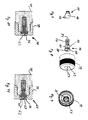
- Fig. 1 shows a perspective top view of a guide element 10.
- the guide element 10 is formed substantially cylindrical.
- a cylinder 20 is centered on a cylindrical disc 19 with respect to the disc 19th arranged smaller diameter.
- the guide element 10 can be produced in one piece by means of a lathe.
- the guide element 10 has a nozzle opening 11 in the center.
- the nozzle opening 11 is formed as a nozzle channel 12 with a constant effective cross section.
- the cylinder 20 has rotation channels 13, 14, which are formed as grooves or notches.
- the rotation channels 13, 14 lead tangentially from outside into a first subregion of a rotation chamber 15, wherein the first subregion of the rotation chamber 15 is formed as a substantially conical depression around the nozzle opening 11.
- the rotation channels 13, 14 are designed such that the recess decreases from the outside inwards, that is to say in the direction of the first subregion of the rotation chamber 15.
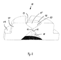
- Fig. 2 shows a perspective and sectional side view of the guide element 10 according to Fig. 1 ,
- the conical depression which represents the first portion of the rotary chamber 15, consists of a first chamber wall 16 and a chamber cone 17.
- the chamber wall 16 is frusto-conical and has a smaller angle of inclination than the chamber cone 17.
- the height of the chamber wall 16 corresponds to the depression of the rotation channels 13, 14 during the transition into the first subregion of the rotation chamber 15.
- a substantially conical depression 18 is formed coaxially with the nozzle opening 11.
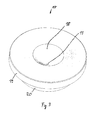
- Fig. 3 shows a plan view of the underside of the guide element 10 according to Fig. 1 ,
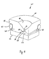
- Fig. 4 shows a perspective and sectional side view of a guide piece 21 with a guide element 10 according to Fig. 1 ,
- the guide piece 21 consists of a first guide element 10 and a second guide element 22.
- the second guide element 22 is designed as a disk and has the same diameter as the disk 19 of the first guide element 10.
- the second guide element 22 is assigned to the first guide element such that a uniformly deep, circumferential and U-shaped groove results between the second guide element 22 and the disk 19 of the first guide element 10.
- a seal 23 is arranged, which is designed here as an O-ring.
- the second guide element 22 forms a plane rotation base 24.
- a rotation chamber 25 formed by the rotation base 24 and the first portion of the rotation chamber 15 is a rotation chamber 25.
- the rotational channel 13 is arranged obliquely in the first guide element 10 such that the fluid flowing through it is introduced into the rotation chamber 25 from outside to inside and with a component directed counter to the nozzle outlet opening.
- Fig. 5 shows a sectional side view of a nozzle 26 according to the invention, which produces a fine spray 27, wherein the spray 27, starting from the nozzle 26 extends conically and forms a full cone in the embodiment shown.
- the nozzle 26 has a housing 28, wherein the housing 28 is connected to a pressure piece 29 by means of a thread 30. In this case, an internal thread of the housing 28 is in engagement with an external thread of the pressure piece 29.
- a guide piece 31 is composed of a first guide element 32 and a second guide element 33.
- the first guide element 32 is inserted in the housing 28, while the second guide element 33 is held by means of the pressure piece 29 in a circular disk-shaped receptacle of the first guide element 32.
- the second guide element 33 has a substantially circular disk-shaped configuration, wherein a plurality of uniformly spaced recesses or grooves are provided as feed channels 34 on the outer peripheral surface of the second guide element 33.
- the feed channels 34 merge into an annular first compensation chamber 36 formed by means of the first guide element 32.
- resulting rotational channels 35 which direct the liquid with a nozzle outlet direction of the opposing component on a plane rotation basis of a rotary chamber 37.
- the rotation channels 35 taper in the direction of the rotation chamber 37 or the rotation base.
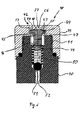
- Fig. 6 shows a sectional side view of a second nozzle according to the invention 38.
- the nozzle 38 corresponds in construction substantially to the nozzle 26. In this respect, reference is made to the comments on the nozzle 26. Similar to the nozzle 26 according to Fig. 5 also, the nozzle 38 has a housing 39 that is connected to a pressure piece 40 by means of a thread 41. Here, an internal thread of the housing 39 is in engagement with an external thread of the pressure piece 40.
- the nozzle 38 has a guide piece 42 which is composed of a first guide element 43 and a second guide element 44.
- the first guide element 43 is an integral part of the housing 39.
- the first Guide element 43 and the housing 39 are integrally formed in the embodiment shown here.
- the second guide element 44 is partially disposed within a bore 45 in the pressure piece 40.
- the second guide element 44 rests firmly against the first guide element 43 or the housing 39 on a first side, while resting on shoulders 46 of the pressure element 40 on a second side remote from the first guide element 43.
- the second guide element 44 has on its outer peripheral surface a plurality of uniformly spaced feed channels 47.
- the feed channels 47 merge into an annular first compensation chamber 53 formed by means of the first guide element 43.
- resulting rotational channels 54, 55 which direct the liquid with a nozzle outlet direction of the opposing component on a flat rotation base 48 of a rotary chamber 56.
- the rotation channels 54, 55 taper in the direction of the rotation chamber 56 or the rotation base 48.
- the rotation base 48 is arranged on the first side of the second guide element 44 facing away from the pressure piece 40.
- a further bore 49 is provided in the pressure piece 40, wherein the diameter of the further bore 49 is smaller than the diameter of the bore 45.
- a spring 50 is arranged is supported on the second guide member 44 and a ball 51 presses on an opening of a feed channel 52 for a liquid.
- the ball 51 is pressed against the force of the spring 50 from its seat in the direction of the second guide element 44. This allows the liquid to flow into the bore 49 and into the feed channels 47.
- a design with the spring 50 facilitates the assembly, since the guide element 44 so positioned itself during assembly.
- the liquid Via the first compensation chamber 53 integrated in the housing 39, the liquid enters the rotation chamber 56 by means of the rotation channels 54, 55, in order finally to exit from the nozzle 38 via the nozzle opening 57.
- Fig. 7 shows the second guide element 44 according to Fig. 6 in a perspective side view with the flat circular rotation base 48.
- a plurality of feed channels 58 are arranged close to each other. These feed channels 58 can be produced particularly easily as depressions or grooves.
- Fig. 8 is the second guide element 44 according to Fig. 6 and 7 can be seen in a further perspective side view, so that reference is also made in this regard to the above statements.
- the second guide element 44 consists of a first portion 59 and a second portion 60.
- the first portion 59 has a substantially circular cylindrical shape.
- two feed channels 61 arranged facing away from one another are provided on the outer circumferential surface of the first section 59, whose effective cross section or conductance is greater than the effective cross section or conductance of the feed channels 58 of the second section 60.
- the effective cross section or the conductance of the Feed channels 58 greater than the effective cross-section or conductance of the rotation channels 54, 55.
- the nozzle opening 57 in turn has a smaller effective cross-section or conductance than the rotation channels 54, 55 on. As a result, a sufficient fluid pressure and the supply of sufficient quantities of liquid is guaranteed.
- Fig. 8 the housing 39 according to Fig. 6 can be seen, wherein the nozzle opening is arranged in a protruding plateau 62.
- Fig. 9 shows the housing 39 according to Fig. 6 and 8th in a further perspective side view, so that the integrated in the housing 39 rotation channels 55 and a first portion of the rotation chamber 63 can be seen.
- Fig. 10 again shows a sectional side view of a nozzle 38 similar Fig. 6 , In this respect, reference is made to the corresponding statements. Compared to Fig. 10 reveals that Fig. 11 a further nozzle 64 according to the invention, whose structure is also substantially the same of the nozzle 38 according to Fig. 6 equivalent. In this respect, reference is made to the comments on the nozzle 38.
- the nozzles 38, 64 of Fig. 10,11 However, they have the projecting plateau 62.
- the nozzle 64 according to Fig. 11 differs from the nozzle 38 according to Fig. 10 a rotary chamber 65 which is composed of a circular cylindrical chamber space 66 facing the rotation base 48 and a conical comb taper 67 facing the nozzle opening 57.
- the rotary chamber 56 of the nozzle 38 after Fig. 10 only conical and has no circular cylindrical chamber space.
Landscapes
- Nozzles (AREA)
- Nozzles For Spraying Of Liquid Fuel (AREA)
Abstract
Description
- Die Erfindung betrifft eine Düse zum Zerstäuben einer Flüssigkeit mit einer Düsenöffnung, mit einer der Düsenöffnung vorgelagerten Rotationskammer, und mit mindestens einem tangential in die Rotationskammer einmündenden Rotationskanal zum Versetzen der Flüssigkeit in eine zur Düsenöffnung koaxiale Rotationsbewegung.
- Eine derartige Düse ist aus der
DE 101 38 622 C2 bekannt. Mittels dieser Düse bzw. dieses Zerstäubers wird Wasser zur Klimaverbesserung bei der Tierhaltung feinstvernebelt. Die erzeugten Nebeltröpfchen verdunsten, wodurch eine Kühlung der Raumluft erfolgt. Zudem wird durch die Anreicherung der Raumluft mit Wasser eine höhere Luftfeuchtigkeit erreicht. Der Zerstäuber wird mit dem üblichen und verhältnismäßig geringen Wasserleitungsdruck versorgt. Um eine bloße Benetzung der Umgebung mit Wasser zu vermeiden, ist es notwendig eine möglichst geringe Tröpfchengröße zu erreichen. Unter Berücksichtigung des geringen Wasserleitungsdruckes ist dies möglich, wenn das Wasser vor dem Vernebeln in eine Rotationsbewegung versetzt wird. Hierzu wird bei dem bekannten Zerstäuber das Wasser mittels Rotationskanälen von außen her tangential in eine Rotationskammer eingeleitet. Dabei wird das Wasser zunächst von außen auf eine umlaufende Bahn und im Weiteren nach innen und in Richtung auf die Düsenöffnung befördert. - Hierbei ist von Nachteil, dass nur eine bestimmte minimale Tröpfchengröße erreichbar ist. Dies kann zu einer nicht optimalen Effektivität des Zerstäubers beispielsweise bei der Klimatisierung, beim Ausfiltern von Staub- und/oder Schmutzpartikeln und/oder beim Einsatz im Brandschutz führen.
- Das der Erfindung zugrunde liegende Problem ist es, eine Düse der vorstehend genannten Art derart weiterzuentwickeln, dass eine geringere Tröpfchengröße erreichbar ist.
- Zur Lösung des der Erfindung zugrunde liegenden Problems wird eine Düse der vorstehend genannten Art angegeben, wobei die Flüssigkeit mit einer der Düsenaustrittsrichtung entgegen gerichteten Komponente in die Rotationskammer einleitbar ist.
- Hierbei ist von Vorteil, dass sich auf überraschend einfache Weise eine erheblich größere Rotationsgeschwindigkeit der Flüssigkeit beim Austritt aus der Düsenöffnung ergibt. Aufgrund dieser höheren Rotationsgeschwindigkeit entsteht an der Düsenöffnung eine kegelförmige Verteilung des Sprühnebels mit erheblich geringeren Tröpfchengrößen. Somit lässt sich auch unter Verwendung des verhältnismäßig geringen Wasserleitungsdruckes eine sehr feine Vernebelung des Wassers erreichen.
- Nach einer vorteilhaften Weiterbildung ist die in die Rotationskammer einströmende Flüssigkeit auf eine Rotationsbasis der Rotationskammer leitbar. Somit ist der in die Rotationskammer einmündende Rotationskanal einerseits mit einer Komponente entgegen der Düsenaustrittsrichtung und andererseits auf eine Rotationsbasis hin gerichtet. Aufgrund des tangential in die Rotationskammer einmündenden Rotationskanals bildet sich somit zunächst eine rotierende Fluid- bzw. Wasserscheibe auf der Rotationsbasis. Insbesondere wird die Flüssigkeit mittels des Rotationskanals fluchtend auf die Rotationsbasis geführt. Hierdurch werden die Entstehung einer turbulenzfreien Rotationsbewegung der Flüssigkeit begünstigt und unerwünschte Reibungsverluste reduziert. Vorteilhafterweise ist die Rotationsbasis der Düsenöffnung gegenüber angeordnet. Somit baut sich ausgehend von der Rotationsbasis in Richtung der Düsenöffnung eine rotierende Fluid- bzw. Wassersäule auf. Innerhalb der Wassersäule wirken auf die Moleküle geringere Reibungswiderstände als im Kontaktbereich zwischen der Wassersäule und der Wandung der Rotationskammer. Hierdurch kann sich innerhalb der Wassersäule eine größere Rotationsgeschwindigkeit als am Rand der Wassersäule einstellen.
- Vorteilhafterweise ist die Rotationsbasis als eine kegelförmige oder halbkugelförmige Vertiefung oder als eine flache Ebene ausgebildet. Dies begünstigt einerseits die Entstehung der rotierenden Wasserscheibe beziehungsweise Wassersäule und andererseits wird aufgrund des größeren Wasservolumens die Ausbildung einer höheren Rotationsgeschwindigkeit der Wassermoleküle innerhalb der Wassersäule gefördert.
- Entsprechend einer Weiterbildung weist ein stromaufwärts von der Düsenöffnung angeordnetes Leitstück den Rotationskanal auf. Die Verwendung eines separaten Leitstückes erlaubt einen modulartigen Aufbau der Düse. Dieses erleichtert die Herstellung und den Austausch einzelner Elemente bei einem Defekt. Vorteilhafterweise setzt sich das Leitstück aus einem ersten Leitelement und einem zweiten Leitelement zusammen. Dies erleichtert vor allem die Herstellung des Rotationskanals, der Rotationskammer und der Rotationsbasis. So kann das erste Leitelement die Düsenöffnung, den Rotationskanal und einen ersten Teilbereich der Rotationskammer aufweisen. Somit ist die Düsenöffnung als eine feine Durchgangsbohrung, der Rotationskanal als eine Vertiefungsrille und der erste Teilbereich der Rotationskammer als eine Einsenkung vergleichsweise einfach herstellbar. Das zweite Leitelement kann die Rotationsbasis als zweiten Teilbereich der Rotationskammer aufweisen. Hierbei kann die Rotationsbasis als eine flache Ebene oder eine kegelförmige oder halbkugelförmige Vertiefung ausgebildet sein, welches ebenfalls ohne größeren Aufwand leicht und somit kostengünstig herstellbar ist. Durch eine geeignete Anordnung des ersten und zweiten Leitelementes zueinander bildet sich das Leitstück, welches den Rotationskanal und die Rotationskammer aufweist.
- Nach einer Weiterbildung nimmt die Höhe der Rotationskammer zur Rotationsachse der Rotationsbewegung hin zu. Dies kann einerseits dadurch erfolgen, dass der erste Teilbereich der Rotationskammer im ersten Leitelement als eine kegelförmige oder als halbkugelförmige Vertiefung ausgebildet ist. Alternativ oder zusätzlich kann die Rotationsbasis als eine kegelförmige oder halbkugelförmige Vertiefung ausgebildet sein. Hierdurch bildet sich unterhalb der Düsenöffnung eine vergleichsweise hohe innere Wassersäule mit einer sehr hohen Rotationsgeschwindigkeit, wobei diese innere Wassersäule im Wesentlichen die Rotationsachse bildet. Auf die diese Rotationsachse bzw. innere Wassersäule umgebende ebenfalls rotierende äußere Wassersäule wirken nur sehr geringe Reibungswiderstände.
- Entsprechend einer weiteren Ausführungsform ist auf der von der Rotationskammer abgewandten Seite des ersten Leitelementes eine kegelförmige oder kegelstumpfförmige Einsenkung oder ein Plateau koaxial zur Düsenöffnung ausgebildet. Hierbei ist von Vorteil, dass durch diese Einsenkung ein zylindrischer Teil des Düsenkanals als Teil der Düsenöffnung vergleichsweise kurz gehalten wird, wodurch unnötige Reibung vermieden wird. Dennoch ergibt sich eine ausreichende Festigkeit und Widerstandsfähigkeit des ersten Leitelementes gegen den Druck der Flüssigkeit. Bei der Ausgestaltung mit dem Plateau lässt sich eine Tropfenbildung auf der die Düsenöffnung umgebenden Stirnfläche des Leitelementes durch den Sprühnebel wirkungsvoll unterdrücken
- Vorzugweise sind mehrere, insbesondere zwei oder vier, Rotationskanäle vorgesehen. Die Rotationskanäle werden derart zueinander angeordnet, dass die Flüssigkeit möglichst gleichmäßig von allen Seiten der Rotationskammer in diese eingeleitet wird. Hierbei ist vorzugsweise der Wirkquerschnitt des Rotationskanals oder die Summe der Wirkquerschnitte der Rotationskanäle gleich oder größer dem Wirkquerschnitt der Düsenöffnung. Bei gleichem Wirkquerschnitt bzw. Leitwert treten von den Rotationskanälen bis zur Düsenöffnung keine Druckdifferenzen auf. Eine Expansion der Flüssigkeit und damit einhergehender Turbulenzbildung findet erst beim Austritt der Flüssigkeit aus der Düsenöffnung statt. Weist der Rotationskanal einen wesentlich größeren Wirkquerschnitt bzw. Leitwert als die Düsenöffnung auf, wird hierdurch die Austrittsgeschwindigkeit der Flüssigkeit erhöht. Dadurch lässt sich die Flüssigkeit noch feiner vernebeln.
- Nach einer weiteren Ausführungsform nimmt ein Querschnitt des Rotationskanals von außen nach innen in Richtung der Rotationskammer, insbesondere in Bezug auf die Höhe und/oder die Breite des Rotationskanals ab. Hierdurch wird die Strömungsgeschwindigkeit der Flüssigkeit erhöht. Dies führt wiederum zu einer höheren Rotationsgeschwindigkeit der entstehenden Wassersäule, wodurch schließlich die Entstehung eines sehr feinen Sprühnebels begünstigt wird.
- Des Weiteren ist es von Vorteil, wenn die Düsenöffnung als ein Düsenkanal mit im Wesentlichen konstantem Wirkquerschnitt ausgebildet ist. Hierdurch wird ein rotierender Wasserzylinder, der im wesentlichen die Rotationsachse der gesamten rotierenden Wassersäule darstellt, aus dem Zentrum der Rotationskammer im wesentlichen laminar bis zum Austritt aus der Düsenöffnung geführt.
- Vorzugsweise entspricht die Länge des Düsenkanals dem Durchmesser der Düsenöffnung oder die Länge des Düsenkanals ist kleiner als der Durchmesser der Düsenöffnung. Hierdurch ergibt sich, insbesondere bei einer koaxial zur Düsenöffnung angeordneten kegelförmigen oder kegelstumpfförmigen Ausgestaltung des ersten Teilbereiches der Rotationskammer, eine besonders hohe Austrittsgeschwindigkeit der Flüssigkeit aus der Düsenöffnung. Hierbei wird mindestens ein Teil der Flüssigkeit von einem ersten der Rotationskammer zugewandten Bereich des Düsenkanals bzw. der Düsenöffnung zu einem diametral von der Rotationskammer und dem ersten Bereich abgewandten zweiten Bereich des Düsenkanals bzw. der Düsenöffnung geführt.
- Nach einer Weiterbildung weist das Leitstück dem Rotationskanal oder den Rotationskanälen jeweils über die volle axiale Länge des Leitstücks zugeordnete Speisekanäle auf. Durch die Speisekanäle ergibt sich eine einfach herzustellende Wasserversorgung für die Rotationskanäle. Vorzugsweise ist eine in dem Leitstück zwischen dem Rotationskanal und dem zugeordneten Speisekanal ausgebildete erste Ausgleichskammer vorgesehen. Hierdurch lassen sich Druckschwankungen und Geschwindigkeitsverluste durch turbulente Strömung einfach ausgleichen.
- Entsprechend einer weiteren Ausführungsform ist ein Druckstück zum Fixieren des Leitstückes vorgesehen. Hierbei ist von Vorteil, dass sich mittels dieses Druckstückes das Leitstück in einer vorbestimmten Position zu der Düsenöffnung fixieren lässt. Ein Sinterfilter kann die Funktion des Druckstückes übernehmen. Vorzugsweise weist das Druckstück mehrere den Speisekanälen jeweils zugeordnete Bohrungen auf und zwischen den Bohrungen und den Speisekanälen ist eine zweite Ausgleichskammer angeordnet. Die Zuführung des Fluids erfolgt hierbei im Wesentlichen kreisringförmig. Somit wird auch bei Fixierung des Leitstückes mit dem Druckstück eine ausreichende Wasserzufuhr ohne größeren Aufwand gewährleistet.
- Nach einer Weiterbildung ist ein Gehäuse zum Aufnehmen der Düse mit einem Innengewinde vorgesehen, wobei das Innengewinde mit einem Außengewinde des Druckstückes in Eingriff steht. Somit lässt sich die Düse durch einfaches Einlegen des Leitstückes in das Gehäuse und anschließendes Einschrauben des Druckstückes montieren. Vorzugsweise ist das Gehäuse und das Leitstück, insbesondere das erste Leitelement, einstückig hergestellt. Bei einer Materialverwendung von beispielsweise Edelstahl und/oder einem Edelstahl-Spritzgussverfahren lässt sich dieses kombinierte Bauteil auf einfache und günstige Weise herstellen. Hierdurch ist eine kostengünstige Düse herstellbar, die beispielsweise für den Brandschutz einsetzbar ist. Alternativ kann bei einer zweiteiligen Gestaltung von Gehäuse und Leitstück, insbesondere erstem Leitelement, das Leitstück und/oder das erste Leitelement aus Keramik hergestellt werden. Hierdurch ist eine erhöhte Abrasionsfestigkeit realisierbar. Somit wird eine dauerhafte Funktionstüchtigkeit auch bei einer dauerhaften und/oder regelmäßigen Verwendung der Düse, wie beispielsweise zum Klimatisieren und/oder zum Ausfiltern von Staub- und Schmutzpartikeln, gewährleistet.
- Von besonderem Vorteil ist die Verwendung der erfindungsgemäßen Düse zum Klimatisieren, zum Ausfiltern von Staub- und/oder Schmutzpartikeln und/oder für den Brandschutz.
- Im Folgenden wird ein Ausführungsbeispiel der Erfindung anhand der Zeichnungen näher erläutert. Es zeigen:
- Fig. 1
- eine perspektivische Draufsicht eines Leitelementes mit Merkmalen der erfindungsgemäßen Düse,
- Fig. 2
- eine perspektivische und geschnittene Seitendarstellung des Leitelementes gemäß
Fig. 1 , - Fig. 3
- eine perspektivische Draufsicht auf die Unterseite des Leitelementes gemäß
Fig.1 , - Fig. 4
- eine perspektivische und geschnittene Seitendarstellung eines Leitstückes mit einem Leitelement gemäß
Fig. 1 , - Fig. 5
- eine geschnittene Seitendarstellung einer erfindungsgemäßen Düse,
- Fig. 6
- eine geschnittene Seitendarstellung einer zweiten erfindungsgemäßen Düse,
- Fig. 7
- eine perspektivische Seitendarstellung eines zweiten Leitelementes,
- Fig. 8
- eine perspektivische Seitendarstellung des Leitelementes nach
Fig. 7 und ein weiteres Leitelement, - Fig. 9
- eine perspektivische Seitendarstellung des weiteren Leitelementes nach
Fig. 8 , - Fig. 10
- eine geschnittene Seitendarstellung der Düse nach
Fig. 6 und - Fig. 11
- eine geschnittene Seitendarstellung einer weiteren erfindungsgemäßen Düse.
-
Fig. 1 zeigt eine perspektivische Draufsicht auf ein Leitelement 10. Das Leitelement 10 ist im Wesentlichen zylinderförmig ausgebildet. Hierbei ist zentriert auf eine zylinderförmige Scheibe 19 ein Zylinder 20 mit im Vergleich zur Scheibe 19 geringeren Durchmesser angeordnet. Das Leitelement 10 lässt sich mittels einer Drehbank einstückig herstellen. Das Leitelement 10 weist mittig eine Düsenöffnung 11 auf. Die Düsenöffnung 11 ist als ein Düsenkanal 12 mit konstantem Wirkquerschnitt ausgebildet. - Der Zylinder 20 weist Rotationskanäle 13, 14 auf, die als Nuten beziehungsweise Einkerbungen ausgebildet sind. Die Rotationskanäle 13, 14 führen von außen kommend tangential in einen ersten Teilbereich einer Rotationskammer 15, wobei der erste Teilbereich der Rotationskammer 15 als eine im Wesentlichen kegelförmige Vertiefung um die Düsenöffnung 11 ausgebildet ist. Die Rotationskanäle 13, 14 sind derart ausgebildet, dass die Vertiefung von außen nach innen gehend, also in Richtung auf den ersten Teilbereich der Rotationskammer 15, abnimmt.
-
Fig. 2 zeigt eine perspektivische und geschnittene Seitendarstellung des Leitelementes 10 gemäßFig. 1 . Die kegelförmige Vertiefung, die den ersten Teilbereich der Rotationskammer 15 darstellt, besteht aus einer ersten Kammerwand 16 und einem Kammerkegel 17. Hierbei ist die Kammerwand 16 kegelstumpfförmig ausgebildet und weist einen geringeren Neigungswinkel als der Kammerkegel 17 auf. Die Höhe der Kammerwand 16 entspricht der Vertiefung der Rotationskanäle 13, 14 beim Übergang in den ersten Teilbereich der Rotationskammer 15. - Auf der von dem ersten Teilbereich der Rotationskammer 15 abgewandten Seite des Leitelementes 10 ist eine im Wesentlichen kegelförmige Einsenkung 18 koaxial zur Düsenöffnung 11 ausgebildet.
-
Fig. 3 zeigt eine Draufsicht auf die Unterseite des Leitelementes 10 gemäßFig. 1 . Die koaxial zur Düsenöffnung 11 ausgebildete kegelförmige Einsenkung 18 geht in eine flache ringscheibenförmige Ebene der Scheibe 19 über. -
Fig. 4 zeigt eine perspektivische und geschnittene Seitendarstellung eines Leitstückes 21 mit einem Leitelement 10 gemäßFig. 1 . Das Leitstück 21 besteht aus einem ersten Leitelement 10 und einem zweiten Leitelement 22. Das zweite Leitelement 22 ist als eine Scheibe ausgebildet und weist den gleichen Durchmesser wie die Scheibe 19 des ersten Leitelementes 10 auf. Das zweite Leitelement 22 ist derart dem ersten Leitelement zugeordnet, dass sich zwischen dem zweiten Leitelement 22 und der Scheibe 19 des ersten Leitelementes 10 eine gleichmäßig tiefe, umlaufende und U-förmige Nut ergibt. Innerhalb dieser Nut ist eine Dichtung 23 angeordnet, die hier als ein O-Ring ausgebildet ist. Gegenüber dem ersten Teilbereich der Rotationskammer 15 bildet das zweite Leitelement 22 eine ebene Rotationsbasis 24. Somit entsteht durch die Rotationsbasis 24 und den ersten Teilbereich der Rotationskammer 15 eine Rotationskammer 25. In die Rotationskammer 25 führt der Rotationskanal 13, dessen Querschnitt von außen nach innen gehend abnimmt. Der Rotationskanal 13 ist derart schräg in dem ersten Leitelement 10 angeordnet, dass das hierdurch fließende Fluid von außen nach innen und mit einer der Düsenaustrittsöffnung entgegen gerichteten Komponente in die Rotationskammer 25 eingeleitet wird. -
Fig. 5 zeigt eine geschnittene Seitendarstellung einer erfindungsgemäßen Düse 26, welche einen feinen Sprühnebel 27 erzeugt, wobei sich der Sprühnebel 27 ausgehend von der Düse 26 kegelförmig ausbreitet und bei dem gezeigten Ausführungsbeispiel einen Voll kegel bildet. Die Düse 26 weist ein Gehäuse 28 auf, wobei das Gehäuse 28 mit einem Druckstück 29 mittels eines Gewindes 30 verbunden ist. Hierbei steht ein Innengewinde des Gehäuses 28 mit einem Außengewinde des Druckstückes 29 in Eingriff. - Ein Leitstück 31 setzt sich aus einem ersten Leitelement 32 und einem zweiten Leitelement 33 zusammen. Hierbei ist das erste Leitelement 32 in dem Gehäuse 28 eingesetzt, während das zweite Leitelement 33 mittels des Druckstückes 29 in einer kreisscheibenförmigen Aufnahme des ersten Leitelementes 32 gehalten wird. Das zweite Leitelement 33 weist eine im Wesentlichen kreisscheibenförmige Gestalt auf, wobei an der Außenumfangsfläche des zweiten Leitelementes 33 mehrere gleichmäßig beabstandete Vertiefungen oder Rillen als Speisekanäle 34 vorgesehen sind. Die Speisekanäle 34 gehen in eine mittels des ersten Leitelementes 32 gebildete kreisringförmige erste Ausgleichskammer 36 über. Hiervon ausgehend ergeben sich Rotationskanäle 35, die die Flüssigkeit mit einer der Düsenaustrittsrichtung entgegen gerichteten Komponente auf eine ebene Rotationsbasis einer Rotationskammer 37 leiten. Hierbei verjüngen sich die Rotationskanäle 35 in Richtung auf die Rotationskammer 37 bzw. die Rotationsbasis.
-
Fig. 6 zeigt eine geschnittene Seitendarstellung einer zweiten erfindungsgemäßen Düse 38. Die Düse 38 entspricht im Aufbau im Wesentlichen der Düse 26. Insofern wird auf die Ausführungen zur Düse 26 verwiesen. Ähnlich wie die Düse 26 gemäßFig. 5 weist auch die Düse 38 ein Gehäuse 39 auf, dass mit einem Druckstück 40 mittels eines Gewindes 41 verbunden ist. Hierbei steht ein Innengewinde des Gehäuses 39 mit einem Außengewinde des Druckstückes 40 in Eingriff. - Die Düse 38 weist ein Leitstück 42 auf, welches sich aus einem ersten Leitelement 43 und einem zweiten Leitelement 44 zusammensetzt. Im Gegensatz zur Düse 26 ist hier das erste Leitelement 43 integraler Bestandteil des Gehäuses 39. Das erste Leitelement 43 und das Gehäuse 39 sind in dem hier gezeigten Ausführungsbeispiel einstückig ausgebildet.
- Das zweite Leitelement 44 ist teilweise innerhalb einer Bohrung 45 in dem Druckstück 40 angeordnet. Hierbei liegt das zweite Leitelement 44 auf einer ersten Seite fest an dem ersten Leitelement 43 bzw. dem Gehäuse 39 an, während es auf einer von dem ersten Leitelement 43 abgewandt liegenden zweiten Seite auf Schultern 46 des Druckstückes 40 aufliegt. Das zweite Leitelement 44 weist auf seiner Außenumfangsfläche mehrere gleichmäßig beabstandete Speisekanäle 47 auf. Die Speisekanäle 47 gehen in eine mittels des ersten Leitelementes 43 gebildete kreisringförmige erste Ausgleichskammer 53 über. Hiervon ausgehend ergeben sich Rotationskanäle 54, 55, die die Flüssigkeit mit einer der Düsenaustrittsrichtung entgegen gerichteten Komponente auf eine ebene Rotationsbasis 48 einer Rotationskammer 56 leiten. Hierbei verjüngen sich die Rotationskanäle 54, 55 in Richtung auf die Rotationskammer 56 bzw. die Rotationsbasis 48. Dabei ist die Rotationsbasis 48 an der von dem Druckstück 40 abgewandten ersten Seite des zweiten Leitelementes 44 angeordnet.
- An dem von der Rotationsbasis abgewandten Ende des zweiten Leitelementes 44 ist eine weitere Bohrung 49 in dem Druckstück 40 vorgesehen, wobei der Durchmesser der weiteren Bohrung 49 kleiner ist als der Durchmesser der Bohrung 45. Innerhalb der Bohrung 49 ist eine Feder 50 angeordnet, die sich an dem zweiten Leitelement 44 abstützt und eine Kugel 51 auf eine Öffnung eines Zuführkanals 52 für eine Flüssigkeit drückt.
- Sobald eine Flüssigkeit mit einem hinreichenden Druck in dem Zuführkanal 52 auf die Kugel 51 in Richtung der Düsenöffnung 57 drückt, wird die Kugel 51 gegen die Kraft der Feder 50 aus ihrem Sitz in Richtung des zweiten Leitelementes 44 gedrückt. Hierdurch kann die Flüssigkeit in die Bohrung 49 und in die Speisekanäle 47 fließen. Außerdem erleichtert eine Ausführung mit der Feder 50 die Montage, da sich das Leitelement 44 so bei der Montage selbst positioniert. Über die in dem Gehäuse 39 integrierte erste Ausgleichskammer 53 tritt die Flüssigkeit mittels der Rotationskanäle 54, 55 in die Rotationskammer 56 ein, um schließlich über die Düsenöffnung 57 aus der Düse 38 auszutreten.
-
Fig. 7 zeigt das zweite Leitelement 44 gemäßFig. 6 in einer perspektivischen Seitendarstellung mit der ebenen kreisförmigen Rotationsbasis 48. Insofern wird auf die vorstehenden Ausführungen verwiesen. Um die kreisförmige Außenumfangsfläche der Rotationsbasis 48 sind dicht nebeneinander liegend mehrere Speisekanäle 58 angeordnet. Diese Speisekanäle 58 lassen sich als Vertiefungen oder Rillen besonders einfach herstellen. -
Fig. 8 ist das zweite Leitelement 44 gemäßFig. 6 und7 in einer weiteren perspektivischen Seitendarstellung zu entnehmen, so dass auch diesbezüglich auf die vorstehenden Ausführungen verwiesen wird. Das zweite Leitelement 44 besteht aus einem ersten Abschnitt 59 und einem zweiten Abschnitt 60. Hierbei weist der erste Abschnitt 59 eine im Wesentlichen kreiszylinderförmige Gestalt auf. In dem gezeigten Ausführungsbeispiel sind an der Außenumfangsfläche des ersten Abschnitts 59 zwei voneinander abgewandt angeordnete Speisekanäle 61 vorgesehen, deren Wirkquerschnitt bzw. Leitwert größer ist als der Wirkquerschnitt bzw. Leitwert der Speisekanäle 58 des zweiten Abschnitts 60. Ferner ist der Wirkquerschnitt bzw. der Leitwert der Speisekanäle 58 größer als der Wirkquerschnitt bzw. Leitwert der Rotationskanäle 54, 55. Die Düsenöffnung 57 wiederum weist einen kleineren Wirkquerschnitt bzw. Leitwert als die Rotationskanäle 54, 55 auf. Hierdurch ist ein hinreichender Flüssigkeitsdruck und die Zuführung ausreichender Flüssigkeitsmengen gewährleistet. Weiter ist derFig. 8 das Gehäuse 39 gemäßFig. 6 zu entnehmen, wobei die Düsenöffnung in einem vorstehenden Plateau 62 angeordnet ist. -
Fig. 9 zeigt das Gehäuse 39 gemäßFig. 6 und8 in einer weiteren perspektivischen Seitendarstellung, so dass die in dem Gehäuse 39 integrierten Rotationskanäle 55 und ein erster Teilbereich der Rotationskammer 63 erkennbar ist. -
Fig. 10 zeigt noch einmal eine geschnittene Seitendarstellung einer Düse 38 ähnlichFig. 6 . Insofern wird auf die entsprechenden Ausführungen verwiesen. Im Vergleich zuFig. 10 offenbart dieFig. 11 eine weitere erfindungsgemäße Düse 64, deren Aufbau ebenfalls im Wesentlichen dem der Düse 38 gemäßFig. 6 entspricht. Insofern wird auf die Ausführungen zur Düse 38 verwiesen. Die Düsen 38, 64 vonFig. 10,11 weisen jedoch das vorstehende Plateau 62 auf. - Die Düse 64 gemäß
Fig. 11 weist abweichend zur Düse 38 gemäßFig. 10 eine Rotationskammer 65 auf, die sich aus einem der Rotationsbasis 48 zugewandten kreiszylinderförmigen Kammerraum 66 und einem der Düsenöffnung 57 zugewandten kegelförmigen Kammkegel 67 zusammensetzt. Dagegen ist die Rotationskammer 56 der Düse 38 nachFig. 10 nur kegelförmig ausgebildet und weist keinen kreiszylinderförmigen Kammerraum auf. - Aufgrund des Kammerraumes 66 bei der Düse 38 gemäß
Fig. 11 bildet sich eine besonders stabile Flüssigkeitssäule in der Rotationskammer 65 aus. Hierdurch wird die Rotationsgeschwindigkeit erhöht, Reibungsverluste werden reduziert und die Austrittsgeschwindigkeit aus der Düsenöffnung 57 wird erhöht. Dies führt zu einem noch feineren Sprühnebel mit sehr geringer Tröpfchengrößen. - Die Funktionsweise der erfindungsgemäßen Düse wird im Folgenden anhand der
Fig. 1 bis 11 näher erläutert: - Als ein Fluid gelangt beispielsweise Wasser mit dem üblichen Druck aus Wasserleitungen durch nicht näher dargestellte Bohrungen eines Druckstückes zu dem ersten Leitelement 10, 32, 43. Mittels der Rotationskanäle 13, 14, 35, 54, 55 wird das Wasser von außen her tangential in die Rotationskammer 25, 37, 56, 65 eingeleitet. Hierbei wird das Wasser von außen auf einer umlaufenden Bahn nach innen und entgegen der Düsenaustrittsöffnung auf die Rotationsbasis 24, 48 geleitet. Auf der Rotationsbasis 24, 48 bildet sich eine rotierende Wasserscheibe, welche sich mit zunehmender Wassermenge in Richtung auf die Düsenöffnung 11, 57 als eine rotierende Wassersäule ausbildet. Die Wassermoleküle innerhalb der rotierenden Wassersäule im Bereich der Rotationsachse erreichen eine maximale Rotationsgeschwindigkeit. Hierbei ist der Einfluss des Reibungswiderstandes zwischen der Rotationsbasis 24, 48, der Kammerwand 16, der Wand des Kammerraumes 66 und des Kammerkegels 17, 67 einerseits sowie der Wassersäule im Bereich der Rotationsachse andererseits erheblich reduziert. Somit tritt das Wasser mit einer maximalen Rotationsgeschwindigkeit aus der Düsenöffnung 11, 57 aus. Die an der Düsenöffnung 11, 57 frei werdende Zentrifugalkraft führt zu einer kegelförmigen Verteilung eines Sprühnebels mit sehr geringen Tröpfchengrößen. Somit lässt sich auch unter Verwendung eines verhältnismäßig geringen Wasserleitungsdruckes eine sehr feine Vernebelung erreichen.
- Dieser sehr feine Nebel kann sowohl zur Klimatisierung in der Tierhaltung als auch zum Ausfiltern von Staub- und/oder Schmutzpartikeln genutzt werden. Des weiteren kann die erfindungsgemäße Düse auch im Bereich des Brandschutzes eingesetzt werden. Hierbei ist im Vergleich zu üblichen Sprinkleranlagen von besonderem Vorteil, dass durch den feinen Sprühnebel nicht nur das Feuer erstickt beziehungsweise gelöscht wird, sondern zugleich Ruß- und Schmutzpartikel aus der Luft ausgefiltert werden. Zudem wird eine Beschädigung von Gegenständen durch einen übermäßigen Flüssigkeitseintrag vermieden. Der Löschwasserschaden kann somit weitgehend vermieden werden.
-
- 10
- Leitelement
- 11
- Düsenöffnung
- 12
- Düsenkanal
- 13
- Rotationskanal
- 14
- Rotationskanal
- 15
- erster Teilbereich der Rotationskammer
- 16
- Kammerwand
- 17
- Kammerkegel
- 18
- Einsenkung
- 19
- Scheibe
- 20
- Zylinder
- 21
- Leitstück
- 22
- Leitelement
- 23
- Dichtung
- 24
- Rotationsbasis
- 25
- Rotationskammer
- 26
- Düse
- 27
- Sprühnebel
- 28
- Gehäuse
- 29
- Druckstück
- 30
- Gewinde
- 31
- Leitstück
- 32
- erstes Leitelement
- 33
- zweites Leitelement
- 34
- Speisekanal
- 35
- Rotationskanal
- 36
- erste Ausgleichskammer
- 37
- Rotationskammer
- 38
- Düse
- 39
- Gehäuse
- 40
- Druckstück
- 41
- Gewinde
- 42
- Leitstück
- 43
- erstes Leitelement
- 44
- zweites Leitelement
- 45
- Bohrung
- 46
- Schulter
- 47
- Speisekanal
- 48
- Rotationsbasis
- 49
- Bohrung
- 50
- Feder
- 51
- Kugel
- 52
- Zuführkanal
- 53
- erste Ausgleichskammer
- 54
- Rotationskanal
- 55
- Rotationskanal
- 56
- Rotationskammer
- 57
- Düsenöffnung
- 58
- Speisekanal
- 59
- erster Abschnitt
- 60
- zweiter Abschnitt
- 61
- Speisekanal
- 62
- Plateau
- 63
- erster Teilbereich der Rotationskammer
- 64
- Düse
- 65
- Rotationskammer
- 66
- Kammerraum
- 67
- Kammerkegel
Claims (15)
- Düse zum Zerstäuben einer Flüssigkeit mit einer Düsenöffnung (11, 57), mit einer der Düsenöffnung (11, 57) vorgelagerten Rotationskammer (25, 37, 56, 65), und mit mindestens einem tangential in die Rotationskammer (25, 37, 56, 65) einmündenden Rotationskanal (13, 14, 35, 54, 55) zum Versetzen der Flüssigkeit in eine zur Düsenöffnung (11, 57) koaxiale Rotationsbewegung, dadurch gekennzeichnet, dass die Flüssigkeit mit einer der Düsenaustrittsrichtung entgegen gerichteten Komponente in die Rotationskammer (25, 37, 56, 65) einleitbar ist.
- Düse nach Anspruch 1, dadurch gekennzeichnet, dass die in die Rotationskammer (25, 37, 56, 65) einströmende Flüssigkeit auf eine Rotationsbasis (24, 48) der Rotationskammer (25, 37, 56, 65) leitbar ist, wobei vorzugsweise die Rotationsbasis (24, 48) der Düsenöffnung (11, 57) gegenüber angeordnet ist und/oder die Rotationsbasis (24, 48) als eine kegelförmige oder halbkugelförmige Vertiefung oder als eine flache Ebene ausgebildet ist.
- Düse nach Anspruch 1 oder 2, dadurch gekennzeichnet, dass ein stromaufwärts von der Düsenöffnung (11, 57) angeordnetes Leitstück (21, 31, 42) den Rotationskanal (13, 14, 35, 54, 55) aufweist, wobei sich vorzugsweise das Leitstück (21, 31, 42) aus einem ersten Leitelement (10, 32, 43) und einem zweiten Leitelement (22, 33, 44) zusammensetzt.
- Düse nach Anspruch 3, dadurch gekennzeichnet, dass das erste Leitelement (10, 32, 43) die Düsenöffnung (11, 57), den Rotationskanal (13, 14, 35, 54, 55) und einen ersten Teilbereich der Rotationskammer (15, 63) aufweist und/oder das zweite Leitelement (22, 33, 44) die Rotationsbasis (24, 48) als zweiten Teilbereich der Rotationskammer (25, 37, 56, 65) aufweist.
- Düse nach einem der vorhergehenden Ansprüche, dadurch gekennzeichnet, dass die Höhe der Rotationskammer (25, 37, 56, 65) zur Rotationsachse der Rotationsbewegung hin zunimmt.
- Düse nach einem der Ansprüche 3 bis 5, dadurch gekennzeichnet, dass auf der von der Rotationskammer (25, 37, 56, 65) abgewandten Seite des ersten Leitelementes (10, 32, 43) eine kegelförmige oder kegelstumpfförmige Einsenkung (18) oder ein Plateau (62) koaxial zur Düsenöffnung (11, 57) ausgebildet ist.
- Düse nach einem der vorhergehenden Ansprüche, dadurch gekennzeichnet, dass mehrere, insbesondere zwei oder vier, Rotationskanäle (13, 14, 35, 54, 55) vorgesehen sind.
- Düse nach einem der vorhergehenden Ansprüche, dadurch gekennzeichnet, dass der Wirkquerschnitt des Rotationskanals (13, 14, 35, 54, 55) oder die Summe der Wirkquerschnitte der Rotationskanäle (13, 14, 35, 54, 55) gleich oder größer dem Wirkquerschnitt der Düsenöffnung (11, 57) ist.
- Düse nach einem der vorhergehenden Ansprüche, dadurch gekennzeichnet, dass ein Querschnitt des Rotationskanals (13, 14, 35, 54, 55) von außen nach innen in Richtung der Rotationskammer (25, 37, 56, 65), insbesondere gleichmäßig in Bezug auf die Höhe und/oder die Breite des Rotationskanals (13, 14, 35, 54, 55), abnimmt.
- Düse nach einem der vorhergehenden Ansprüche, dadurch gekennzeichnet, dass die Düsenöffnung (11, 57) als ein Düsenkanal (12) mit im Wesentlichen konstantem Wirkquerschnitt ausgebildet ist.
- Düse nach einem der vorhergehenden Ansprüche, dadurch gekennzeichnet, dass die Länge des Düsenkanals (12) dem Durchmesser der Düsenöffnung (11, 57) entspricht oder die Länge des Düsenkanals (12) ist kleiner als der Durchmesser der Düsenöffnung (11, 57).
- Düse nach einem der Ansprüche 3 bis 11, dadurch gekennzeichnet, dass das Leitstück dem Rotationskanal (13, 14, 35, 54, 55) oder den Rotationskanälen (13, 14, 35, 54, 55) jeweils über die volle axiale Länge des Leitstücks (21, 31, 42) zugeordnete Speisekanäle (34, 47, 58, 61) aufweist, wobei vorzugsweise eine in dem Leitstück (21, 31, 42) zwischen dem Rotationskanal (13, 14, 35, 54, 55) und dem zugeordneten Speisekanal (34, 47, 58, 61) ausgebildete erste Ausgleichskammer (36, 53) vorgesehen ist.
- Düse nach einem der Ansprüche 3 bis 12, dadurch gekennzeichnet, dass ein Druckstück (29, 40) zum Fixieren des Leitstückes (21, 31, 42) vorgesehen ist, wobei vorzugsweise das Druckstück (29, 40) mehrere den Speisekanälen (34, 47, 58, 61) jeweils zugeordnete Bohrungen (45, 49, 52) aufweist, und dass zwischen den Bohrungen (45, 49, 52) und den Speisekanälen (34, 47, 58, 61) eine zweite Ausgleichskammer angeordnet ist.
- Düse nach Anspruch 13, dadurch gekennzeichnet, dass ein Gehäuse (28, 39) zum Aufnehmen der Düse mit einem Innengewinde vorgesehen ist, wobei das Innengewinde mit einem Außengewinde des Druckstückes (29, 40) in Eingriff steht.
- Verwendung einer Düse nach einem der vorhergehenden Ansprüche zum Klimatisieren, zum Ausfiltern von Staub- und/oder Schmutzpartikeln und/oder für den Brandschutz.
Applications Claiming Priority (1)
| Application Number | Priority Date | Filing Date | Title |
|---|---|---|---|
| DE102008017913A DE102008017913A1 (de) | 2008-04-08 | 2008-04-08 | Düse zum Zerstäuben einer Flüssigkeit |
Publications (2)
| Publication Number | Publication Date |
|---|---|
| EP2108459A1 true EP2108459A1 (de) | 2009-10-14 |
| EP2108459B1 EP2108459B1 (de) | 2010-06-02 |
Family
ID=40666829
Family Applications (1)
| Application Number | Title | Priority Date | Filing Date |
|---|---|---|---|
| EP09157562A Active EP2108459B1 (de) | 2008-04-08 | 2009-04-07 | Düse zum Zerstäuben einer Flüssigkeit |
Country Status (3)
| Country | Link |
|---|---|
| EP (1) | EP2108459B1 (de) |
| AT (1) | ATE469702T1 (de) |
| DE (2) | DE102008017913A1 (de) |
Cited By (2)
| Publication number | Priority date | Publication date | Assignee | Title |
|---|---|---|---|---|
| WO2018229177A1 (de) * | 2017-06-15 | 2018-12-20 | Alfons Kenter | Zerstäuberdüse |
| CN116921081A (zh) * | 2022-04-08 | 2023-10-24 | 芜湖美的厨卫电器制造有限公司 | 喷头及沐浴设备 |
Citations (4)
| Publication number | Priority date | Publication date | Assignee | Title |
|---|---|---|---|---|
| US2140903A (en) | 1936-06-20 | 1938-12-20 | Merton L Fisk | Spraying nozzle |
| DE1500594B1 (de) * | 1964-08-07 | 1970-04-30 | Spraying Systems Co | Spruehduese mit Wirbelkammer zur Herstellung eines hohlkegeligen Spruehstrahls |
| EP0924460A1 (de) * | 1997-12-22 | 1999-06-23 | Abb Research Ltd. | Zweistufige Druckzerstäuberdüse |
| DE10138622A1 (de) * | 2001-08-13 | 2003-03-06 | Alfons Kenter | Zerstäuber zum Vernebeln einer Flüssigkeit |
Family Cites Families (1)
| Publication number | Priority date | Publication date | Assignee | Title |
|---|---|---|---|---|
| DE10208223A1 (de) * | 2002-02-26 | 2003-10-30 | Bosch Gmbh Robert | Brennstoffeinspritzventil |
-
2008
- 2008-04-08 DE DE102008017913A patent/DE102008017913A1/de not_active Ceased
-
2009
- 2009-04-07 EP EP09157562A patent/EP2108459B1/de active Active
- 2009-04-07 AT AT09157562T patent/ATE469702T1/de active
- 2009-04-07 DE DE502009000024T patent/DE502009000024D1/de active Active
Patent Citations (5)
| Publication number | Priority date | Publication date | Assignee | Title |
|---|---|---|---|---|
| US2140903A (en) | 1936-06-20 | 1938-12-20 | Merton L Fisk | Spraying nozzle |
| DE1500594B1 (de) * | 1964-08-07 | 1970-04-30 | Spraying Systems Co | Spruehduese mit Wirbelkammer zur Herstellung eines hohlkegeligen Spruehstrahls |
| EP0924460A1 (de) * | 1997-12-22 | 1999-06-23 | Abb Research Ltd. | Zweistufige Druckzerstäuberdüse |
| DE10138622A1 (de) * | 2001-08-13 | 2003-03-06 | Alfons Kenter | Zerstäuber zum Vernebeln einer Flüssigkeit |
| DE10138622C2 (de) | 2001-08-13 | 2003-06-18 | Alfons Kenter | Zerstäuber zum Vernebeln einer Flüssigkeit |
Cited By (5)
| Publication number | Priority date | Publication date | Assignee | Title |
|---|---|---|---|---|
| WO2018229177A1 (de) * | 2017-06-15 | 2018-12-20 | Alfons Kenter | Zerstäuberdüse |
| CN110997155A (zh) * | 2017-06-15 | 2020-04-10 | A·肯特尔 | 一种雾化器喷嘴 |
| CN110997155B (zh) * | 2017-06-15 | 2021-10-26 | A·肯特尔 | 一种雾化器喷嘴 |
| US11712706B2 (en) | 2017-06-15 | 2023-08-01 | Alfons Kenter | Atomizer nozzle |
| CN116921081A (zh) * | 2022-04-08 | 2023-10-24 | 芜湖美的厨卫电器制造有限公司 | 喷头及沐浴设备 |
Also Published As
| Publication number | Publication date |
|---|---|
| DE502009000024D1 (de) | 2010-07-15 |
| ATE469702T1 (de) | 2010-06-15 |
| DE102008017913A1 (de) | 2009-10-15 |
| EP2108459B1 (de) | 2010-06-02 |
Similar Documents
| Publication | Publication Date | Title |
|---|---|---|
| DE10304386B4 (de) | Doppelfluid-Verwirbelungsdüse mit selbstreinigendem Zapfen | |
| EP2969234B1 (de) | Zerstäuberdüse für einen sanitären wasserauslauf sowie sanitäre auslaufarmatur mit einem wasserauslauf | |
| EP0710506B1 (de) | Düsenanordnung für eine Farbspritzpistole | |
| WO1991016989A1 (de) | Rotordüse für ein hochdruckreinigungsgerät | |
| DE112006002295T5 (de) | Sprühdüsenanordnung zur Atomisierung mittels externer Luftmischung | |
| EP1136133B1 (de) | Reinigungsdüse | |
| WO2003015929A1 (de) | Dralldruck-düse | |
| DE202019102106U1 (de) | Keramikteil für einen Laserbearbeitungskopf zur Kühlung des Werkstücks | |
| EP3302815B1 (de) | Drallkörper sowie kegeldüse mit einem solchen drallkörper | |
| EP2108459B1 (de) | Düse zum Zerstäuben einer Flüssigkeit | |
| EP2251091A2 (de) | Rotordüse | |
| DE102006053625A1 (de) | Rotordüse | |
| DE10138622C2 (de) | Zerstäuber zum Vernebeln einer Flüssigkeit | |
| EP1905470A2 (de) | Inhalationsvorrichtung | |
| DE102005056006B4 (de) | Pulverfördervorrichtung und Fangdüse für die Pulverfördervorrichtung | |
| DE3537906A1 (de) | Zyklon-abscheider | |
| DE19918120A1 (de) | Zerstäuberdüse | |
| CH717897A2 (de) | Ventileinrichtung für ein gesteuertes Durchlassen eines Mediums insbesondere im Hochdruckbereich. | |
| EP3638424B1 (de) | Zerstäuberdüse | |
| AT507662B1 (de) | Sprühdüse | |
| DE29802025U1 (de) | Hochdruckzerstäuber | |
| EP0246220B1 (de) | Einspritzdüse für Brennkraftmaschinen, insbesondere Dieselmotoren | |
| DE102013002235A1 (de) | Luftansaugvorrichtung für eine Sanitärbrause | |
| DE102005029687B4 (de) | Spritzvorrichtung und Spritzkopf | |
| EP4129489B1 (de) | Flachstrahldüse |
Legal Events
| Date | Code | Title | Description |
|---|---|---|---|
| PUAI | Public reference made under article 153(3) epc to a published international application that has entered the european phase |
Free format text: ORIGINAL CODE: 0009012 |
|
| 17P | Request for examination filed |
Effective date: 20090727 |
|
| AK | Designated contracting states |
Kind code of ref document: A1 Designated state(s): AT BE BG CH CY CZ DE DK EE ES FI FR GB GR HR HU IE IS IT LI LT LU LV MC MK MT NL NO PL PT RO SE SI SK TR |
|
| GRAP | Despatch of communication of intention to grant a patent |
Free format text: ORIGINAL CODE: EPIDOSNIGR1 |
|
| GRAS | Grant fee paid |
Free format text: ORIGINAL CODE: EPIDOSNIGR3 |
|
| GRAA | (expected) grant |
Free format text: ORIGINAL CODE: 0009210 |
|
| AK | Designated contracting states |
Kind code of ref document: B1 Designated state(s): AT BE BG CH CY CZ DE DK EE ES FI FR GB GR HR HU IE IS IT LI LT LU LV MC MK MT NL NO PL PT RO SE SI SK TR |
|
| REG | Reference to a national code |
Ref country code: GB Ref legal event code: FG4D Free format text: NOT ENGLISH |
|
| REG | Reference to a national code |
Ref country code: CH Ref legal event code: EP |
|
| REG | Reference to a national code |
Ref country code: IE Ref legal event code: FG4D Free format text: LANGUAGE OF EP DOCUMENT: GERMAN |
|
| REF | Corresponds to: |
Ref document number: 502009000024 Country of ref document: DE Date of ref document: 20100715 Kind code of ref document: P |
|
| REG | Reference to a national code |
Ref country code: NL Ref legal event code: T3 |
|
| PG25 | Lapsed in a contracting state [announced via postgrant information from national office to epo] |
Ref country code: LT Free format text: LAPSE BECAUSE OF FAILURE TO SUBMIT A TRANSLATION OF THE DESCRIPTION OR TO PAY THE FEE WITHIN THE PRESCRIBED TIME-LIMIT Effective date: 20100602 Ref country code: NO Free format text: LAPSE BECAUSE OF FAILURE TO SUBMIT A TRANSLATION OF THE DESCRIPTION OR TO PAY THE FEE WITHIN THE PRESCRIBED TIME-LIMIT Effective date: 20100902 Ref country code: SE Free format text: LAPSE BECAUSE OF FAILURE TO SUBMIT A TRANSLATION OF THE DESCRIPTION OR TO PAY THE FEE WITHIN THE PRESCRIBED TIME-LIMIT Effective date: 20100602 |
|
| LTIE | Lt: invalidation of european patent or patent extension |
Effective date: 20100602 |
|
| PG25 | Lapsed in a contracting state [announced via postgrant information from national office to epo] |
Ref country code: SI Free format text: LAPSE BECAUSE OF FAILURE TO SUBMIT A TRANSLATION OF THE DESCRIPTION OR TO PAY THE FEE WITHIN THE PRESCRIBED TIME-LIMIT Effective date: 20100602 Ref country code: LV Free format text: LAPSE BECAUSE OF FAILURE TO SUBMIT A TRANSLATION OF THE DESCRIPTION OR TO PAY THE FEE WITHIN THE PRESCRIBED TIME-LIMIT Effective date: 20100602 Ref country code: FI Free format text: LAPSE BECAUSE OF FAILURE TO SUBMIT A TRANSLATION OF THE DESCRIPTION OR TO PAY THE FEE WITHIN THE PRESCRIBED TIME-LIMIT Effective date: 20100602 Ref country code: HR Free format text: LAPSE BECAUSE OF FAILURE TO SUBMIT A TRANSLATION OF THE DESCRIPTION OR TO PAY THE FEE WITHIN THE PRESCRIBED TIME-LIMIT Effective date: 20100602 |
|
| PG25 | Lapsed in a contracting state [announced via postgrant information from national office to epo] |
Ref country code: CY Free format text: LAPSE BECAUSE OF FAILURE TO SUBMIT A TRANSLATION OF THE DESCRIPTION OR TO PAY THE FEE WITHIN THE PRESCRIBED TIME-LIMIT Effective date: 20100616 Ref country code: PL Free format text: LAPSE BECAUSE OF FAILURE TO SUBMIT A TRANSLATION OF THE DESCRIPTION OR TO PAY THE FEE WITHIN THE PRESCRIBED TIME-LIMIT Effective date: 20100602 |
|
| REG | Reference to a national code |
Ref country code: IE Ref legal event code: FD4D |
|
| PG25 | Lapsed in a contracting state [announced via postgrant information from national office to epo] |
Ref country code: EE Free format text: LAPSE BECAUSE OF FAILURE TO SUBMIT A TRANSLATION OF THE DESCRIPTION OR TO PAY THE FEE WITHIN THE PRESCRIBED TIME-LIMIT Effective date: 20100602 Ref country code: IE Free format text: LAPSE BECAUSE OF FAILURE TO SUBMIT A TRANSLATION OF THE DESCRIPTION OR TO PAY THE FEE WITHIN THE PRESCRIBED TIME-LIMIT Effective date: 20100602 |
|
| PG25 | Lapsed in a contracting state [announced via postgrant information from national office to epo] |
Ref country code: SK Free format text: LAPSE BECAUSE OF FAILURE TO SUBMIT A TRANSLATION OF THE DESCRIPTION OR TO PAY THE FEE WITHIN THE PRESCRIBED TIME-LIMIT Effective date: 20100602 Ref country code: RO Free format text: LAPSE BECAUSE OF FAILURE TO SUBMIT A TRANSLATION OF THE DESCRIPTION OR TO PAY THE FEE WITHIN THE PRESCRIBED TIME-LIMIT Effective date: 20100602 Ref country code: CZ Free format text: LAPSE BECAUSE OF FAILURE TO SUBMIT A TRANSLATION OF THE DESCRIPTION OR TO PAY THE FEE WITHIN THE PRESCRIBED TIME-LIMIT Effective date: 20100602 Ref country code: IS Free format text: LAPSE BECAUSE OF FAILURE TO SUBMIT A TRANSLATION OF THE DESCRIPTION OR TO PAY THE FEE WITHIN THE PRESCRIBED TIME-LIMIT Effective date: 20101002 |
|
| PG25 | Lapsed in a contracting state [announced via postgrant information from national office to epo] |
Ref country code: IT Free format text: LAPSE BECAUSE OF FAILURE TO SUBMIT A TRANSLATION OF THE DESCRIPTION OR TO PAY THE FEE WITHIN THE PRESCRIBED TIME-LIMIT Effective date: 20100602 |
|
| PLBE | No opposition filed within time limit |
Free format text: ORIGINAL CODE: 0009261 |
|
| STAA | Information on the status of an ep patent application or granted ep patent |
Free format text: STATUS: NO OPPOSITION FILED WITHIN TIME LIMIT |
|
| PG25 | Lapsed in a contracting state [announced via postgrant information from national office to epo] |
Ref country code: DK Free format text: LAPSE BECAUSE OF FAILURE TO SUBMIT A TRANSLATION OF THE DESCRIPTION OR TO PAY THE FEE WITHIN THE PRESCRIBED TIME-LIMIT Effective date: 20100602 |
|
| 26N | No opposition filed |
Effective date: 20110303 |
|
| PG25 | Lapsed in a contracting state [announced via postgrant information from national office to epo] |
Ref country code: GR Free format text: LAPSE BECAUSE OF FAILURE TO SUBMIT A TRANSLATION OF THE DESCRIPTION OR TO PAY THE FEE WITHIN THE PRESCRIBED TIME-LIMIT Effective date: 20100903 |
|
| REG | Reference to a national code |
Ref country code: DE Ref legal event code: R097 Ref document number: 502009000024 Country of ref document: DE Effective date: 20110302 |
|
| PG25 | Lapsed in a contracting state [announced via postgrant information from national office to epo] |
Ref country code: MC Free format text: LAPSE BECAUSE OF NON-PAYMENT OF DUE FEES Effective date: 20110430 |
|
| PG25 | Lapsed in a contracting state [announced via postgrant information from national office to epo] |
Ref country code: MT Free format text: LAPSE BECAUSE OF FAILURE TO SUBMIT A TRANSLATION OF THE DESCRIPTION OR TO PAY THE FEE WITHIN THE PRESCRIBED TIME-LIMIT Effective date: 20100602 |
|
| REG | Reference to a national code |
Ref country code: DE Ref legal event code: R082 Ref document number: 502009000024 Country of ref document: DE Representative=s name: JABBUSCH SIEKMANN & WASILJEFF, DE Ref country code: DE Ref legal event code: R082 Ref document number: 502009000024 Country of ref document: DE Representative=s name: PATENTANWAELTE JABBUSCH SIEKMANN & WASILJEFF, DE |
|
| PG25 | Lapsed in a contracting state [announced via postgrant information from national office to epo] |
Ref country code: LU Free format text: LAPSE BECAUSE OF NON-PAYMENT OF DUE FEES Effective date: 20110407 |
|
| PG25 | Lapsed in a contracting state [announced via postgrant information from national office to epo] |
Ref country code: PT Free format text: LAPSE BECAUSE OF NON-PAYMENT OF DUE FEES Effective date: 20100602 |
|
| PG25 | Lapsed in a contracting state [announced via postgrant information from national office to epo] |
Ref country code: TR Free format text: LAPSE BECAUSE OF FAILURE TO SUBMIT A TRANSLATION OF THE DESCRIPTION OR TO PAY THE FEE WITHIN THE PRESCRIBED TIME-LIMIT Effective date: 20100602 Ref country code: BG Free format text: LAPSE BECAUSE OF FAILURE TO SUBMIT A TRANSLATION OF THE DESCRIPTION OR TO PAY THE FEE WITHIN THE PRESCRIBED TIME-LIMIT Effective date: 20100902 |
|
| PG25 | Lapsed in a contracting state [announced via postgrant information from national office to epo] |
Ref country code: HU Free format text: LAPSE BECAUSE OF FAILURE TO SUBMIT A TRANSLATION OF THE DESCRIPTION OR TO PAY THE FEE WITHIN THE PRESCRIBED TIME-LIMIT Effective date: 20100602 Ref country code: ES Free format text: LAPSE BECAUSE OF FAILURE TO SUBMIT A TRANSLATION OF THE DESCRIPTION OR TO PAY THE FEE WITHIN THE PRESCRIBED TIME-LIMIT Effective date: 20100913 |
|
| REG | Reference to a national code |
Ref country code: DE Ref legal event code: R082 Ref document number: 502009000024 Country of ref document: DE Representative=s name: JABBUSCH SIEKMANN & WASILJEFF, DE Ref country code: DE Ref legal event code: R082 Ref document number: 502009000024 Country of ref document: DE Representative=s name: PATENTANWAELTE JABBUSCH SIEKMANN & WASILJEFF, DE |
|
| REG | Reference to a national code |
Ref country code: FR Ref legal event code: PLFP Year of fee payment: 7 |
|
| REG | Reference to a national code |
Ref country code: FR Ref legal event code: PLFP Year of fee payment: 8 |
|
| REG | Reference to a national code |
Ref country code: FR Ref legal event code: PLFP Year of fee payment: 9 |
|
| REG | Reference to a national code |
Ref country code: DE Ref legal event code: R008 Ref document number: 502009000024 Country of ref document: DE Ref country code: DE Ref legal event code: R039 Ref document number: 502009000024 Country of ref document: DE |
|
| REG | Reference to a national code |
Ref country code: FR Ref legal event code: PLFP Year of fee payment: 10 |
|
| REG | Reference to a national code |
Ref country code: DE Ref legal event code: R040 Ref document number: 502009000024 Country of ref document: DE |
|
| PGFP | Annual fee paid to national office [announced via postgrant information from national office to epo] |
Ref country code: NL Payment date: 20250422 Year of fee payment: 17 |
|
| PGFP | Annual fee paid to national office [announced via postgrant information from national office to epo] |
Ref country code: DE Payment date: 20250415 Year of fee payment: 17 |
|
| PGFP | Annual fee paid to national office [announced via postgrant information from national office to epo] |
Ref country code: GB Payment date: 20250423 Year of fee payment: 17 |
|
| PGFP | Annual fee paid to national office [announced via postgrant information from national office to epo] |
Ref country code: BE Payment date: 20250422 Year of fee payment: 17 |
|
| PGFP | Annual fee paid to national office [announced via postgrant information from national office to epo] |
Ref country code: FR Payment date: 20250422 Year of fee payment: 17 |
|
| PGFP | Annual fee paid to national office [announced via postgrant information from national office to epo] |
Ref country code: CH Payment date: 20250501 Year of fee payment: 17 |
|
| PGFP | Annual fee paid to national office [announced via postgrant information from national office to epo] |
Ref country code: AT Payment date: 20250416 Year of fee payment: 17 |