EP2108475A1 - Dispositif et procédé destinés au changement automatique d'ajutage de coupe - Google Patents
Dispositif et procédé destinés au changement automatique d'ajutage de coupe Download PDFInfo
- Publication number
- EP2108475A1 EP2108475A1 EP08405102A EP08405102A EP2108475A1 EP 2108475 A1 EP2108475 A1 EP 2108475A1 EP 08405102 A EP08405102 A EP 08405102A EP 08405102 A EP08405102 A EP 08405102A EP 2108475 A1 EP2108475 A1 EP 2108475A1
- Authority
- EP
- European Patent Office
- Prior art keywords
- cutting
- magazine
- nozzle
- cutting head
- nozzles
- Prior art date
- Legal status (The legal status is an assumption and is not a legal conclusion. Google has not performed a legal analysis and makes no representation as to the accuracy of the status listed.)
- Granted
Links
Images


Classifications
-
- B—PERFORMING OPERATIONS; TRANSPORTING
- B23—MACHINE TOOLS; METAL-WORKING NOT OTHERWISE PROVIDED FOR
- B23K—SOLDERING OR UNSOLDERING; WELDING; CLADDING OR PLATING BY SOLDERING OR WELDING; CUTTING BY APPLYING HEAT LOCALLY, e.g. FLAME CUTTING; WORKING BY LASER BEAM
- B23K26/00—Working by laser beam, e.g. welding, cutting or boring
- B23K26/14—Working by laser beam, e.g. welding, cutting or boring using a fluid stream, e.g. a jet of gas, in conjunction with the laser beam; Nozzles therefor
- B23K26/1462—Nozzles; Features related to nozzles
- B23K26/1482—Detachable nozzles, e.g. exchangeable or provided with breakaway lines
-
- Y—GENERAL TAGGING OF NEW TECHNOLOGICAL DEVELOPMENTS; GENERAL TAGGING OF CROSS-SECTIONAL TECHNOLOGIES SPANNING OVER SEVERAL SECTIONS OF THE IPC; TECHNICAL SUBJECTS COVERED BY FORMER USPC CROSS-REFERENCE ART COLLECTIONS [XRACs] AND DIGESTS
- Y10—TECHNICAL SUBJECTS COVERED BY FORMER USPC
- Y10T—TECHNICAL SUBJECTS COVERED BY FORMER US CLASSIFICATION
- Y10T483/00—Tool changing
- Y10T483/17—Tool changing including machine tool or component
Definitions
- the present invention relates to a device for automatically changing cutting nozzles according to the preamble of claim 1.
- the invention further relates to a method for automatically changing cutting nozzles according to the preamble of claim 12.
- nozzle changing systems for automatically changing cutting nozzles, especially for cutting heads of a laser cutting machine. That's how it shows EP 1602438 A2
- a nozzle change system in which the cutting head must be moved during the change phase to different locations to remove a nozzle to be changed from the cutting head and to record a new nozzle from a nozzle change magazine.
- a nozzle change system is known in which the cutting head remains in its position during the nozzle change phase and the actual nozzle change process is performed by a robot element, in particular a robot arm.
- a disadvantage of the known nozzle change systems is to be considered that the costly and long change times targeted productivity increases in the way.
- the known systems are technically very complex and thus tend to be prone to failure.
- Another disadvantage is the fact that used, taken from the cutting head nozzles are returned in known nozzle change systems back into the nozzle change magazine and therefore the state of the nozzle to be taken in the next step must be taken into account, not falsely an already used nozzle insert again into the cutting head.
- the invention is therefore based on the object to propose a device or a method for automatically changing cutting nozzles, with which / the disadvantages known from the prior art can be circumvented while increasing productivity.
- the inventive device is characterized in that the nozzle changing magazine and the cutting head are movable relative to each other, such that the nozzle change magazine during a nozzle change phase in a first magazine position direct removal and disposal of a cutting nozzle out of the cutting head and in a second magazine position an immediate recording of a Cutting nozzle into the cutting head, wherein the XY coordinates of the cutting head, which together with the Z-coordinate define the position of the cutting head in space, remain substantially constant during the nozzle change phase.
- the cutting head during the actual Nozzle change phase based on the XY coordinates, does not have to be moved or moved.
- essentially movements in the XY direction are intended to relate or define movements of movement running horizontally and movements in the Z direction to vertically proceeding movements.
- the cutting head must therefore be moved only to a predetermined position (change position) for the purpose of nozzle change and is moved after reaching the change position at most in the Z direction, ie up or down. All other movements are performed by the relative to the cutting head movable nozzle change magazine.
- the nozzle change magazine is therefore preferably provided with its own drive. The nozzle change magazine can thus be changed in principle both in vertical and horizontal orientation.
- the triggering for a cutting nozzle change can be done, for example, due to a manual request of an operator or due to an automatic request, for example, by expiration of a cutting nozzle life counter (counter). Other reasons for a cutting nozzle change may be due to a new material to be machined / sheet or by an appropriate request in the cutting plan.
- the disposal of the removed cutting nozzle can take place via a disposal element provided on the nozzle change magazine.
- the disposal element may be a basically arbitrary means, which is a disposal of a used cutting nozzle allows.
- the disposal element is preferably designed as a disposal opening provided in the nozzle change magazine, preferably a through hole. The cutting nozzle to be disposed can thus be removed from the cutting head and disposed of via the disposal opening in the nozzle changing magazine.
- the cutting head may have a sprung mounted nozzle system.
- the cutting nozzle may have an elongated receiving neck with a locking groove which engages when inserted into the internal geometry of the nozzle block.
- the integrated in the nozzle latching mechanism is designed so that it dissolves when compressing an outer spring housing and a compression spring, unlocked and geometrically releases the locking groove, so that the cutting nozzle can be replaced.
- the quick coupling is in operative connection with the nozzle changing magazine, such that actuation of the quick coupling takes place by contact of the cutting head on the nozzle changing magazine.
- This means that the operation of the quick coupling is substantially fully automatic, without manual intervention of an operator.
- a further embodiment provides that in the region of the disposal opening, preferably below it, a collecting element, preferably a container and / or a drawer or the like, can be arranged, in which the disposed cutting nozzle is collected.
- a collecting element preferably a container and / or a drawer or the like.
- the nozzle change magazine at least one circular, provided with a plurality of retaining holes for receiving the cutting nozzles, magazine wheel is arranged, wherein a plurality of cutting nozzles are arranged in the circumferential direction of the magazine wheel. How many retaining holes are arranged in the circumferential direction of the magazine wheel, according to the invention plays a minor role, but is primarily based on the size of the magazine wheel. All adjusting movements of the nozzle changing magazine described in this text thus also affect the adjustment movement of the magazine wheel in reverse.
- the nozzle change magazine itself may be at least one magazine wheel.
- a securing element for example an O-ring.
- a plurality of magazine wheels can be arranged side by side, which together form a magazine depot.
- each magazine wheel can be assigned cutting nozzles of the same type, although the cutting nozzles basically can differ from magazine wheel to magazine wheel.
- the cutting nozzle type used in the respective magazine wheel can then be assigned in accordance with the CNC control, so that the respectively desired magazine wheel can be approached during the automatic changing process and the assigned cutting nozzle type can be removed or inserted.
- the magazine wheel is arranged with a horizontal axis on a horizontally extending, rotatable drive and / or carrier shaft, wherein the magazine wheel can be pushed or fastened on the carrier shaft by means of a clamping and / or latching connection.
- This has the advantage that the magazine wheel can be easily replaced or replaced if necessary.
- the drive and / or carrier shaft and the magazine wheel have at least one Aufsteckfräsung, wherein the Aufsteckfräsung on the drive and / or carrier shaft corresponds with the Aufsteckfräsung provided in the magazine wheel.
- the drive and / or carrier shaft guide surfaces or the like may be provided which cause a secure hold of the magazine wheel on the drive and / or carrier shaft and ensure that the magazine wheel in the correct position on the drive and / or Carrier shaft comes to the plant.
- the drive and / or carrier shaft has at least one through hole, wherein the through hole substantially corresponds in diameter to the diameter of the disposal opening in the magazine wheel, and wherein the through hole is aligned with the disposal opening in the magazine wheel.
- the correct position of the magazine wheel on the drive and / or carrier shaft is thus simultaneously the position which ensures that the through hole in the drive and / or carrier shaft is aligned with the disposal opening in the magazine wheel.
- the cutting nozzle to be disposed of or removed from the cutting head can now be disposed of via the disposal opening provided in the magazine wheel or via the through-bore in the drive and / or carrier shaft. It goes without saying that the through hole and the disposal opening are formed so that a safe slipping of the cutting nozzle can be realized.
- means in particular latching means or the like, may be provided, with which the Magazine wheel can be fixed to the drive and / or carrier shaft.
- an aid for example in the form of a tool wrench is used, with the magazine wheel with slight rotational movements of the tool key against the drive and / or carrier shaft can be lifted from this.
- the tool key can be introduced through the disposal opening in the magazine wheel and thus brought into contact with the drive and / or carrier shaft.
- a further embodiment provides that the nozzle changing magazine can be designed as a carrier component, in the manner of a rail or the like, wherein a plurality of holding bores for receiving the cutting nozzles and at least one disposal opening for the disposal of the cutting nozzles can be provided in the carrier component.
- the magazine wheel and / or the carrier component in lightweight construction, in particular of a plastic material (POM) or aluminum, be made.
- POM plastic material
- the inventive method is characterized in that the nozzle changing magazine and the cutting head are moved relative to each other, such that the nozzle change magazine during a nozzle change phase in a first magazine position direct removal and disposal of a cutting nozzle out of the cutting head and in a second magazine position an immediate recording of a Cutting nozzle into the cutting head, wherein the XY coordinates of the cutting head, which together with the Z-coordinate define the position of the cutting head in space, are kept substantially constant during the nozzle change phase.
- the method further provides that the removal or decoupling of the cutting nozzle from the cutting head can be supported by a cutting gas pulse on the cutting head. This can on the one hand be ensured that the cutting nozzle is safely removed after actuation of the example quick coupling from the cutting head and on the other hand to be disposed of cutting nozzle is conveyed with the necessary pressure in the disposal opening and thus reliably enters the designated receptacle.
- the nozzle change magazine can be brought into a starting position, that is to say into a zero position, after each nozzle change has taken place.
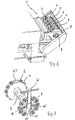
- Fig. 1 shows a schematic representation of a laser cutting machine L for automatically changing cutting nozzles with a change-in-position nozzle changing magazine 1 first variant and with a cutting head 2, which has a cutting nozzle S exchangeably connected to the cutting head.
- the nozzle change magazine 1 first variant is designed to be linearly movable or can be moved by a linear movement in its X direction. If such a movement of the nozzle changing magazine 1 is caused, due to this movement, a protective cover D arranged in the front region of the nozzle changing magazine 1 can be slid in order to access the magazine wheels 4, 5, 6, 7, 8, which together form a magazine depot. to enable.
- the nozzle change magazine 1 can thus be moved substantially linearly from a rest position to a working position (change position).
- the operation of the protective cover D may be coupled to the movement of the nozzle changing magazine 1 or carried out separately.
- the cutting head 2 is movable in at least two degrees of freedom (XY plane) and was moved by means of a movement unit to the cutting nozzle change position for the purpose of a cutting nozzle change.
- the laser cutting machine L described here is designed so that as many movements as possible can be carried out with the laser cutting machine L itself (X / Y / Z).
- the functional scheme described here is therefore limited during the nozzle change phase essentially to a rotational movement of the nozzle change magazine 1 or the magazine wheels 4, 5, 6, 7, 8.
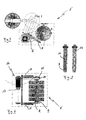
- Fig. 2 shows the nozzle changing magazine 1 acc. Fig. 1 in an enlarged view.
- the nozzle change magazine 1 has a frame structure R, in which the drive and / or carrier shaft 9 for the individual magazine wheels 4, 5, 6, 7, 8 is mounted.
- Each magazine wheel 4, 5, 6, 7, 8 is provided with a plurality of retaining holes, in which the individual cutting nozzles S in the circumferential direction of the magazine wheels 4, 5, 6, 7, 8 are arranged.
- the cutting nozzles S (the designation S applies to all visible cutting nozzles) are secured with an O-ring (not shown) against falling out of the retaining holes.
- Fig. 3 shows the partial sectional view of a arranged on the drive and / or carrier shaft 9 Magazinerads 8 with tool wrench W arranged therein.
- a rear magazine wheel 4 is completely shown and shows a plurality of cutting nozzles S, which are arranged in the circumferential direction on the magazine wheel 4.
- the magazine wheels 4, 5, 6, 7, 8 (magazine wheels 5, 6, 7 not shown here) are in the embodiment shown here, as shown in the sectional view of the magazine wheel 8, provided with two ball detent bolts 10, 10 '.
- the magazine wheel 8 and the drive and / or carrier shaft 9 each have mutually corresponding Aufsteckfräsungen (guide surfaces) 11 and 12, wherein the ball detent bolts 10, 10 'of the magazine wheel 8 when attaching the magazine wheel 8 on the Aufsteckfräsung 11 of the drive and / or carrier shaft 9 engage.
- the magazine wheel 8 can be levered out of the detent points P with the aid of the tool key W (insertion of the tool key W up to the drive and / or carrier shaft 9, then turning the tool key W, magazine wheel 8 is lifted out of detent).
- disposal opening ET (the name ET applies to all visible disposal openings), on the one hand as a disposal opening for removed to be disposed of cutting nozzles and on the other hand serves as an insertion opening for the tool key W.
- Fig. 4 shows a schematically illustrated rotational movement of a nozzle changing magazine 1 'second variant, which rotational movement is used to bring the respective magazine wheels in an exchange / removal position.
- the nozzle changing magazine 1 ' as shown, perform a pivoting movement.
- the frame structure R can be moved from the normal position (POS.II) to an exchange / removal position (POS.I) with the aid of a pneumatic cylinder P in order to ensure optimum access to the removal of a magazine wheel.
- Fig. 5 shows the drive and / or carrier shaft 9 in each of a top and side view.
- Good to recognize the Aufsteckfräsungen (guide surfaces) 11 (the designation 11 applies to all visible Aufsteckfräsungen), each magazine wheel is assigned a Aufsteckfräsung 11.
- the through-bore 13 (the designation 13 applies to all visible through-holes) can also be seen well.
- the through hole 13 corresponds in diameter substantially to the diameter of the disposal opening ET in the magazine wheel, wherein the through hole 13 is aligned with the disposal opening ET in the magazine wheel. This aligned arrangement is achieved by means of Aufsteckfräsmaschine 11, which ensure that the magazine wheel is in a defined position on the drive and / or carrier shaft 9.
- Fig. 6 shows the top view of the nozzle changing magazine 1 'according to the second variant Fig. 4 with the magazine wheels 4, 5, 6, 7, 8.
- the drive and / or carrier shaft 9 is mounted by means of bearings in the frame structure R.
- the frame structure R itself is pivotally mounted on a kind of base plate (not shown).
- the frame structure R can be pivoted via pneumatic cylinder P.
- the drive / rotation of the magazine wheels 4, 5, 6, 7, 8, can be ensured for example via a toothed belt drive 14.
- a pulley 15 is mounted on the drive and / or carrier shaft 9 and connected to a drive pulley 16 of a motor 17 via the toothed belt 14.
- the rotational movement can be controlled by means of a rotary encoder system on the motor, whereby a precise angular positioning of the magazine wheels 4, 5, 6, 7, 8 can be ensured.
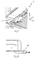
- Fig. 7 shows a section of a laser cutting machine L arranged therein nozzle change magazine 1.
- the protective cover D is closed (rest position) and the nozzle changing magazine thus protected in cutting operation against the ingress of cutting dust or the like.
- the nozzle changing magazine 1 can exert a linear movement, whereby the protective cover D is pushed.
- the nozzle change magazine thus moves into its change position (working position).
- Fig. 8 shows the schematic representation of a provided on a nozzle changing magazine 1 collecting element 18.
- the collecting element 18 is designed here as a drawer and allows an operator in the extended state, the removal of ejected or disposed cutting nozzles.
- Fig. 9 shows the step-by-step flow chart ( AH ) for automatically changing cutting nozzles S in a laser cutting machine.
- the drive and / or carrier shaft 9 with the attached Magazinerad 4 is always positioned in a standby position (rest position) of the nozzle changing magazine so that the central disposal opening ET of the magazine wheel 4 and the through holes 13 of the drive and / or carrier shaft 9 vertically stand.
- the nozzle change magazine is always in stripping position (change position) acc.
- Position A the step-by-step flow chart
- a movement unit moves the cutting head 2 into a predetermined X / Y position (change position) to the corresponding magazine wheel 4.
- an adjustment of the cutting head 2 takes place only in the Z direction (vertical orientation)
- the cutting head 2, the cutting nozzle S in the Z-axis in the corresponding disposal opening ET moves.
- the outer spring housing a arranged on the cutting head 2 quick coupling 3 moves to the shoulder of the magazine wheel 4 and the further descent in the Z direction, for example, set a "disconnect value", compresses the quick coupling 3 gem.
- Position C The locking mechanism of the quick coupling 3 is unlocked and the cutting nozzle S is blown out of the unlocked nozzle by a cutting gas pulse.
- the disposal opening ET in the magazine wheel 4 or the through-bore 13 in the drive and / or carrier shaft 9 the cutting nozzle S to be disposed of arrives in the collecting element 18 arranged below the magazine wheel 4.
- a device for detecting cutting nozzles can be provided, with which it can be checked whether a cutting nozzle S is present in the new magazine position.
- the device for detecting the cutting nozzles can be designed, for example, as an optical light barrier, inductive or capacitive proximity switch or as a magnetically or electrically operating detector system, to name only a small selection. If no cutting nozzle is detected, the magazine wheel 4 is rotated to the next position until a cutting nozzle is detected. Subsequently, the cutting head 2 immersed gem.
- Position E back to a stored "Connect value” and coupled gem.
- Position F the new cutting nozzle. Thereafter, the cutting head 2 acc. Position G in Z direction and cutting operation can be continued.
- the nozzle change magazine or the magazine wheel 4 consequently rotates again into the starting position.
- Position H (essentially corresponds to position A ), so that the nozzle change process can be restarted if necessary.
Landscapes
- Physics & Mathematics (AREA)
- Optics & Photonics (AREA)
- Engineering & Computer Science (AREA)
- Plasma & Fusion (AREA)
- Mechanical Engineering (AREA)
- Laser Beam Processing (AREA)
- Automatic Tool Replacement In Machine Tools (AREA)
- Perforating, Stamping-Out Or Severing By Means Other Than Cutting (AREA)
Priority Applications (7)
| Application Number | Priority Date | Filing Date | Title |
|---|---|---|---|
| EP08405102A EP2108475B1 (fr) | 2008-04-09 | 2008-04-09 | Dispositif et procédé destinés au changement automatique d'ajutage de coupe |
| AT08405102T ATE468196T1 (de) | 2008-04-09 | 2008-04-09 | Vorrichtung und verfahren zum automatischen wechseln von schneiddüsen |
| DE502008000686T DE502008000686D1 (de) | 2008-04-09 | 2008-04-09 | Vorrichtung und Verfahren zum automatischen Wechseln von Schneiddüsen |
| EP09157102A EP2110198B1 (fr) | 2008-04-09 | 2009-04-01 | Machine de coupage par faisceau avec une tête de travail et un couplage arrangé sur celle-ci pour une buse |
| PT09157102T PT2110198E (pt) | 2008-04-09 | 2009-04-01 | Acoplamento de bocal para máquina de usinagem a laser |
| AT09157102T ATE520496T1 (de) | 2008-04-09 | 2009-04-01 | Schneidstrahlmaschine mit einem bearbeitungskopf und einer auf diesem angeordneten kupplung für eine düse |
| CN200910134412.3A CN101554701B (zh) | 2008-04-09 | 2009-04-09 | 用于自动更换切割喷嘴的装置和方法 |
Applications Claiming Priority (1)
| Application Number | Priority Date | Filing Date | Title |
|---|---|---|---|
| EP08405102A EP2108475B1 (fr) | 2008-04-09 | 2008-04-09 | Dispositif et procédé destinés au changement automatique d'ajutage de coupe |
Publications (2)
| Publication Number | Publication Date |
|---|---|
| EP2108475A1 true EP2108475A1 (fr) | 2009-10-14 |
| EP2108475B1 EP2108475B1 (fr) | 2010-05-19 |
Family
ID=39712488
Family Applications (2)
| Application Number | Title | Priority Date | Filing Date |
|---|---|---|---|
| EP08405102A Active EP2108475B1 (fr) | 2008-04-09 | 2008-04-09 | Dispositif et procédé destinés au changement automatique d'ajutage de coupe |
| EP09157102A Active EP2110198B1 (fr) | 2008-04-09 | 2009-04-01 | Machine de coupage par faisceau avec une tête de travail et un couplage arrangé sur celle-ci pour une buse |
Family Applications After (1)
| Application Number | Title | Priority Date | Filing Date |
|---|---|---|---|
| EP09157102A Active EP2110198B1 (fr) | 2008-04-09 | 2009-04-01 | Machine de coupage par faisceau avec une tête de travail et un couplage arrangé sur celle-ci pour une buse |
Country Status (5)
| Country | Link |
|---|---|
| EP (2) | EP2108475B1 (fr) |
| CN (1) | CN101554701B (fr) |
| AT (2) | ATE468196T1 (fr) |
| DE (1) | DE502008000686D1 (fr) |
| PT (1) | PT2110198E (fr) |
Cited By (6)
| Publication number | Priority date | Publication date | Assignee | Title |
|---|---|---|---|---|
| CN103143846A (zh) * | 2013-03-20 | 2013-06-12 | 江苏扬力数控机床有限公司 | 一种激光切割机转塔式喷嘴自动更换装置 |
| WO2014195022A3 (fr) * | 2013-06-07 | 2015-02-26 | Trumpf Werkzeugmaschinen Gmbh + Co. Kg | Tête d'usinage pour machine d'usinage par laser ainsi que machine d'usinage par laser et procédé de remplacement d'un verre de protection dans la tête d'usinage |
| EP2801442B1 (fr) | 2013-05-06 | 2015-09-16 | Biesse S.p.A. | Tête à jet d'eau pour le coupage d'un matériau par jet d'eau hydro-abrasif à haute pression |
| EP3345725A1 (fr) * | 2017-01-06 | 2018-07-11 | Gottfried Wilhelm Leibniz Universität Hannover | Dispositif de coupe par jet de liquide |
| CN109807602A (zh) * | 2019-02-13 | 2019-05-28 | 苏州领智迅创智能装备有限公司 | 切割嘴自动更换装置的使用方法 |
| CN113641149A (zh) * | 2021-10-18 | 2021-11-12 | 思特博恩(常州)新材料科技有限公司 | 刀库运行控制方法、装置、设备及存储介质 |
Families Citing this family (13)
| Publication number | Priority date | Publication date | Assignee | Title |
|---|---|---|---|---|
| CN104692117A (zh) * | 2015-01-13 | 2015-06-10 | 无锡万洪电子机械有限公司 | 一种多工位间隙转动真空吸持机构 |
| CN106552989B (zh) * | 2017-01-12 | 2019-08-23 | 上海电气核电设备有限公司 | 机器人焊接系统的气体保护焊钨极自动更换装置及方法 |
| CN108015438B (zh) * | 2018-01-18 | 2023-10-03 | 济南邦德激光股份有限公司 | 一种激光头调焦方法、装置及激光切割机 |
| DE102018118076A1 (de) * | 2018-07-26 | 2020-01-30 | Bystronic Laser Ag | Laserdüse, Düsenaufnahme, Düsenkupplung und Werkzeugmaschine |
| CN111375911A (zh) * | 2019-06-06 | 2020-07-07 | 济南邦德激光股份有限公司 | 一种自动切割板材方法 |
| WO2020264122A1 (fr) | 2019-06-25 | 2020-12-30 | Hypertherm, Inc. | Mécanismes de verrouillage dans un système de traitement de matériau |
| CN111169979B (zh) * | 2019-12-10 | 2021-06-15 | 苏州市创怡盛实业有限公司 | 机械手搬运方法以及系统 |
| CN111618431B (zh) * | 2020-06-08 | 2022-04-29 | 松山湖材料实验室 | 激光设备气嘴的控制方法及系统 |
| CN111843448B (zh) * | 2020-07-31 | 2022-02-18 | 东科克诺尔商用车制动技术有限公司 | 一种用于容积式压缩机流量测量的喷嘴自动更换装置 |
| AT523733B1 (de) * | 2020-10-14 | 2021-11-15 | Ess Holding Gmbh | Vorrichtung zum Wechseln von Bearbeitungsmedien |
| CN113814539B (zh) * | 2021-10-20 | 2023-10-27 | 江苏扬光机械制造有限公司 | 一种自保养的焊接枪检测上料系统 |
| CN114799585B (zh) * | 2022-06-14 | 2024-02-02 | 广东宏石激光技术股份有限公司 | 一种激光切割机用自动清洗检测更换喷嘴的装置 |
| CN118162821B (zh) * | 2024-05-15 | 2024-08-09 | 上海众冠智能设备有限公司 | 一种柔性化生产线用机器人焊接工作站 |
Citations (6)
| Publication number | Priority date | Publication date | Assignee | Title |
|---|---|---|---|---|
| EP0312861A1 (fr) * | 1987-10-21 | 1989-04-26 | Messer Griesheim Gmbh | Procédé et dispositif pour changer automatiquement des buses de brûleurs |
| DE10056330C1 (de) * | 1999-09-16 | 2002-03-07 | Precitec Kg | Wechselvorrichtung für einen Linsenhalter eines Anschlußkopfs zur Bearbeitung eines Werkstücks mittels eines Laserstrahls |
| EP1602438A2 (fr) | 2004-05-26 | 2005-12-07 | Yamazaki Mazak Corporation | Magasin de changement d'outil pour une machine à faisceau laser |
| JP2006263765A (ja) | 2005-03-23 | 2006-10-05 | Amada Co Ltd | レーザ加工機のノズル自動交換装置 |
| EP1894665A2 (fr) * | 2006-08-29 | 2008-03-05 | Yamazaki Mazak Corporation | Changeur automatique d'outils dans une machine à faisceau laser |
| EP1894664A2 (fr) * | 2006-08-29 | 2008-03-05 | Yamazaki Mazak Corporation | Changeur automatique d'outils dans une machine à faisceau laser |
Family Cites Families (6)
| Publication number | Priority date | Publication date | Assignee | Title |
|---|---|---|---|---|
| JPH11221691A (ja) | 1998-02-04 | 1999-08-17 | Matsushita Electric Ind Co Ltd | レーザ加工装置 |
| DE20114990U1 (de) | 2001-09-11 | 2003-01-23 | Precitec KG, 76571 Gaggenau | Laserbearbeitungskopf |
| JP2005334921A (ja) | 2004-05-26 | 2005-12-08 | Yamazaki Mazak Corp | レーザ加工機におけるノズルチェンジマガジン |
| DE102005049283A1 (de) * | 2005-10-14 | 2007-04-19 | Branson Ultraschall Niederlassung Der Emerson Technologies Gmbh & Co. Ohg | Schnellwechseleinrichtung für das schwingende Werkzeug einer Vibrationsschweißmaschine |
| JP4723456B2 (ja) | 2006-10-27 | 2011-07-13 | 三菱電機株式会社 | 加工ヘッドおよびノズル交換装置およびレーザ加工装置 |
| DE102007024366A1 (de) * | 2007-05-23 | 2008-11-27 | Trumpf Werkzeugmaschinen Gmbh + Co. Kg | Einrichtung zum Wechseln einer Laserbearbeitungsdüse an einem Laserbearbeitungskopf |
-
2008
- 2008-04-09 AT AT08405102T patent/ATE468196T1/de active
- 2008-04-09 EP EP08405102A patent/EP2108475B1/fr active Active
- 2008-04-09 DE DE502008000686T patent/DE502008000686D1/de active Active
-
2009
- 2009-04-01 PT PT09157102T patent/PT2110198E/pt unknown
- 2009-04-01 EP EP09157102A patent/EP2110198B1/fr active Active
- 2009-04-01 AT AT09157102T patent/ATE520496T1/de active
- 2009-04-09 CN CN200910134412.3A patent/CN101554701B/zh active Active
Patent Citations (6)
| Publication number | Priority date | Publication date | Assignee | Title |
|---|---|---|---|---|
| EP0312861A1 (fr) * | 1987-10-21 | 1989-04-26 | Messer Griesheim Gmbh | Procédé et dispositif pour changer automatiquement des buses de brûleurs |
| DE10056330C1 (de) * | 1999-09-16 | 2002-03-07 | Precitec Kg | Wechselvorrichtung für einen Linsenhalter eines Anschlußkopfs zur Bearbeitung eines Werkstücks mittels eines Laserstrahls |
| EP1602438A2 (fr) | 2004-05-26 | 2005-12-07 | Yamazaki Mazak Corporation | Magasin de changement d'outil pour une machine à faisceau laser |
| JP2006263765A (ja) | 2005-03-23 | 2006-10-05 | Amada Co Ltd | レーザ加工機のノズル自動交換装置 |
| EP1894665A2 (fr) * | 2006-08-29 | 2008-03-05 | Yamazaki Mazak Corporation | Changeur automatique d'outils dans une machine à faisceau laser |
| EP1894664A2 (fr) * | 2006-08-29 | 2008-03-05 | Yamazaki Mazak Corporation | Changeur automatique d'outils dans une machine à faisceau laser |
Cited By (12)
| Publication number | Priority date | Publication date | Assignee | Title |
|---|---|---|---|---|
| CN103143846A (zh) * | 2013-03-20 | 2013-06-12 | 江苏扬力数控机床有限公司 | 一种激光切割机转塔式喷嘴自动更换装置 |
| CN103143846B (zh) * | 2013-03-20 | 2014-12-03 | 江苏扬力数控机床有限公司 | 一种激光切割机转塔式喷嘴自动更换装置 |
| EP2801442B1 (fr) | 2013-05-06 | 2015-09-16 | Biesse S.p.A. | Tête à jet d'eau pour le coupage d'un matériau par jet d'eau hydro-abrasif à haute pression |
| EP2801442B2 (fr) † | 2013-05-06 | 2018-08-08 | Biesse S.p.A. | Tête à jet d'eau pour le coupage d'un matériau par jet d'eau hydro-abrasif à haute pression |
| US10343259B2 (en) | 2013-05-06 | 2019-07-09 | Biesse S.P.A. | Water-jet operating head for cutting materials with a hydro-abrasive high pressure jet |
| WO2014195022A3 (fr) * | 2013-06-07 | 2015-02-26 | Trumpf Werkzeugmaschinen Gmbh + Co. Kg | Tête d'usinage pour machine d'usinage par laser ainsi que machine d'usinage par laser et procédé de remplacement d'un verre de protection dans la tête d'usinage |
| DE102013105945B4 (de) | 2013-06-07 | 2025-03-06 | TRUMPF Werkzeugmaschinen SE + Co. KG | Bearbeitungskopf für eine Laserbearbeitungsmaschine sowie Laserbearbeitungsmaschine und Verfahren zum Wechsel eines Schutzglases im Bearbeitungskopf |
| EP3345725A1 (fr) * | 2017-01-06 | 2018-07-11 | Gottfried Wilhelm Leibniz Universität Hannover | Dispositif de coupe par jet de liquide |
| DE102017100183A1 (de) * | 2017-01-06 | 2018-07-12 | Gottfried Wilhelm Leibniz Universität Hannover | Fluidstrahlschneidvorrichtung |
| CN109807602A (zh) * | 2019-02-13 | 2019-05-28 | 苏州领智迅创智能装备有限公司 | 切割嘴自动更换装置的使用方法 |
| CN109807602B (zh) * | 2019-02-13 | 2022-04-12 | 苏州领创先进智能装备有限公司 | 切割嘴自动更换装置的使用方法 |
| CN113641149A (zh) * | 2021-10-18 | 2021-11-12 | 思特博恩(常州)新材料科技有限公司 | 刀库运行控制方法、装置、设备及存储介质 |
Also Published As
| Publication number | Publication date |
|---|---|
| EP2110198A2 (fr) | 2009-10-21 |
| CN101554701B (zh) | 2015-11-25 |
| EP2110198A3 (fr) | 2010-09-08 |
| ATE520496T1 (de) | 2011-09-15 |
| ATE468196T1 (de) | 2010-06-15 |
| CN101554701A (zh) | 2009-10-14 |
| EP2108475B1 (fr) | 2010-05-19 |
| DE502008000686D1 (de) | 2010-07-01 |
| EP2110198B1 (fr) | 2011-08-17 |
| PT2110198E (pt) | 2011-10-11 |
Similar Documents
| Publication | Publication Date | Title |
|---|---|---|
| EP2108475B1 (fr) | Dispositif et procédé destinés au changement automatique d'ajutage de coupe | |
| DE102013105945B4 (de) | Bearbeitungskopf für eine Laserbearbeitungsmaschine sowie Laserbearbeitungsmaschine und Verfahren zum Wechsel eines Schutzglases im Bearbeitungskopf | |
| EP3826814B1 (fr) | Scie à panneaux | |
| EP2842689B1 (fr) | Dispositif et procédé de remplacement d'une meule | |
| EP1260307B1 (fr) | Machine-outil et procédé d'usinage d'une pièce en forme de barre | |
| EP3093080B1 (fr) | Dispositif de changement de matrice comprenant une matrice interchangeable et dome de matrice adaptés et procédé destiné au retrait et à l'insertion de la matrice interchangeable | |
| EP2078584B1 (fr) | Dispositif mécanique destiné au montage et/ou au démontage d'une tuyère laser et machine de traitement laser dotée d'un tel dispositif mécanique | |
| AT500768A1 (de) | Bearbeitungseinrichtung | |
| DE102011053862A1 (de) | Vorrichtung zum Anbringen einer Schnittbahn an einer Umverpackung sowie ein Verfahren zum Betreiben einer solchen Vorrichtung | |
| DE19944484C1 (de) | Wechselvorrichtung für einen Linsenhalter eines Anschlusskopfs zur Bearbeitung eines Werkstücks mittels eines Laserstrahls | |
| DE3542496A1 (de) | Verfahren und vorrichtung zum zufuehren von montageteilen | |
| DE102009027996B4 (de) | Schneidsystem insbesondere zum Abtrennen eines Angusses von einem Werkstück | |
| WO2009080328A1 (fr) | Procédé de traitement d'un bord latéral d'un panneau, et dispositif pour la mise en oeuvre de ce procédé | |
| DE202009018934U1 (de) | Werkzeugmaschine | |
| EP0976508B1 (fr) | Surface de support de pièces pour un dispositif de coupe | |
| DE2907208A1 (de) | Fraesmaschine | |
| EP2939768B1 (fr) | Embarreur avec magasin | |
| DE10056330C1 (de) | Wechselvorrichtung für einen Linsenhalter eines Anschlußkopfs zur Bearbeitung eines Werkstücks mittels eines Laserstrahls | |
| DE29713627U1 (de) | Festwalzmaschine für Kurbelwellen | |
| DE102012212809A1 (de) | Vorrichtung zur Reinigung von Bauteilen | |
| DE10103582C2 (de) | Einrichtung für selbsttätig ablaufende Kerbschlagbiegeversuche und Verfahren zur Durchführung derselben | |
| DE102018104199B4 (de) | Werkzeugmaschine mit Arbeitsraum, Rüstplatz und Roboterarm und Verfahren zu deren Betrieb | |
| DE68902502T2 (de) | Automatische maschine zum verteilen und setzen von ringen auf verbrennungsmotorkolben. | |
| EP3338940A1 (fr) | Dispositif d'usinage à commande technique de programmation | |
| WO2023186570A2 (fr) | Dispositif d'impression 3d doté d'un dispositif de détection pour vérifier le fonctionnement et dispositif d'entretien pour opérations de nettoyage et/ou de remplacement actionnées par une force extérieure |
Legal Events
| Date | Code | Title | Description |
|---|---|---|---|
| PUAI | Public reference made under article 153(3) epc to a published international application that has entered the european phase |
Free format text: ORIGINAL CODE: 0009012 |
|
| 17P | Request for examination filed |
Effective date: 20090418 |
|
| AK | Designated contracting states |
Kind code of ref document: A1 Designated state(s): AT BE BG CH CY CZ DE DK EE ES FI FR GB GR HR HU IE IS IT LI LT LU LV MC MT NL NO PL PT RO SE SI SK TR |
|
| AX | Request for extension of the european patent |
Extension state: AL BA MK RS |
|
| GRAP | Despatch of communication of intention to grant a patent |
Free format text: ORIGINAL CODE: EPIDOSNIGR1 |
|
| GRAS | Grant fee paid |
Free format text: ORIGINAL CODE: EPIDOSNIGR3 |
|
| GRAA | (expected) grant |
Free format text: ORIGINAL CODE: 0009210 |
|
| AK | Designated contracting states |
Kind code of ref document: B1 Designated state(s): AT BE BG CH CY CZ DE DK EE ES FI FR GB GR HR HU IE IS IT LI LT LU LV MC MT NL NO PL PT RO SE SI SK TR |
|
| REG | Reference to a national code |
Ref country code: GB Ref legal event code: FG4D Free format text: NOT ENGLISH |
|
| REG | Reference to a national code |
Ref country code: CH Ref legal event code: EP |
|
| AKX | Designation fees paid |
Designated state(s): AT BE BG CH CY CZ DE DK EE ES FI FR GB GR HR HU IE IS IT LI LT LU LV MC MT NL NO PL PT RO SE SI SK TR |
|
| REG | Reference to a national code |
Ref country code: IE Ref legal event code: FG4D Free format text: LANGUAGE OF EP DOCUMENT: GERMAN |
|
| REF | Corresponds to: |
Ref document number: 502008000686 Country of ref document: DE Date of ref document: 20100701 Kind code of ref document: P |
|
| REG | Reference to a national code |
Ref country code: CH Ref legal event code: NV Representative=s name: R. A. EGLI & CO. PATENTANWAELTE |
|
| REG | Reference to a national code |
Ref country code: NL Ref legal event code: VDEP Effective date: 20100519 |
|
| LTIE | Lt: invalidation of european patent or patent extension |
Effective date: 20100519 |
|
| PG25 | Lapsed in a contracting state [announced via postgrant information from national office to epo] |
Ref country code: NO Free format text: LAPSE BECAUSE OF FAILURE TO SUBMIT A TRANSLATION OF THE DESCRIPTION OR TO PAY THE FEE WITHIN THE PRESCRIBED TIME-LIMIT Effective date: 20100819 Ref country code: SE Free format text: LAPSE BECAUSE OF FAILURE TO SUBMIT A TRANSLATION OF THE DESCRIPTION OR TO PAY THE FEE WITHIN THE PRESCRIBED TIME-LIMIT Effective date: 20100519 Ref country code: LT Free format text: LAPSE BECAUSE OF FAILURE TO SUBMIT A TRANSLATION OF THE DESCRIPTION OR TO PAY THE FEE WITHIN THE PRESCRIBED TIME-LIMIT Effective date: 20100519 Ref country code: ES Free format text: LAPSE BECAUSE OF FAILURE TO SUBMIT A TRANSLATION OF THE DESCRIPTION OR TO PAY THE FEE WITHIN THE PRESCRIBED TIME-LIMIT Effective date: 20100830 |
|
| PG25 | Lapsed in a contracting state [announced via postgrant information from national office to epo] |
Ref country code: SI Free format text: LAPSE BECAUSE OF FAILURE TO SUBMIT A TRANSLATION OF THE DESCRIPTION OR TO PAY THE FEE WITHIN THE PRESCRIBED TIME-LIMIT Effective date: 20100519 Ref country code: LV Free format text: LAPSE BECAUSE OF FAILURE TO SUBMIT A TRANSLATION OF THE DESCRIPTION OR TO PAY THE FEE WITHIN THE PRESCRIBED TIME-LIMIT Effective date: 20100519 Ref country code: IS Free format text: LAPSE BECAUSE OF FAILURE TO SUBMIT A TRANSLATION OF THE DESCRIPTION OR TO PAY THE FEE WITHIN THE PRESCRIBED TIME-LIMIT Effective date: 20100919 Ref country code: HR Free format text: LAPSE BECAUSE OF FAILURE TO SUBMIT A TRANSLATION OF THE DESCRIPTION OR TO PAY THE FEE WITHIN THE PRESCRIBED TIME-LIMIT Effective date: 20100519 Ref country code: FI Free format text: LAPSE BECAUSE OF FAILURE TO SUBMIT A TRANSLATION OF THE DESCRIPTION OR TO PAY THE FEE WITHIN THE PRESCRIBED TIME-LIMIT Effective date: 20100519 |
|
| PG25 | Lapsed in a contracting state [announced via postgrant information from national office to epo] |
Ref country code: PL Free format text: LAPSE BECAUSE OF FAILURE TO SUBMIT A TRANSLATION OF THE DESCRIPTION OR TO PAY THE FEE WITHIN THE PRESCRIBED TIME-LIMIT Effective date: 20100519 Ref country code: CY Free format text: LAPSE BECAUSE OF FAILURE TO SUBMIT A TRANSLATION OF THE DESCRIPTION OR TO PAY THE FEE WITHIN THE PRESCRIBED TIME-LIMIT Effective date: 20100616 |
|
| REG | Reference to a national code |
Ref country code: IE Ref legal event code: FD4D |
|
| PG25 | Lapsed in a contracting state [announced via postgrant information from national office to epo] |
Ref country code: EE Free format text: LAPSE BECAUSE OF FAILURE TO SUBMIT A TRANSLATION OF THE DESCRIPTION OR TO PAY THE FEE WITHIN THE PRESCRIBED TIME-LIMIT Effective date: 20100519 Ref country code: DK Free format text: LAPSE BECAUSE OF FAILURE TO SUBMIT A TRANSLATION OF THE DESCRIPTION OR TO PAY THE FEE WITHIN THE PRESCRIBED TIME-LIMIT Effective date: 20100519 Ref country code: NL Free format text: LAPSE BECAUSE OF FAILURE TO SUBMIT A TRANSLATION OF THE DESCRIPTION OR TO PAY THE FEE WITHIN THE PRESCRIBED TIME-LIMIT Effective date: 20100519 Ref country code: IE Free format text: LAPSE BECAUSE OF FAILURE TO SUBMIT A TRANSLATION OF THE DESCRIPTION OR TO PAY THE FEE WITHIN THE PRESCRIBED TIME-LIMIT Effective date: 20100519 |
|
| PG25 | Lapsed in a contracting state [announced via postgrant information from national office to epo] |
Ref country code: SK Free format text: LAPSE BECAUSE OF FAILURE TO SUBMIT A TRANSLATION OF THE DESCRIPTION OR TO PAY THE FEE WITHIN THE PRESCRIBED TIME-LIMIT Effective date: 20100519 Ref country code: RO Free format text: LAPSE BECAUSE OF FAILURE TO SUBMIT A TRANSLATION OF THE DESCRIPTION OR TO PAY THE FEE WITHIN THE PRESCRIBED TIME-LIMIT Effective date: 20100519 Ref country code: CZ Free format text: LAPSE BECAUSE OF FAILURE TO SUBMIT A TRANSLATION OF THE DESCRIPTION OR TO PAY THE FEE WITHIN THE PRESCRIBED TIME-LIMIT Effective date: 20100519 |
|
| PLBE | No opposition filed within time limit |
Free format text: ORIGINAL CODE: 0009261 |
|
| STAA | Information on the status of an ep patent application or granted ep patent |
Free format text: STATUS: NO OPPOSITION FILED WITHIN TIME LIMIT |
|
| 26N | No opposition filed |
Effective date: 20110222 |
|
| PG25 | Lapsed in a contracting state [announced via postgrant information from national office to epo] |
Ref country code: GR Free format text: LAPSE BECAUSE OF FAILURE TO SUBMIT A TRANSLATION OF THE DESCRIPTION OR TO PAY THE FEE WITHIN THE PRESCRIBED TIME-LIMIT Effective date: 20100820 |
|
| REG | Reference to a national code |
Ref country code: DE Ref legal event code: R097 Ref document number: 502008000686 Country of ref document: DE Effective date: 20110221 |
|
| PG25 | Lapsed in a contracting state [announced via postgrant information from national office to epo] |
Ref country code: MC Free format text: LAPSE BECAUSE OF NON-PAYMENT OF DUE FEES Effective date: 20110430 |
|
| PG25 | Lapsed in a contracting state [announced via postgrant information from national office to epo] |
Ref country code: MT Free format text: LAPSE BECAUSE OF FAILURE TO SUBMIT A TRANSLATION OF THE DESCRIPTION OR TO PAY THE FEE WITHIN THE PRESCRIBED TIME-LIMIT Effective date: 20100519 |
|
| GBPC | Gb: european patent ceased through non-payment of renewal fee |
Effective date: 20120409 |
|
| PG25 | Lapsed in a contracting state [announced via postgrant information from national office to epo] |
Ref country code: GB Free format text: LAPSE BECAUSE OF NON-PAYMENT OF DUE FEES Effective date: 20120409 |
|
| PG25 | Lapsed in a contracting state [announced via postgrant information from national office to epo] |
Ref country code: LU Free format text: LAPSE BECAUSE OF NON-PAYMENT OF DUE FEES Effective date: 20110409 |
|
| PG25 | Lapsed in a contracting state [announced via postgrant information from national office to epo] |
Ref country code: PT Free format text: LAPSE BECAUSE OF NON-PAYMENT OF DUE FEES Effective date: 20100519 |
|
| PG25 | Lapsed in a contracting state [announced via postgrant information from national office to epo] |
Ref country code: BG Free format text: LAPSE BECAUSE OF FAILURE TO SUBMIT A TRANSLATION OF THE DESCRIPTION OR TO PAY THE FEE WITHIN THE PRESCRIBED TIME-LIMIT Effective date: 20100819 |
|
| PG25 | Lapsed in a contracting state [announced via postgrant information from national office to epo] |
Ref country code: HU Free format text: LAPSE BECAUSE OF FAILURE TO SUBMIT A TRANSLATION OF THE DESCRIPTION OR TO PAY THE FEE WITHIN THE PRESCRIBED TIME-LIMIT Effective date: 20100519 |
|
| REG | Reference to a national code |
Ref country code: FR Ref legal event code: PLFP Year of fee payment: 8 |
|
| REG | Reference to a national code |
Ref country code: FR Ref legal event code: PLFP Year of fee payment: 9 |
|
| REG | Reference to a national code |
Ref country code: FR Ref legal event code: PLFP Year of fee payment: 10 |
|
| PGFP | Annual fee paid to national office [announced via postgrant information from national office to epo] |
Ref country code: AT Payment date: 20170420 Year of fee payment: 10 |
|
| REG | Reference to a national code |
Ref country code: FR Ref legal event code: PLFP Year of fee payment: 11 |
|
| REG | Reference to a national code |
Ref country code: AT Ref legal event code: MM01 Ref document number: 468196 Country of ref document: AT Kind code of ref document: T Effective date: 20180409 |
|
| PG25 | Lapsed in a contracting state [announced via postgrant information from national office to epo] |
Ref country code: AT Free format text: LAPSE BECAUSE OF NON-PAYMENT OF DUE FEES Effective date: 20180409 |
|
| PGFP | Annual fee paid to national office [announced via postgrant information from national office to epo] |
Ref country code: TR Payment date: 20220407 Year of fee payment: 15 |
|
| P01 | Opt-out of the competence of the unified patent court (upc) registered |
Effective date: 20230522 |
|
| PGFP | Annual fee paid to national office [announced via postgrant information from national office to epo] |
Ref country code: FR Payment date: 20240321 Year of fee payment: 17 Ref country code: BE Payment date: 20240319 Year of fee payment: 17 |
|
| PGFP | Annual fee paid to national office [announced via postgrant information from national office to epo] |
Ref country code: DE Payment date: 20250305 Year of fee payment: 18 |
|
| PGFP | Annual fee paid to national office [announced via postgrant information from national office to epo] |
Ref country code: CH Payment date: 20250501 Year of fee payment: 18 |
|
| REG | Reference to a national code |
Ref country code: BE Ref legal event code: MM Effective date: 20250430 |
|
| PG25 | Lapsed in a contracting state [announced via postgrant information from national office to epo] |
Ref country code: FR Free format text: LAPSE BECAUSE OF NON-PAYMENT OF DUE FEES Effective date: 20250430 |
|
| PG25 | Lapsed in a contracting state [announced via postgrant information from national office to epo] |
Ref country code: BE Free format text: LAPSE BECAUSE OF NON-PAYMENT OF DUE FEES Effective date: 20250430 |
|
| PGFP | Annual fee paid to national office [announced via postgrant information from national office to epo] |
Ref country code: IT Payment date: 20260320 Year of fee payment: 19 |
|
| REG | Reference to a national code |
Ref country code: CH Ref legal event code: U11 Free format text: ST27 STATUS EVENT CODE: U-0-0-U10-U11 (AS PROVIDED BY THE NATIONAL OFFICE) Effective date: 20260501 |