EP2108487A1 - Werkzeugkasten - Google Patents
Werkzeugkasten Download PDFInfo
- Publication number
- EP2108487A1 EP2108487A1 EP09005125A EP09005125A EP2108487A1 EP 2108487 A1 EP2108487 A1 EP 2108487A1 EP 09005125 A EP09005125 A EP 09005125A EP 09005125 A EP09005125 A EP 09005125A EP 2108487 A1 EP2108487 A1 EP 2108487A1
- Authority
- EP
- European Patent Office
- Prior art keywords
- toolbox
- tool
- main body
- hand
- support portion
- Prior art date
- Legal status (The legal status is an assumption and is not a legal conclusion. Google has not performed a legal analysis and makes no representation as to the accuracy of the status listed.)
- Granted
Links
Images


Classifications
-
- B—PERFORMING OPERATIONS; TRANSPORTING
- B25—HAND TOOLS; PORTABLE POWER-DRIVEN TOOLS; MANIPULATORS
- B25H—WORKSHOP EQUIPMENT, e.g. FOR MARKING-OUT WORK; STORAGE MEANS FOR WORKSHOPS
- B25H3/00—Storage means or arrangements for workshops facilitating access to, or handling of, work tools or instruments
- B25H3/02—Boxes
-
- B—PERFORMING OPERATIONS; TRANSPORTING
- B25—HAND TOOLS; PORTABLE POWER-DRIVEN TOOLS; MANIPULATORS
- B25H—WORKSHOP EQUIPMENT, e.g. FOR MARKING-OUT WORK; STORAGE MEANS FOR WORKSHOPS
- B25H3/00—Storage means or arrangements for workshops facilitating access to, or handling of, work tools or instruments
- B25H3/006—Storage means specially adapted for one specific hand apparatus, e.g. an electric drill
Definitions
- the present invention relates to boxes (toolboxes) for storing hand-held tools, such as an electric driver.
- a toolbox includes a toolbox main body for storing hand-held tools, battery packs to be attached to the electric tools, and battery chargers, and a lid for opening and closing the toolbox main body.
- a carrying handle is formed with the toolbox.
- Japanese Laid-Open Patent Publication No. 2003-236772 Japanese Laid-Open Patent Publication No. 391692 teaches a technique for storing a rechargeable tool and a removable battery pack without causing bumping.
- Japanese Laid-Open Utility Model Publication No. 62-19183 discloses a toolbox for storing an electric circular saw and also teaches a technique for compactly storing a circular saw main body and a removable blade.
- Japanese Laid-Open Utility Model Publication No. 5-39879 teaches a technique for storing tools in various shapes and sizes.
- these conventional toolboxes have been intended for storing tools after completion of work and for not using repeatedly or frequently bringing the tools in and out during the working process.
- the conventional toolboxes have been constructed to store the tools in a horizontal laying manner and thus, when the tools are temporarily stored within the toolboxes during the working process, users have to re-grip the tools to change from a horizontal laying position to a working position. Due to this, the conventional toolboxes have been inconvenient to use.
- One aspect according to the present invention includes a toolbox for storing at least one hand-held tool having a tool main body and a handle portion extending from a side portion of the tool main body.
- the toolbox is constructed to be able to store the hand-held tool in a forward leaning position in which a front end portion of the tool main body and a rear end portion of the handle portion are supported by the toolbox.
- FIG. 1 - FIG. 3 show an overall view of a toolbox 1 according to the embodiment.
- the toolbox 1 has a toolbox main body 2 and a lid 3 for opening and closing the toolbox main body 2. Both the toolbox main body 2 and the lid 3 can be made of aluminum.
- a user may be positioned on the right side of the toolbox 1. In the following description, a side where the user is positioned is described as a front side, and the opposite side is described as a back side or a rear side.
- the toolbox main body 2 has a substantially square box shape having a sufficient depth and an opening on the top.
- the toolbox main body 2 has a front wall portion 2a on the user's side, a left side wall portion 2b on the user's left side, a right side wall portion 2c on the user's right side, a rear wall portion 2d on the back side the front wall portion 2a, and a bottom portion (this portion is hidden by a seat portion 30 in FIG. 2 ).
- the lid 3 is supported via a pair of right and left hinge portions 4 on the upper part of the rear wall portion 2d so that the lid 3 can be open or closed in up and down directions.
- the lid 3 is locked in the closed state with a pair of right and left locks 5 mounted on the front side of the lid 3.
- a handle 6 is formed on the upper part of the front wall portion 2a of the toolbox main body 2. The user grips the handle 6 to carry toolbox 1.
- the seat portion 30 can be made of foamed urethane having an adequate cushioning property and placed inside the toolbox main body 2.
- FIG. 4 - FIG. 6 show the seat portion 30.
- Two electric tools 10 and a battery charger 20 can be positioned on the seat portion 30.
- the toolbox 1 of this embodiment is characterized mainly in the seated position of the two electric tools 10.
- the two storable electric tools 10 can be hand-held electric drivers each having a tool main body 11 in a substantially cylindrical column shape and a handle portion 12 extending laterally from the tool main body 11.
- a tool bit 13 such as a driver bit, is attached to a front end of the tool main body 11.
- a battery pack 14 is attached to a rear end portion of the handle portion 12.
- the user holds the electric tool 10 by griping the handle portion 12 with the side of the front end portion (the side of the tool bit 13) of the tool main body 11 oriented forwardly, and in this state, the user pushes the switch lever 15 for performing a boring operation, etc.
- the user is positioned on the right side of the toolbox 1 (the front side of the toolbox 1) and brings in or out the electric tool 10 from a position obliquely upward as shown with an outlined arrow in FIG. 1 .
- This allows the user to bring the electric tool 10 from the front side of the toolbox 1 into the toolbox main body 2 while keeping the same position as the working position and without changing the gripping position of the electric tool 10 to another position.
- the electric tool 10 can be stored in a standing and forward leaning position.
- the two electric tools 10 can be stored in parallel on right and left sides of the battery charger 20.
- the battery charger 20 can have a rectangle box shape.
- the battery charger 20 is stored at a position between the two electric tools 10 which are stored in the parallel manner on right and left sides of the toolbox main body 2.
- the electric tools 10 are stored in a forward leaning position such that the directions along their lengths (longitudinal directions) of the both electric tools 10 are oriented along the open or close direction of the lid 3.
- each of the front end portion of the tool main body 11 and the rear end portion of the handle portion 12 (i.e., the battery pack 14) of each of the electric tools 10 is supported by the seat portion 30, so that each of the electric tools 10 is stored in a position that the rear portion of the tool main body 11 extends obliquely upward from the seat portion 30 (the forward leaning position).
- the front end portion of the tool main body 11 is supported on the rear side portion of the toolbox main body 2
- the rear end portion of the handle portion 12 is supported on the front side portion, so that each of the electric tools 10 is stored in the forward leaning standing position which is substantially same with the position that is taken when the user grips the electric tool 10 during the working process (a working position).
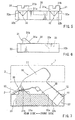
- FIG. 7 shows one of the electric tools 10 being supported on the seat portion 30 in the forward leaning position.
- a pair of front end supporting portions 31 disposed on the right and left sides for supporting the main bodies 11 of the electric tools 10 and a pair of rear end supporting portions 32 disposed on the right and left sides for supporting the rear ends of the handle portions 12 are respectively (i.e. integrally) formed on the upper surface of the seat portion 30.
- the electric tools 10 are respectively supported in a standing position to extend between the front end supporting portions 31 and the rear end supporting portions 32.
- each of the front end supporting portions 31 is formed in a raising manner from the upper surface of the seat portion 30, and has a supporting surface 31 a inclining upwardly towards the rear side and a fitting concave portion 31 b for fitting with the front end portion of the tool main body 11.
- the inclined supporting surfaces 31a is configured to contact the front end portion of the tool main body 11, and the fitting concave portion 31b is configured to accommodate a spindle of the electric tool 10.
- the rear end supporting portions 32 are positioned at the front end portion of the seat portion 30 on the front side of the front end supporting portions 31.
- Each of the rear end supporting portions 32 has a V-shaped supporting recess 32a inclining deeper towards the front side and a fitting concave portion 32b for fitting mainly with the battery pack 14.
- the handle portion 12 is fitted into the handle supporting recess 32a and the battery pack 14 is placed inside the fitting concave portion 32b.
- each of the front end portions (spindles) of the tool main bodies 11 is fitted into corresponding one of the fitting concaves 31b of the front end supporting portions 31 of the toolbox main body 11, and each of the rear end portions of the handle portions 12 (the battery packs 14) is fitted into corresponding one of the handle supporting recesses 32a. Accordingly, each of the electric tools 11 is supported in the forward leaning position without falling off asides.
- Cutting tool relieving concaves 33 are formed at the rear end part of the seat portion 30 (left end portion in FIG. 7 ) on the front end supporting portions 31 for mainly receiving the front ends of the tool bits 13 of the stored electric tools 10.
- each of the supporting holes 34 is formed to be shallow and to have a comparatively larger diameter in order to be compatible with battery chargers in various sizes.
- the electric tools 10 each having the handle portion 12 extending laterally from the tool main body 11 can be stored in a forward leaning position that is slightly leaned forwardly compared to a usual working position.
- a forward leaning position each of the rear portion of the tool main bodies 11 (the end portions toward the side of the user) is kept at a higher position than the tool bit 13.
- each of the base portions of the handles 12 is kept at a higher position than the battery pack 14.
- each of the handle portions 12 is positioned on the side of the user and in the forward leaning position. Due to this, each of the handle portions12 is easily gripped. Accordingly, the user can smoothly and easily bring the electric tools 10 into and out of the toolbox main body 2.
- the known electric tool in this kind has been stored in a horizontally lying position that is, for instance, the same with the position that the electric tool is laid on a flat working table. Because the electric tool has been fitted into a seat portion in the lying position, it has been troublesome to bring the electric tool out by gripping the handle.
- the electric tools 10 can be stored in a forward leaning position while their handle portions 12 are positioned to be opposed to the user. Therefore, the user can store the electric tools 10 in substantially the same position as the working position.
- the electric tool(s) 10 is needed, the user can quickly and easily grip the handle portion 12, withdraw it at an oblique upward direction, and start the working operation in the same position without need of re-gripping the electric tool 10.
- the user can store the electric hand tool 10 by gripping the same maintaining the usual working position, the user can also utilize the toolbox 1 as a tool keeper for temporarily storing the electric tool(s) 10 during a machining operation, such as a boring operation.
- the user who may be positioned on the front side of the toolbox 1 can store the electric tool(s) 10 by moving it in an obliquely downward direction and can bring out the electric tool(s) by moving it in an opposite direction. Therefore, the user can store or bring out the electric tool(s) 10 while he or she takes a comfortable posture without need of further bending and stretching his or her arms.
- the two electric tools 10 are stored in parallel on right and left sides of the battery charger 20 for the battery pack 14 of the electric tools 10 and are spaced from each other by a suitable distance. Due to this, the electric tools 10 and the battery charger 20 do not interfere with each other when they are brought in or out from the toolbox 1. In addition, the user gripping one of the electric tools 10 can quickly and easily bring in and out one of the electric tools 10 because the hand of the user may not contact the other electric tool 10.
- the electric tools 10 are not stored in a simply upright position on the upper surface of the seat portion 30 but in the forward leaning position inclining the front end portion of the tool main body 11 downward. Therefore, the electric tools 10 can be stored to have a height smaller than the height in the upright position.
- electric drivers are exemplified as tools to be stored in the toolbox described in the above embodiment.
- Electric screwdrivers and other electric tools can also be stored in the toolbox.
- the toolbox can store electric tools that receive the supply of power from an AC power source, other than the electric tools having battery packs.
- the toolbox can also be used for storing pneumatic tools other than electric tools.
- the seat portion 30 in the embodiment has an adequate cushion property
- the seat portion may be made of metal, hard resin or wood. It is explicitly stated that all features disclosed in the description and/or the claims are intended to be disclosed separately and independently from each other for the purpose of original disclosure as well as for the purpose of restricting the claimed invention independent of the composition of the features in the embodiments and/or the claims. It is explicitly stated that all value ranges or indications of groups of entities disclose every possible intermediate value or intermediate entity for the purpose of original disclosure as well as for the purpose of restricting the claimed invention, in particular as limits of value ranges.
Landscapes
- Engineering & Computer Science (AREA)
- Mechanical Engineering (AREA)
- Workshop Equipment, Work Benches, Supports, Or Storage Means (AREA)
- Packaging Of Annular Or Rod-Shaped Articles, Wearing Apparel, Cassettes, Or The Like (AREA)
Applications Claiming Priority (1)
| Application Number | Priority Date | Filing Date | Title |
|---|---|---|---|
| JP2008100311A JP2009248262A (ja) | 2008-04-08 | 2008-04-08 | 工具収納箱 |
Publications (2)
| Publication Number | Publication Date |
|---|---|
| EP2108487A1 true EP2108487A1 (de) | 2009-10-14 |
| EP2108487B1 EP2108487B1 (de) | 2012-12-19 |
Family
ID=40933683
Family Applications (1)
| Application Number | Title | Priority Date | Filing Date |
|---|---|---|---|
| EP09005125A Active EP2108487B1 (de) | 2008-04-08 | 2009-04-07 | Werkzeugkasten |
Country Status (4)
| Country | Link |
|---|---|
| US (1) | US8439192B2 (de) |
| EP (1) | EP2108487B1 (de) |
| JP (1) | JP2009248262A (de) |
| CN (1) | CN101554723B (de) |
Families Citing this family (13)
| Publication number | Priority date | Publication date | Assignee | Title |
|---|---|---|---|---|
| EP2181775B1 (de) * | 2008-11-04 | 2012-09-12 | Siemens Aktiengesellschaft | Halterung für grosse Bauteile mit verbesserten Spritzschutz |
| JP2011230255A (ja) | 2010-04-28 | 2011-11-17 | Makita Corp | 工具収容バッグ及び工具収容バッグセット |
| US9341403B2 (en) | 2012-07-11 | 2016-05-17 | Milwaukee Electric Tool Corporation | Cooler |
| US9539722B2 (en) | 2012-12-19 | 2017-01-10 | Milwaukee Electric Tool Corporation | Tool storage devices |
| CN205968920U (zh) | 2014-07-22 | 2017-02-22 | 米沃奇电动工具公司 | 工具储存装置 |
| DE102014226234A1 (de) * | 2014-12-17 | 2016-06-23 | Robert Bosch Gmbh | Handwerkzeugkoffer |
| USD834817S1 (en) | 2015-07-17 | 2018-12-04 | Milwaukee Electric Tool Corporation | Bag |
| USD810435S1 (en) | 2015-07-17 | 2018-02-20 | Milwaukee Electric Tool Corporation | Bag |
| USD844324S1 (en) | 2015-07-17 | 2019-04-02 | Milwaukee Electric Tool Corporation | Bag |
| US9872547B2 (en) | 2015-11-25 | 2018-01-23 | Milwaukee Electric Tool Corporation | Handle assembly for a case |
| DE102015121891A1 (de) * | 2015-12-15 | 2017-06-22 | Wagner Spraytech (UK) Ltd. | System umfassend ein Heißlufthandgerät und einen Transportkoffer für das Heißlufthandgerät, Transportkoffer sowie Verfahren zum Betrieb eines Heißlufthandgeräts |
| US10801263B2 (en) * | 2018-02-23 | 2020-10-13 | Werner Co. | Ladder with top for holding an impact driver and method |
| DE102022210256A1 (de) * | 2022-09-28 | 2024-03-28 | Robert Bosch Gesellschaft mit beschränkter Haftung | Werkzeugkoffer für eine Handwerkzeugmaschine |
Citations (9)
| Publication number | Priority date | Publication date | Assignee | Title |
|---|---|---|---|---|
| JPS6219183U (de) | 1985-07-19 | 1987-02-04 | ||
| JPH0539879U (ja) | 1991-11-06 | 1993-05-28 | 日立工機株式会社 | 製品収納ケース |
| US20020104709A1 (en) * | 2001-02-05 | 2002-08-08 | Hines Kenneth Joshua | Tool box mountable on the top step of a foldable ladder |
| EP1285732A1 (de) * | 2001-08-21 | 2003-02-26 | TTS Tooltechnic Systems AG & Co. KG | Werkzeugkoffer |
| JP2003236772A (ja) | 2002-02-18 | 2003-08-26 | Makita Corp | 電動工具の収納ケース |
| DE102004060294A1 (de) * | 2004-12-15 | 2006-06-22 | Robert Bosch Gmbh | Vorrichtung mit einem Handwerkzeugmaschinenkoffer |
| US20060260964A1 (en) * | 2005-05-17 | 2006-11-23 | Feldmann William M | Case and organizer tray for a power tool |
| WO2007071128A1 (fr) * | 2005-12-22 | 2007-06-28 | Top Link Industrial Co., Ltd | Support pour outil electrique |
| DE102006000939A1 (de) * | 2006-01-05 | 2007-07-12 | Mobiletron Electronics Co., Ltd. | Werkzeugkasten zur Aufbewahrung eines elektrischen Handwerkzeugs und dessen Zubehörs |
Family Cites Families (4)
| Publication number | Priority date | Publication date | Assignee | Title |
|---|---|---|---|---|
| JPS6219183A (ja) | 1985-07-19 | 1987-01-27 | 株式会社 ソ−ケン | レ−ザ−光照射治療装置 |
| JPH0539879A (ja) | 1991-08-05 | 1993-02-19 | Sekisui Chem Co Ltd | 空圧作動式バルブ |
| US6571949B2 (en) * | 2000-06-05 | 2003-06-03 | Motorola, Inc. | Power toolbox |
| DE102004040922A1 (de) * | 2004-08-24 | 2006-03-02 | Robert Bosch Gmbh | Wechselhandwerkzeugakkueinheit, Handwerkzeugmaschine und Ladevorrichtung |
-
2008
- 2008-04-08 JP JP2008100311A patent/JP2009248262A/ja active Pending
-
2009
- 2009-02-17 CN CN2009100073603A patent/CN101554723B/zh active Active
- 2009-04-06 US US12/385,360 patent/US8439192B2/en active Active
- 2009-04-07 EP EP09005125A patent/EP2108487B1/de active Active
Patent Citations (10)
| Publication number | Priority date | Publication date | Assignee | Title |
|---|---|---|---|---|
| JPS6219183U (de) | 1985-07-19 | 1987-02-04 | ||
| JPH0539879U (ja) | 1991-11-06 | 1993-05-28 | 日立工機株式会社 | 製品収納ケース |
| US20020104709A1 (en) * | 2001-02-05 | 2002-08-08 | Hines Kenneth Joshua | Tool box mountable on the top step of a foldable ladder |
| EP1285732A1 (de) * | 2001-08-21 | 2003-02-26 | TTS Tooltechnic Systems AG & Co. KG | Werkzeugkoffer |
| JP2003236772A (ja) | 2002-02-18 | 2003-08-26 | Makita Corp | 電動工具の収納ケース |
| JP3916962B2 (ja) | 2002-02-18 | 2007-05-23 | 株式会社マキタ | 電動工具の収納ケース |
| DE102004060294A1 (de) * | 2004-12-15 | 2006-06-22 | Robert Bosch Gmbh | Vorrichtung mit einem Handwerkzeugmaschinenkoffer |
| US20060260964A1 (en) * | 2005-05-17 | 2006-11-23 | Feldmann William M | Case and organizer tray for a power tool |
| WO2007071128A1 (fr) * | 2005-12-22 | 2007-06-28 | Top Link Industrial Co., Ltd | Support pour outil electrique |
| DE102006000939A1 (de) * | 2006-01-05 | 2007-07-12 | Mobiletron Electronics Co., Ltd. | Werkzeugkasten zur Aufbewahrung eines elektrischen Handwerkzeugs und dessen Zubehörs |
Also Published As
| Publication number | Publication date |
|---|---|
| US8439192B2 (en) | 2013-05-14 |
| CN101554723B (zh) | 2013-03-13 |
| CN101554723A (zh) | 2009-10-14 |
| JP2009248262A (ja) | 2009-10-29 |
| EP2108487B1 (de) | 2012-12-19 |
| US20090250365A1 (en) | 2009-10-08 |
Similar Documents
| Publication | Publication Date | Title |
|---|---|---|
| EP2108487B1 (de) | Werkzeugkasten | |
| CN101522376B (zh) | 安装电动工具以提供工作站的工具箱设备 | |
| US20110073335A1 (en) | Power tools | |
| US8415046B2 (en) | Electric tools | |
| US5224531A (en) | Portable shop/toolbox | |
| US20100230313A1 (en) | Portable tool case and workstation | |
| US5351730A (en) | Multipurpose portable workbench | |
| JP6500121B2 (ja) | 手動工具トランク、システム、および、位置決めする方法 | |
| JP6300271B2 (ja) | チェーンソー | |
| US7971716B2 (en) | Adjustable inclined tool box | |
| TW201217115A (en) | capable of reducing the external dimension of the tool box while enhancing the receiving capability | |
| US20250144783A1 (en) | Modular work station | |
| US20240217084A1 (en) | Rotary tool | |
| US20090045088A1 (en) | Electric tool holder with accessory pod | |
| EP1384542A1 (de) | Gleitbare Gehrungssäge | |
| JP2012196734A (ja) | 電動工具 | |
| US6206063B1 (en) | Multifunctional work box | |
| US7434819B1 (en) | Portable work area | |
| US6910577B2 (en) | Ergonomic tool box | |
| CN209919859U (zh) | 一种手提工具箱用可收纳式的把手装置 | |
| GB2500476A (en) | Tool storage box with auxiliary case on front | |
| JPH047906Y2 (de) | ||
| GB2420309A (en) | Portable storage container and workbench | |
| JPH0735003U (ja) | 木材等の回転加工機 | |
| EP0214807A2 (de) | Lagerung von Werkzeugen |
Legal Events
| Date | Code | Title | Description |
|---|---|---|---|
| PUAI | Public reference made under article 153(3) epc to a published international application that has entered the european phase |
Free format text: ORIGINAL CODE: 0009012 |
|
| AK | Designated contracting states |
Kind code of ref document: A1 Designated state(s): AT BE BG CH CY CZ DE DK EE ES FI FR GB GR HR HU IE IS IT LI LT LU LV MC MK MT NL NO PL PT RO SE SI SK TR |
|
| 17P | Request for examination filed |
Effective date: 20100413 |
|
| GRAP | Despatch of communication of intention to grant a patent |
Free format text: ORIGINAL CODE: EPIDOSNIGR1 |
|
| GRAS | Grant fee paid |
Free format text: ORIGINAL CODE: EPIDOSNIGR3 |
|
| GRAA | (expected) grant |
Free format text: ORIGINAL CODE: 0009210 |
|
| AK | Designated contracting states |
Kind code of ref document: B1 Designated state(s): AT BE BG CH CY CZ DE DK EE ES FI FR GB GR HR HU IE IS IT LI LT LU LV MC MK MT NL NO PL PT RO SE SI SK TR |
|
| REG | Reference to a national code |
Ref country code: GB Ref legal event code: FG4D |
|
| REG | Reference to a national code |
Ref country code: CH Ref legal event code: EP |
|
| REG | Reference to a national code |
Ref country code: AT Ref legal event code: REF Ref document number: 589124 Country of ref document: AT Kind code of ref document: T Effective date: 20130115 |
|
| REG | Reference to a national code |
Ref country code: DE Ref legal event code: R096 Ref document number: 602009011974 Country of ref document: DE Effective date: 20130214 |
|
| PG25 | Lapsed in a contracting state [announced via postgrant information from national office to epo] |
Ref country code: LT Free format text: LAPSE BECAUSE OF FAILURE TO SUBMIT A TRANSLATION OF THE DESCRIPTION OR TO PAY THE FEE WITHIN THE PRESCRIBED TIME-LIMIT Effective date: 20121219 Ref country code: SE Free format text: LAPSE BECAUSE OF FAILURE TO SUBMIT A TRANSLATION OF THE DESCRIPTION OR TO PAY THE FEE WITHIN THE PRESCRIBED TIME-LIMIT Effective date: 20121219 Ref country code: FI Free format text: LAPSE BECAUSE OF FAILURE TO SUBMIT A TRANSLATION OF THE DESCRIPTION OR TO PAY THE FEE WITHIN THE PRESCRIBED TIME-LIMIT Effective date: 20121219 Ref country code: ES Free format text: LAPSE BECAUSE OF FAILURE TO SUBMIT A TRANSLATION OF THE DESCRIPTION OR TO PAY THE FEE WITHIN THE PRESCRIBED TIME-LIMIT Effective date: 20130330 Ref country code: NO Free format text: LAPSE BECAUSE OF FAILURE TO SUBMIT A TRANSLATION OF THE DESCRIPTION OR TO PAY THE FEE WITHIN THE PRESCRIBED TIME-LIMIT Effective date: 20130319 Ref country code: HR Free format text: LAPSE BECAUSE OF FAILURE TO SUBMIT A TRANSLATION OF THE DESCRIPTION OR TO PAY THE FEE WITHIN THE PRESCRIBED TIME-LIMIT Effective date: 20121219 |
|
| REG | Reference to a national code |
Ref country code: NL Ref legal event code: VDEP Effective date: 20121219 Ref country code: AT Ref legal event code: MK05 Ref document number: 589124 Country of ref document: AT Kind code of ref document: T Effective date: 20121219 |
|
| REG | Reference to a national code |
Ref country code: LT Ref legal event code: MG4D |
|
| PG25 | Lapsed in a contracting state [announced via postgrant information from national office to epo] |
Ref country code: SI Free format text: LAPSE BECAUSE OF FAILURE TO SUBMIT A TRANSLATION OF THE DESCRIPTION OR TO PAY THE FEE WITHIN THE PRESCRIBED TIME-LIMIT Effective date: 20121219 Ref country code: LV Free format text: LAPSE BECAUSE OF FAILURE TO SUBMIT A TRANSLATION OF THE DESCRIPTION OR TO PAY THE FEE WITHIN THE PRESCRIBED TIME-LIMIT Effective date: 20121219 Ref country code: GR Free format text: LAPSE BECAUSE OF FAILURE TO SUBMIT A TRANSLATION OF THE DESCRIPTION OR TO PAY THE FEE WITHIN THE PRESCRIBED TIME-LIMIT Effective date: 20130320 |
|
| PG25 | Lapsed in a contracting state [announced via postgrant information from national office to epo] |
Ref country code: BG Free format text: LAPSE BECAUSE OF FAILURE TO SUBMIT A TRANSLATION OF THE DESCRIPTION OR TO PAY THE FEE WITHIN THE PRESCRIBED TIME-LIMIT Effective date: 20130319 Ref country code: EE Free format text: LAPSE BECAUSE OF FAILURE TO SUBMIT A TRANSLATION OF THE DESCRIPTION OR TO PAY THE FEE WITHIN THE PRESCRIBED TIME-LIMIT Effective date: 20121219 Ref country code: BE Free format text: LAPSE BECAUSE OF FAILURE TO SUBMIT A TRANSLATION OF THE DESCRIPTION OR TO PAY THE FEE WITHIN THE PRESCRIBED TIME-LIMIT Effective date: 20121219 Ref country code: AT Free format text: LAPSE BECAUSE OF FAILURE TO SUBMIT A TRANSLATION OF THE DESCRIPTION OR TO PAY THE FEE WITHIN THE PRESCRIBED TIME-LIMIT Effective date: 20121219 Ref country code: IS Free format text: LAPSE BECAUSE OF FAILURE TO SUBMIT A TRANSLATION OF THE DESCRIPTION OR TO PAY THE FEE WITHIN THE PRESCRIBED TIME-LIMIT Effective date: 20130419 Ref country code: SK Free format text: LAPSE BECAUSE OF FAILURE TO SUBMIT A TRANSLATION OF THE DESCRIPTION OR TO PAY THE FEE WITHIN THE PRESCRIBED TIME-LIMIT Effective date: 20121219 Ref country code: CZ Free format text: LAPSE BECAUSE OF FAILURE TO SUBMIT A TRANSLATION OF THE DESCRIPTION OR TO PAY THE FEE WITHIN THE PRESCRIBED TIME-LIMIT Effective date: 20121219 |
|
| PG25 | Lapsed in a contracting state [announced via postgrant information from national office to epo] |
Ref country code: RO Free format text: LAPSE BECAUSE OF FAILURE TO SUBMIT A TRANSLATION OF THE DESCRIPTION OR TO PAY THE FEE WITHIN THE PRESCRIBED TIME-LIMIT Effective date: 20121219 Ref country code: PT Free format text: LAPSE BECAUSE OF FAILURE TO SUBMIT A TRANSLATION OF THE DESCRIPTION OR TO PAY THE FEE WITHIN THE PRESCRIBED TIME-LIMIT Effective date: 20130419 Ref country code: NL Free format text: LAPSE BECAUSE OF FAILURE TO SUBMIT A TRANSLATION OF THE DESCRIPTION OR TO PAY THE FEE WITHIN THE PRESCRIBED TIME-LIMIT Effective date: 20121219 Ref country code: PL Free format text: LAPSE BECAUSE OF FAILURE TO SUBMIT A TRANSLATION OF THE DESCRIPTION OR TO PAY THE FEE WITHIN THE PRESCRIBED TIME-LIMIT Effective date: 20121219 |
|
| PLBE | No opposition filed within time limit |
Free format text: ORIGINAL CODE: 0009261 |
|
| STAA | Information on the status of an ep patent application or granted ep patent |
Free format text: STATUS: NO OPPOSITION FILED WITHIN TIME LIMIT |
|
| PG25 | Lapsed in a contracting state [announced via postgrant information from national office to epo] |
Ref country code: DK Free format text: LAPSE BECAUSE OF FAILURE TO SUBMIT A TRANSLATION OF THE DESCRIPTION OR TO PAY THE FEE WITHIN THE PRESCRIBED TIME-LIMIT Effective date: 20121219 |
|
| 26N | No opposition filed |
Effective date: 20130920 |
|
| PG25 | Lapsed in a contracting state [announced via postgrant information from national office to epo] |
Ref country code: MC Free format text: LAPSE BECAUSE OF FAILURE TO SUBMIT A TRANSLATION OF THE DESCRIPTION OR TO PAY THE FEE WITHIN THE PRESCRIBED TIME-LIMIT Effective date: 20121219 Ref country code: CY Free format text: LAPSE BECAUSE OF FAILURE TO SUBMIT A TRANSLATION OF THE DESCRIPTION OR TO PAY THE FEE WITHIN THE PRESCRIBED TIME-LIMIT Effective date: 20121219 |
|
| REG | Reference to a national code |
Ref country code: CH Ref legal event code: PL |
|
| PG25 | Lapsed in a contracting state [announced via postgrant information from national office to epo] |
Ref country code: IT Free format text: LAPSE BECAUSE OF FAILURE TO SUBMIT A TRANSLATION OF THE DESCRIPTION OR TO PAY THE FEE WITHIN THE PRESCRIBED TIME-LIMIT Effective date: 20121219 |
|
| REG | Reference to a national code |
Ref country code: DE Ref legal event code: R097 Ref document number: 602009011974 Country of ref document: DE Effective date: 20130920 |
|
| REG | Reference to a national code |
Ref country code: IE Ref legal event code: MM4A |
|
| PG25 | Lapsed in a contracting state [announced via postgrant information from national office to epo] |
Ref country code: LI Free format text: LAPSE BECAUSE OF NON-PAYMENT OF DUE FEES Effective date: 20130430 Ref country code: CH Free format text: LAPSE BECAUSE OF NON-PAYMENT OF DUE FEES Effective date: 20130430 |
|
| PG25 | Lapsed in a contracting state [announced via postgrant information from national office to epo] |
Ref country code: IE Free format text: LAPSE BECAUSE OF NON-PAYMENT OF DUE FEES Effective date: 20130407 |
|
| PG25 | Lapsed in a contracting state [announced via postgrant information from national office to epo] |
Ref country code: MT Free format text: LAPSE BECAUSE OF FAILURE TO SUBMIT A TRANSLATION OF THE DESCRIPTION OR TO PAY THE FEE WITHIN THE PRESCRIBED TIME-LIMIT Effective date: 20121219 |
|
| PG25 | Lapsed in a contracting state [announced via postgrant information from national office to epo] |
Ref country code: TR Free format text: LAPSE BECAUSE OF FAILURE TO SUBMIT A TRANSLATION OF THE DESCRIPTION OR TO PAY THE FEE WITHIN THE PRESCRIBED TIME-LIMIT Effective date: 20121219 |
|
| PG25 | Lapsed in a contracting state [announced via postgrant information from national office to epo] |
Ref country code: HU Free format text: LAPSE BECAUSE OF FAILURE TO SUBMIT A TRANSLATION OF THE DESCRIPTION OR TO PAY THE FEE WITHIN THE PRESCRIBED TIME-LIMIT; INVALID AB INITIO Effective date: 20090407 Ref country code: LU Free format text: LAPSE BECAUSE OF NON-PAYMENT OF DUE FEES Effective date: 20130407 Ref country code: MK Free format text: LAPSE BECAUSE OF FAILURE TO SUBMIT A TRANSLATION OF THE DESCRIPTION OR TO PAY THE FEE WITHIN THE PRESCRIBED TIME-LIMIT Effective date: 20121219 |
|
| REG | Reference to a national code |
Ref country code: FR Ref legal event code: PLFP Year of fee payment: 8 |
|
| REG | Reference to a national code |
Ref country code: FR Ref legal event code: PLFP Year of fee payment: 9 |
|
| REG | Reference to a national code |
Ref country code: FR Ref legal event code: PLFP Year of fee payment: 10 |
|
| PGFP | Annual fee paid to national office [announced via postgrant information from national office to epo] |
Ref country code: DE Payment date: 20250305 Year of fee payment: 17 |
|
| PGFP | Annual fee paid to national office [announced via postgrant information from national office to epo] |
Ref country code: GB Payment date: 20260313 Year of fee payment: 18 |
|
| PGFP | Annual fee paid to national office [announced via postgrant information from national office to epo] |
Ref country code: FR Payment date: 20260309 Year of fee payment: 18 |