EP2108558A1 - Verfahren und Vorrichtung zur Kontrolle einer energetischen Belastung - Google Patents
Verfahren und Vorrichtung zur Kontrolle einer energetischen Belastung Download PDFInfo
- Publication number
- EP2108558A1 EP2108558A1 EP09157674A EP09157674A EP2108558A1 EP 2108558 A1 EP2108558 A1 EP 2108558A1 EP 09157674 A EP09157674 A EP 09157674A EP 09157674 A EP09157674 A EP 09157674A EP 2108558 A1 EP2108558 A1 EP 2108558A1
- Authority
- EP
- European Patent Office
- Prior art keywords
- energy
- signal
- overload
- usable
- power
- Prior art date
- Legal status (The legal status is an assumption and is not a legal conclusion. Google has not performed a legal analysis and makes no representation as to the accuracy of the status listed.)
- Granted
Links
Images



Classifications
-
- B—PERFORMING OPERATIONS; TRANSPORTING
- B60—VEHICLES IN GENERAL
- B60W—CONJOINT CONTROL OF VEHICLE SUB-UNITS OF DIFFERENT TYPE OR DIFFERENT FUNCTION; CONTROL SYSTEMS SPECIALLY ADAPTED FOR HYBRID VEHICLES; ROAD VEHICLE DRIVE CONTROL SYSTEMS FOR PURPOSES NOT RELATED TO THE CONTROL OF A PARTICULAR SUB-UNIT
- B60W20/00—Control systems specially adapted for hybrid vehicles
-
- B—PERFORMING OPERATIONS; TRANSPORTING
- B60—VEHICLES IN GENERAL
- B60W—CONJOINT CONTROL OF VEHICLE SUB-UNITS OF DIFFERENT TYPE OR DIFFERENT FUNCTION; CONTROL SYSTEMS SPECIALLY ADAPTED FOR HYBRID VEHICLES; ROAD VEHICLE DRIVE CONTROL SYSTEMS FOR PURPOSES NOT RELATED TO THE CONTROL OF A PARTICULAR SUB-UNIT
- B60W10/00—Conjoint control of vehicle sub-units of different type or different function
- B60W10/04—Conjoint control of vehicle sub-units of different type or different function including control of propulsion units
- B60W10/08—Conjoint control of vehicle sub-units of different type or different function including control of propulsion units including control of electric propulsion units, e.g. motors or generators
-
- B—PERFORMING OPERATIONS; TRANSPORTING
- B60—VEHICLES IN GENERAL
- B60W—CONJOINT CONTROL OF VEHICLE SUB-UNITS OF DIFFERENT TYPE OR DIFFERENT FUNCTION; CONTROL SYSTEMS SPECIALLY ADAPTED FOR HYBRID VEHICLES; ROAD VEHICLE DRIVE CONTROL SYSTEMS FOR PURPOSES NOT RELATED TO THE CONTROL OF A PARTICULAR SUB-UNIT
- B60W10/00—Conjoint control of vehicle sub-units of different type or different function
- B60W10/24—Conjoint control of vehicle sub-units of different type or different function including control of energy storage means
- B60W10/26—Conjoint control of vehicle sub-units of different type or different function including control of energy storage means for electrical energy, e.g. batteries or capacitors
-
- B—PERFORMING OPERATIONS; TRANSPORTING
- B60—VEHICLES IN GENERAL
- B60W—CONJOINT CONTROL OF VEHICLE SUB-UNITS OF DIFFERENT TYPE OR DIFFERENT FUNCTION; CONTROL SYSTEMS SPECIALLY ADAPTED FOR HYBRID VEHICLES; ROAD VEHICLE DRIVE CONTROL SYSTEMS FOR PURPOSES NOT RELATED TO THE CONTROL OF A PARTICULAR SUB-UNIT
- B60W30/00—Purposes of road vehicle drive control systems not related to the control of a particular sub-unit, e.g. of systems using conjoint control of vehicle sub-units
- B60W30/18—Propelling the vehicle
- B60W30/18009—Propelling the vehicle related to particular drive situations
- B60W30/18109—Braking
- B60W30/18127—Regenerative braking
-
- H—ELECTRICITY
- H02—GENERATION; CONVERSION OR DISTRIBUTION OF ELECTRIC POWER
- H02J—ELECTRIC POWER NETWORKS; CIRCUIT ARRANGEMENTS OR SYSTEMS FOR SUPPLYING OR DISTRIBUTING ELECTRIC POWER; SYSTEMS FOR STORING ELECTRIC ENERGY
- H02J7/00—Circuit arrangements for charging or discharging batteries or for supplying loads from batteries
- H02J7/14—Circuit arrangements for charging or discharging batteries or for supplying loads from batteries for charging batteries from dynamo-electric generators driven at varying speed, e.g. on vehicle
- H02J7/1446—Circuit arrangements for charging or discharging batteries or for supplying loads from batteries for charging batteries from dynamo-electric generators driven at varying speed, e.g. on vehicle in response to parameters of a vehicle
-
- B—PERFORMING OPERATIONS; TRANSPORTING
- B60—VEHICLES IN GENERAL
- B60W—CONJOINT CONTROL OF VEHICLE SUB-UNITS OF DIFFERENT TYPE OR DIFFERENT FUNCTION; CONTROL SYSTEMS SPECIALLY ADAPTED FOR HYBRID VEHICLES; ROAD VEHICLE DRIVE CONTROL SYSTEMS FOR PURPOSES NOT RELATED TO THE CONTROL OF A PARTICULAR SUB-UNIT
- B60W50/00—Details of control systems for road vehicle drive control not related to the control of a particular sub-unit, e.g. process diagnostic or vehicle driver interfaces
- B60W2050/0001—Details of the control system
- B60W2050/0019—Control system elements or transfer functions
- B60W2050/0028—Mathematical models, e.g. for simulation
- B60W2050/0031—Mathematical model of the vehicle
-
- B—PERFORMING OPERATIONS; TRANSPORTING
- B60—VEHICLES IN GENERAL
- B60W—CONJOINT CONTROL OF VEHICLE SUB-UNITS OF DIFFERENT TYPE OR DIFFERENT FUNCTION; CONTROL SYSTEMS SPECIALLY ADAPTED FOR HYBRID VEHICLES; ROAD VEHICLE DRIVE CONTROL SYSTEMS FOR PURPOSES NOT RELATED TO THE CONTROL OF A PARTICULAR SUB-UNIT
- B60W2510/00—Input parameters relating to a particular sub-units
- B60W2510/24—Energy storage means
- B60W2510/242—Energy storage means for electrical energy
- B60W2510/244—Charge state
-
- B—PERFORMING OPERATIONS; TRANSPORTING
- B60—VEHICLES IN GENERAL
- B60W—CONJOINT CONTROL OF VEHICLE SUB-UNITS OF DIFFERENT TYPE OR DIFFERENT FUNCTION; CONTROL SYSTEMS SPECIALLY ADAPTED FOR HYBRID VEHICLES; ROAD VEHICLE DRIVE CONTROL SYSTEMS FOR PURPOSES NOT RELATED TO THE CONTROL OF A PARTICULAR SUB-UNIT
- B60W2520/00—Input parameters relating to overall vehicle dynamics
- B60W2520/10—Longitudinal speed
-
- Y—GENERAL TAGGING OF NEW TECHNOLOGICAL DEVELOPMENTS; GENERAL TAGGING OF CROSS-SECTIONAL TECHNOLOGIES SPANNING OVER SEVERAL SECTIONS OF THE IPC; TECHNICAL SUBJECTS COVERED BY FORMER USPC CROSS-REFERENCE ART COLLECTIONS [XRACs] AND DIGESTS
- Y02—TECHNOLOGIES OR APPLICATIONS FOR MITIGATION OR ADAPTATION AGAINST CLIMATE CHANGE
- Y02T—CLIMATE CHANGE MITIGATION TECHNOLOGIES RELATED TO TRANSPORTATION
- Y02T10/00—Road transport of goods or passengers
- Y02T10/60—Other road transportation technologies with climate change mitigation effect
- Y02T10/70—Energy storage systems for electromobility, e.g. batteries
-
- Y—GENERAL TAGGING OF NEW TECHNOLOGICAL DEVELOPMENTS; GENERAL TAGGING OF CROSS-SECTIONAL TECHNOLOGIES SPANNING OVER SEVERAL SECTIONS OF THE IPC; TECHNICAL SUBJECTS COVERED BY FORMER USPC CROSS-REFERENCE ART COLLECTIONS [XRACs] AND DIGESTS
- Y02—TECHNOLOGIES OR APPLICATIONS FOR MITIGATION OR ADAPTATION AGAINST CLIMATE CHANGE
- Y02T—CLIMATE CHANGE MITIGATION TECHNOLOGIES RELATED TO TRANSPORTATION
- Y02T10/00—Road transport of goods or passengers
- Y02T10/80—Technologies aiming to reduce greenhouse gasses emissions common to all road transportation technologies
- Y02T10/92—Energy efficient charging or discharging systems for batteries, ultracapacitors, supercapacitors or double-layer capacitors specially adapted for vehicles
Definitions
- the invention relates to a method and a device for controlling an energy overload in a hybrid vehicle system comprising an electrical storage unit and an electric machine.
- the electrical storer contributes to satisfying a demand for energy overload, for example during the acceleration phase of the vehicle, by supplying energy to the electric machine which then operates in engine mode to reinforce the torque of the engine.
- the usable power is calculated by positioning it on a first parameter which indicates a full energy overload power, integrating the usable power with respect to time, then decreasing the usable power to zero when the integrated power passes a second parameter which indicates an energy threshold so that the total integrated power is equal to the usable energy.
- the recovery potential is estimated from the kinetic energy of the vehicle.
- the sixth component contains a first parameter that indicates a full energy overload power, a second parameter that indicates an energy threshold and that the sixth component is arranged to position the usable power on the first parameter, to integrate the usable power. with respect to time, to decrease the usable power to zero when the integrated power passes the second parameter so that all of the integrated power is equal to the usable energy.
- the first component is arranged to estimate the recovery potential from the kinetic energy of the vehicle.
- a hybrid vehicle comprises an electrical storage unit 11 consisting of a battery, super capacitors or any other element capable of reversibly storing electrical energy.
- Various electrical consumers 21 such as the lighting headlights, the heating and air conditioning elements of the vehicle, the control members of the gearbox, are connected to the terminals of the electric storage unit 11 and consume the electrical energy they need. timely.
- a reversible converter 50 of electrical energy into mechanical energy consumes electrical energy supplied by the electrical storer in different life situations.
- the electrical storer sometimes brings additional energy to improve performance, for example in case of a request for energy surcharge that can be called boost for the occasion in tribute to the term in foreign language of identical meaning to speed up the vehicle.
- the reversible converter 50 supplies energy to the electrical storer especially when the vehicle is decelerating or downhill, but this is not necessarily sufficient to ensure a zero energy balance.
- the reversible converter 50 must also provide electrical energy to recharge the electric storage 11 at other times by using the engine.
- the reversible converter 50 comprises a terminal 51 connected to the positive pole of the electrical storage unit 11 and a terminal 52 connected to the negative pole of the electrical storage unit 11. Between the terminals 51 and 52, the reversible converter 50 comprises for example an electric machine 53 which provides the mechanical energy in motor mode when the reversible converter 50 is controlled by a signal element 41 and absorbs mechanical energy in generator mode to charge the electric storage unit 11 when the converter reversible 50 is controlled by a signal element 42.
- the signal elements 41 and 42 are generated by a generally electronic module 40.
- the module 40 sets the values of the signal elements 41 and 42 as a function of a torque setpoint to be provided. or to absorb by the electric machine 53.
- the module 40 receives various commands, for example brake units or acceleration units of the vehicle or a generally electronic module 30 which is arranged to receive a level charge of the storer 11 from a sensor 31 which, in known manner, measures the voltage across the electrical storage unit 11 and estimates its impedance from an electric current flowing through the electrical storage unit 11.
- the module 40 receives more particularly a signal 61 control system of a generally electronic module 60.
- the module 60 is arranged to ensure the robustness of the dynamic performance of the vehicle.
- the signal 61 contains a set of energy or power to be consumed by the reversible converter 50 from the storage 11 following a request for energy overload to add the torque of the machine electrical torque to the engine and thus push the acceleration.
- the module 60 comprises a component 65 arranged to estimate a recovery potential as will be explained later with reference to the figure 3 .
- the module 60 receives as input a signal 62 which indicates an instantaneous speed value of the vehicle and a signal 70 which indicates an energy overload demand detection.
- the signal 70 directly reproduces a signal 63 when, for example, the signal 63 is from a limit stop throttle stop which indicates a willingness of the driver to accelerate foot to the floor.
- a component 79 generates the signal 70 by processing the signal 63 when, for example, the signal 63 measures a degree of depression of the pedal accelerator.
- a component 66 receives as input a signal 64 whose positive values indicate an energy recharged in the storage unit 11 by the converter 50, for example in phases of slowing the vehicle by kinetic energy recovery in electrical form or in cruising mode while supercharging the heat engine at a substantially constant speed, so as to produce a torque useful to the electric machine for voluntarily reloading the storage unit 11.
- the component 65 generates a signal 67 which indicates a potential of energy recovery.
- the component 66 generates a signal 68 which indicates a recharged energy in the storage 11 before the signal 70 indicates an energy overload demand detection.
- a component 78 can sum the signals 67 and 68 to give the signal 61 which then represents a usable energy value for improving performance.
- the module 40 receives the signal 61 to make it intervene in its own regulation system as energy limit to consume, electrical energy setpoint to transform into torque energy or other.
- the principle is to limit the usable energy for acceleration so as to make performance performance robust during requests for energy surcharge (boost in foreign language).
- the usable energy for acceleration via the reversible drive system must not exceed the amount of energy that will be recovered by returning to the initial conditions.
- the usable energy can come either from the deceleration phases of the vehicle or from the other traction system (charging the storer by the heat engine) during the rolling phases (out of boost) between two dynamic acceleration requests.
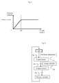
- the kinetic energy recoverable in deceleration is quantified from a vehicle simulation model or measurements on a real vehicle. Assuming a consistent average deceleration with a dynamic rolling, it is possible to evaluate the recoverable energy for each speed such as the curve of the figure 3 the watch.
- this one is calculated dynamically according to the evolution of the speed of the vehicle and is added to a reserve of available energy for the acceleration .
- this reserve which we call reserve a, is empty and increases as the speed increases.
- the reserve is 0 kJ at 60 km / h, 300 kJ at 90 km / h and 600 kJ at 120 km / h.
- This second reserve which we call reserve b, can thus represent up to 100 kJ. However, it is preferable to minimize it to reduce the impact on consumption during recharging phases.
- the device illustrated on the figure 2 makes it possible to exploit the above stated principle by limiting the usable energy during acceleration, to the sum of the recoverable energy by returning to the initial state (reserve a) and the energy statistically obtained by recharging between two requests for acceleration (reservation b).
- the module 60 comprises a component 69 arranged to calculate a cumulative energy consumption from an instantaneous power indicated by the negative values of the signal 64 as long as the request for energy overload is detected by the signal 70.
- the component 69 generates a signal 71 which represents the energy that has been spent at each moment since the start of the energy overload demand detection.
- the signal 61 developed in this case by means of a component 77 which subtracts the signal 71 from the sum of the signals 67 and 68, then represents a usable energy remaining.
- the detection of a request for energy surcharge constitutes the initial moment of calculation of the energy usable by the reversible chain. of kinetic energy production, that is to say the chain which includes the electric machine.
- the reserve a is empty and the reserve b is 100 kJ.
- the usable energy from the reserve a increases to reach 100 kJ at 60 km / h, 400 kJ at 90 km / h and 700 kJ at 120 km / h.
- the reversible chain consumes a portion of the energy of the reserve b, so that the usable energy decreases.
- the device illustrated by the figure 3 calculates the remaining usable energy by subtracting the energy expenditure of the reversible chain from the usable energy.
- the module 60 comprises a component 72 arranged to calculate a usable power, for example as explained later in the description with reference to the figure 6 .
- the component 72 receives as input the sum of the signals 67 and 68, from which the signal 71 is subtracted so as to generate the signal 61 which in this case indicates an authorized power value that can be directly exploited by the module 40.
- the usable power When the remaining energy is above a threshold, the usable power is maximum. As soon as the remaining energy falls below the threshold, the usable power is limited in proportion to the remaining energy. It is set to zero when the remaining energy is zero and at maximum power when the remaining energy is equal to the threshold.
- the threshold is as low as possible to allow to offer the full power the greater part of the time. Its only function is to gradually reduce the traction power available at the end of the reserve.
- a method of controlling an energy overload in the hybrid vehicle system which comprises an electrical storer and an electrical machine, starts from a reference step 600 from which, a lack of overload demand validates a transition 607 and an overload request detection validates a transition 601.
- the transition 601 activates a step 602 that samples the speed as long as the overload request is valid.
- a step 604 is activated by a transition 603 indicating an instantaneous vehicle speed value obtained by the sampling of step 602 activated by the transition 601 which indicates the demand detection of energy overload.
- Step 604 is scheduled to estimate a recovery potential based on the value indicated by the first transition, i.e., velocity.
- a step 608 is activated by the transition 607 indicating a lack of demand for energy overload. Step 608 is scheduled to estimate a recharged energy in the electrical storage between two energy surcharges.
- a transition 605 is enabled by an available charge value that results from the last recharged energy value that was calculated in step 608 before the transition 601 is committed.
- a transition validation 605 activates a step 606 following step 604. Step 606 is scheduled to generate a usable energy limit for the energy overload as being equal to a sum of the recovery potential and the energy recovery. recharged energy.
- the method starts from the reference step 600 or another reference step 700 to activate a step 702 by the transition 601 or by a transition 701 indicating a demand detection of energy overload.
- Step 702 is scheduled to calculate an energy total spent as a function of a power expended during the overload.
- a step 704 is activated following step 702, particularly by a validated energy-enabled transition 703 that has been calculated or estimated in step 606.
- Step 704 is scheduled to generate a value of energy remaining in order to limit the usable energy for the energy surcharge by subtracting the energy cumulated spent from the sum of the recovery potential and the recharged energy.
- a step 706, activated following step 704, is scheduled to calculate a usable power based on the remaining energy.
- step 706 when the remaining energy is above a threshold, the usable power is maximum. As soon as the remaining energy falls below the threshold, the usable power is limited in proportion to the remaining energy. It is set to zero when the remaining energy is zero and at maximum power when the remaining energy is equal to the threshold.
- this step makes it possible to vary the power progressively so as not to harm the approval of the vehicle.
- step 604 the recovery potential is estimated from the kinetic energy of the vehicle based on observations of the curve represented in FIG. figure 3 .
- the usable power to improve the dynamic performance of the vehicle is determined so as to apply the maximum power from the beginning of the acceleration request. It does not matter then that the torque supply of the reversible chain is limited in time by an available quantity of energy or that the full power can not be applied until the end of the acceleration. The driver's expectations concerning the acceleration capacity of the vehicle, directly related to the torque that the traction chain can provide, is satisfied. An appreciable degree of robustness and optimization of the dynamic performance of the vehicle is thus achieved.
Landscapes
- Engineering & Computer Science (AREA)
- Transportation (AREA)
- Mechanical Engineering (AREA)
- Chemical & Material Sciences (AREA)
- Combustion & Propulsion (AREA)
- Automation & Control Theory (AREA)
- Power Engineering (AREA)
- Electric Propulsion And Braking For Vehicles (AREA)
Applications Claiming Priority (1)
| Application Number | Priority Date | Filing Date | Title |
|---|---|---|---|
| FR0852397A FR2930086B1 (fr) | 2008-04-10 | 2008-04-10 | Procede et dispositif de controle d'une surcharge energetique |
Publications (2)
| Publication Number | Publication Date |
|---|---|
| EP2108558A1 true EP2108558A1 (de) | 2009-10-14 |
| EP2108558B1 EP2108558B1 (de) | 2019-06-12 |
Family
ID=40243882
Family Applications (1)
| Application Number | Title | Priority Date | Filing Date |
|---|---|---|---|
| EP09157674.4A Active EP2108558B1 (de) | 2008-04-10 | 2009-04-09 | Verfahren und Vorrichtung zur Kontrolle einer energetischen Belastung |
Country Status (2)
| Country | Link |
|---|---|
| EP (1) | EP2108558B1 (de) |
| FR (1) | FR2930086B1 (de) |
Cited By (2)
| Publication number | Priority date | Publication date | Assignee | Title |
|---|---|---|---|---|
| WO2011103905A1 (de) * | 2010-02-25 | 2011-09-01 | Dr. Ing. H.C. F. Porsche Aktiengesellschaft | Anzeigevorrichtung eines kraftfahrzeugs und verfahren zum generieren einer betriebsmodusanzeige auf einer anzeigevorrichtung eines kraftfahrzeugs |
| FR3013661A1 (fr) * | 2013-11-28 | 2015-05-29 | Peugeot Citroen Automobiles Sa | Procede de commande d'un groupe motopropulseur hybride pour assurer l'operativite d'une fonction de motorisation |
Citations (5)
| Publication number | Priority date | Publication date | Assignee | Title |
|---|---|---|---|---|
| DE4430670A1 (de) * | 1993-09-02 | 1995-03-09 | Nippon Denso Co | Steuervorrichtung für einen elektrischen Generator/Motor für einen Verbrennungsmotor |
| JP2004120865A (ja) * | 2002-09-25 | 2004-04-15 | Daihatsu Motor Co Ltd | ハイブリッド車両の走行駆動制御装置 |
| US20050088139A1 (en) * | 1998-04-21 | 2005-04-28 | Frank Andrew A. | Method for controlling the operating characteristics of a hybrid electric vehicle |
| US6889126B2 (en) | 2003-04-22 | 2005-05-03 | Nissan Motor Co., Ltd. | Drive force control for hybrid electric vehicle |
| US20070029119A1 (en) * | 2005-08-02 | 2007-02-08 | Ford Global Technologies, Llc | Method and system for determining final desired wheel power in a hybrid electric vehicle powertrain |
-
2008
- 2008-04-10 FR FR0852397A patent/FR2930086B1/fr not_active Expired - Fee Related
-
2009
- 2009-04-09 EP EP09157674.4A patent/EP2108558B1/de active Active
Patent Citations (5)
| Publication number | Priority date | Publication date | Assignee | Title |
|---|---|---|---|---|
| DE4430670A1 (de) * | 1993-09-02 | 1995-03-09 | Nippon Denso Co | Steuervorrichtung für einen elektrischen Generator/Motor für einen Verbrennungsmotor |
| US20050088139A1 (en) * | 1998-04-21 | 2005-04-28 | Frank Andrew A. | Method for controlling the operating characteristics of a hybrid electric vehicle |
| JP2004120865A (ja) * | 2002-09-25 | 2004-04-15 | Daihatsu Motor Co Ltd | ハイブリッド車両の走行駆動制御装置 |
| US6889126B2 (en) | 2003-04-22 | 2005-05-03 | Nissan Motor Co., Ltd. | Drive force control for hybrid electric vehicle |
| US20070029119A1 (en) * | 2005-08-02 | 2007-02-08 | Ford Global Technologies, Llc | Method and system for determining final desired wheel power in a hybrid electric vehicle powertrain |
Cited By (2)
| Publication number | Priority date | Publication date | Assignee | Title |
|---|---|---|---|---|
| WO2011103905A1 (de) * | 2010-02-25 | 2011-09-01 | Dr. Ing. H.C. F. Porsche Aktiengesellschaft | Anzeigevorrichtung eines kraftfahrzeugs und verfahren zum generieren einer betriebsmodusanzeige auf einer anzeigevorrichtung eines kraftfahrzeugs |
| FR3013661A1 (fr) * | 2013-11-28 | 2015-05-29 | Peugeot Citroen Automobiles Sa | Procede de commande d'un groupe motopropulseur hybride pour assurer l'operativite d'une fonction de motorisation |
Also Published As
| Publication number | Publication date |
|---|---|
| FR2930086A1 (fr) | 2009-10-16 |
| FR2930086B1 (fr) | 2012-04-20 |
| EP2108558B1 (de) | 2019-06-12 |
Similar Documents
| Publication | Publication Date | Title |
|---|---|---|
| FR2994027A1 (fr) | Vehicule comprenant une batterie et des moyens de determination d'une puissance maximale admissible pour la batterie, et procede correspondant | |
| WO2012175857A1 (fr) | Procede d'aide au pilotage d'un vehicule automobile en vue d'optimiser l'utilisation de la reserve d'energie | |
| FR2851516A1 (fr) | Procede de commande de systeme electrique de vehicule | |
| FR2966412A1 (fr) | Appareil de commande de production d'energie de vehicule | |
| FR2875652A1 (fr) | Procede et systeme pour commander la puissance a appliquer a des charges electriques | |
| WO2016207528A1 (fr) | Procédé de commande d'un facteur d'équivalence énergétique pour un véhicule automobile hybride | |
| FR2967841A1 (fr) | Dispositif de controle de charge | |
| FR2994546A1 (fr) | Procede de limitation de couple d'une machine electrique de vehicule hybride comportant un systeme de controle de vitesse | |
| WO2019122696A1 (fr) | Procédé de contrôle d'un convertisseur de courant continu dans un réseau de bord d'un véhicule automobile | |
| FR2856109A1 (fr) | Systeme de commande de puissance pour un vehicule sur lequel est monte un moteur avec turbocompresseur | |
| FR3028109A1 (fr) | Procede de gestion de l'etat de charge d'une batterie de traction d'un vehicule hybride. | |
| FR2990672A1 (fr) | Procede et dispositif pour la commande d'un moteur a combustion interne | |
| WO2010034930A1 (fr) | Procede et dispositif de controle d'un stockeur d'energie pour vehicule hybride | |
| EP2108558B1 (de) | Verfahren und Vorrichtung zur Kontrolle einer energetischen Belastung | |
| EP2936651A1 (de) | Stromkreis für ein kraftfahrzeug | |
| FR2965128A1 (fr) | Procede et dispositif de gestion d'un generateur d'un systeme de recuperation d'energie d'un vehicule automobile | |
| FR3015411A1 (fr) | Procede de calcul de consigne de couple pour une machine electrique couplee a un moteur thermique d'un vehicule hybride | |
| EP2271532B1 (de) | Verfahren zur steuerung der beschleunigung eines hybridfahrzeugs | |
| FR3001684A1 (fr) | Procede de gestion de la recuperation d'energie pour un vehicule hybride comportant un systeme de regulation ou de limitation de vitesse | |
| FR3074770B1 (fr) | Procede de generation de sensations de conduite | |
| FR3114538A1 (fr) | Procédé de chauffage d’un habitacle de véhicule électrique équipé d’un prolongateur d’autonomie | |
| FR2990077A1 (fr) | Dispositif de supervision de la charge d'une batterie de vehicule automobile | |
| EP2113435B1 (de) | Verfahren und Vorrichtung zur Steuerung eines Energiespeichers für ein Hybridfahrzeug | |
| FR2783768A1 (fr) | Procede de commande d'un vehicule hybride a transmission electrique serie | |
| WO2011018576A2 (fr) | Procédé de contrôle d'une unité de moteur électrique de propulsion d'un véhicule |
Legal Events
| Date | Code | Title | Description |
|---|---|---|---|
| PUAI | Public reference made under article 153(3) epc to a published international application that has entered the european phase |
Free format text: ORIGINAL CODE: 0009012 |
|
| AK | Designated contracting states |
Kind code of ref document: A1 Designated state(s): AT BE BG CH CY CZ DE DK EE ES FI FR GB GR HR HU IE IS IT LI LT LU LV MC MK MT NL NO PL PT RO SE SI SK TR |
|
| 17P | Request for examination filed |
Effective date: 20100331 |
|
| 17Q | First examination report despatched |
Effective date: 20100503 |
|
| RAP1 | Party data changed (applicant data changed or rights of an application transferred) |
Owner name: PSA AUTOMOBILES SA |
|
| REG | Reference to a national code |
Ref country code: DE Ref legal event code: R079 Ref document number: 602009058681 Country of ref document: DE Free format text: PREVIOUS MAIN CLASS: B60W0020000000 Ipc: B60W0010260000 |
|
| GRAP | Despatch of communication of intention to grant a patent |
Free format text: ORIGINAL CODE: EPIDOSNIGR1 |
|
| STAA | Information on the status of an ep patent application or granted ep patent |
Free format text: STATUS: GRANT OF PATENT IS INTENDED |
|
| RIC1 | Information provided on ipc code assigned before grant |
Ipc: B60W 20/00 20160101ALI20181210BHEP Ipc: B60W 10/26 20060101AFI20181210BHEP Ipc: B60W 30/18 20120101ALI20181210BHEP Ipc: H02J 7/14 20060101ALI20181210BHEP Ipc: B60W 10/08 20060101ALI20181210BHEP |
|
| INTG | Intention to grant announced |
Effective date: 20190111 |
|
| GRAS | Grant fee paid |
Free format text: ORIGINAL CODE: EPIDOSNIGR3 |
|
| GRAA | (expected) grant |
Free format text: ORIGINAL CODE: 0009210 |
|
| STAA | Information on the status of an ep patent application or granted ep patent |
Free format text: STATUS: THE PATENT HAS BEEN GRANTED |
|
| AK | Designated contracting states |
Kind code of ref document: B1 Designated state(s): AT BE BG CH CY CZ DE DK EE ES FI FR GB GR HR HU IE IS IT LI LT LU LV MC MK MT NL NO PL PT RO SE SI SK TR |
|
| REG | Reference to a national code |
Ref country code: GB Ref legal event code: FG4D Free format text: NOT ENGLISH |
|
| REG | Reference to a national code |
Ref country code: CH Ref legal event code: EP |
|
| REG | Reference to a national code |
Ref country code: AT Ref legal event code: REF Ref document number: 1142161 Country of ref document: AT Kind code of ref document: T Effective date: 20190615 |
|
| REG | Reference to a national code |
Ref country code: DE Ref legal event code: R096 Ref document number: 602009058681 Country of ref document: DE |
|
| REG | Reference to a national code |
Ref country code: GB Ref legal event code: 746 Effective date: 20190617 Ref country code: IE Ref legal event code: FG4D Free format text: LANGUAGE OF EP DOCUMENT: FRENCH |
|
| REG | Reference to a national code |
Ref country code: NL Ref legal event code: MP Effective date: 20190612 |
|
| REG | Reference to a national code |
Ref country code: LT Ref legal event code: MG4D |
|
| PG25 | Lapsed in a contracting state [announced via postgrant information from national office to epo] |
Ref country code: NO Free format text: LAPSE BECAUSE OF FAILURE TO SUBMIT A TRANSLATION OF THE DESCRIPTION OR TO PAY THE FEE WITHIN THE PRESCRIBED TIME-LIMIT Effective date: 20190912 Ref country code: FI Free format text: LAPSE BECAUSE OF FAILURE TO SUBMIT A TRANSLATION OF THE DESCRIPTION OR TO PAY THE FEE WITHIN THE PRESCRIBED TIME-LIMIT Effective date: 20190612 Ref country code: SE Free format text: LAPSE BECAUSE OF FAILURE TO SUBMIT A TRANSLATION OF THE DESCRIPTION OR TO PAY THE FEE WITHIN THE PRESCRIBED TIME-LIMIT Effective date: 20190612 Ref country code: HR Free format text: LAPSE BECAUSE OF FAILURE TO SUBMIT A TRANSLATION OF THE DESCRIPTION OR TO PAY THE FEE WITHIN THE PRESCRIBED TIME-LIMIT Effective date: 20190612 Ref country code: LT Free format text: LAPSE BECAUSE OF FAILURE TO SUBMIT A TRANSLATION OF THE DESCRIPTION OR TO PAY THE FEE WITHIN THE PRESCRIBED TIME-LIMIT Effective date: 20190612 Ref country code: ES Free format text: LAPSE BECAUSE OF FAILURE TO SUBMIT A TRANSLATION OF THE DESCRIPTION OR TO PAY THE FEE WITHIN THE PRESCRIBED TIME-LIMIT Effective date: 20190612 |
|
| PG25 | Lapsed in a contracting state [announced via postgrant information from national office to epo] |
Ref country code: BG Free format text: LAPSE BECAUSE OF FAILURE TO SUBMIT A TRANSLATION OF THE DESCRIPTION OR TO PAY THE FEE WITHIN THE PRESCRIBED TIME-LIMIT Effective date: 20190912 Ref country code: LV Free format text: LAPSE BECAUSE OF FAILURE TO SUBMIT A TRANSLATION OF THE DESCRIPTION OR TO PAY THE FEE WITHIN THE PRESCRIBED TIME-LIMIT Effective date: 20190612 Ref country code: GR Free format text: LAPSE BECAUSE OF FAILURE TO SUBMIT A TRANSLATION OF THE DESCRIPTION OR TO PAY THE FEE WITHIN THE PRESCRIBED TIME-LIMIT Effective date: 20190913 |
|
| REG | Reference to a national code |
Ref country code: AT Ref legal event code: MK05 Ref document number: 1142161 Country of ref document: AT Kind code of ref document: T Effective date: 20190612 |
|
| REG | Reference to a national code |
Ref country code: DE Ref legal event code: R084 Ref document number: 602009058681 Country of ref document: DE |
|
| PG25 | Lapsed in a contracting state [announced via postgrant information from national office to epo] |
Ref country code: SK Free format text: LAPSE BECAUSE OF FAILURE TO SUBMIT A TRANSLATION OF THE DESCRIPTION OR TO PAY THE FEE WITHIN THE PRESCRIBED TIME-LIMIT Effective date: 20190612 Ref country code: CZ Free format text: LAPSE BECAUSE OF FAILURE TO SUBMIT A TRANSLATION OF THE DESCRIPTION OR TO PAY THE FEE WITHIN THE PRESCRIBED TIME-LIMIT Effective date: 20190612 Ref country code: RO Free format text: LAPSE BECAUSE OF FAILURE TO SUBMIT A TRANSLATION OF THE DESCRIPTION OR TO PAY THE FEE WITHIN THE PRESCRIBED TIME-LIMIT Effective date: 20190612 Ref country code: EE Free format text: LAPSE BECAUSE OF FAILURE TO SUBMIT A TRANSLATION OF THE DESCRIPTION OR TO PAY THE FEE WITHIN THE PRESCRIBED TIME-LIMIT Effective date: 20190612 Ref country code: AT Free format text: LAPSE BECAUSE OF FAILURE TO SUBMIT A TRANSLATION OF THE DESCRIPTION OR TO PAY THE FEE WITHIN THE PRESCRIBED TIME-LIMIT Effective date: 20190612 Ref country code: NL Free format text: LAPSE BECAUSE OF FAILURE TO SUBMIT A TRANSLATION OF THE DESCRIPTION OR TO PAY THE FEE WITHIN THE PRESCRIBED TIME-LIMIT Effective date: 20190612 Ref country code: PT Free format text: LAPSE BECAUSE OF FAILURE TO SUBMIT A TRANSLATION OF THE DESCRIPTION OR TO PAY THE FEE WITHIN THE PRESCRIBED TIME-LIMIT Effective date: 20191014 |
|
| PG25 | Lapsed in a contracting state [announced via postgrant information from national office to epo] |
Ref country code: IT Free format text: LAPSE BECAUSE OF FAILURE TO SUBMIT A TRANSLATION OF THE DESCRIPTION OR TO PAY THE FEE WITHIN THE PRESCRIBED TIME-LIMIT Effective date: 20190612 Ref country code: IS Free format text: LAPSE BECAUSE OF FAILURE TO SUBMIT A TRANSLATION OF THE DESCRIPTION OR TO PAY THE FEE WITHIN THE PRESCRIBED TIME-LIMIT Effective date: 20191012 |
|
| REG | Reference to a national code |
Ref country code: DE Ref legal event code: R097 Ref document number: 602009058681 Country of ref document: DE |
|
| PG25 | Lapsed in a contracting state [announced via postgrant information from national office to epo] |
Ref country code: TR Free format text: LAPSE BECAUSE OF FAILURE TO SUBMIT A TRANSLATION OF THE DESCRIPTION OR TO PAY THE FEE WITHIN THE PRESCRIBED TIME-LIMIT Effective date: 20190612 |
|
| PLBE | No opposition filed within time limit |
Free format text: ORIGINAL CODE: 0009261 |
|
| STAA | Information on the status of an ep patent application or granted ep patent |
Free format text: STATUS: NO OPPOSITION FILED WITHIN TIME LIMIT |
|
| PG25 | Lapsed in a contracting state [announced via postgrant information from national office to epo] |
Ref country code: PL Free format text: LAPSE BECAUSE OF FAILURE TO SUBMIT A TRANSLATION OF THE DESCRIPTION OR TO PAY THE FEE WITHIN THE PRESCRIBED TIME-LIMIT Effective date: 20190612 Ref country code: DK Free format text: LAPSE BECAUSE OF FAILURE TO SUBMIT A TRANSLATION OF THE DESCRIPTION OR TO PAY THE FEE WITHIN THE PRESCRIBED TIME-LIMIT Effective date: 20190612 |
|
| 26N | No opposition filed |
Effective date: 20200313 |
|
| PG25 | Lapsed in a contracting state [announced via postgrant information from national office to epo] |
Ref country code: SI Free format text: LAPSE BECAUSE OF FAILURE TO SUBMIT A TRANSLATION OF THE DESCRIPTION OR TO PAY THE FEE WITHIN THE PRESCRIBED TIME-LIMIT Effective date: 20190612 Ref country code: IS Free format text: LAPSE BECAUSE OF FAILURE TO SUBMIT A TRANSLATION OF THE DESCRIPTION OR TO PAY THE FEE WITHIN THE PRESCRIBED TIME-LIMIT Effective date: 20200224 |
|
| PG2D | Information on lapse in contracting state deleted |
Ref country code: IS |
|
| PG25 | Lapsed in a contracting state [announced via postgrant information from national office to epo] |
Ref country code: IS Free format text: LAPSE BECAUSE OF FAILURE TO SUBMIT A TRANSLATION OF THE DESCRIPTION OR TO PAY THE FEE WITHIN THE PRESCRIBED TIME-LIMIT Effective date: 20191112 |
|
| PG25 | Lapsed in a contracting state [announced via postgrant information from national office to epo] |
Ref country code: MC Free format text: LAPSE BECAUSE OF FAILURE TO SUBMIT A TRANSLATION OF THE DESCRIPTION OR TO PAY THE FEE WITHIN THE PRESCRIBED TIME-LIMIT Effective date: 20190612 |
|
| REG | Reference to a national code |
Ref country code: CH Ref legal event code: PL |
|
| PG25 | Lapsed in a contracting state [announced via postgrant information from national office to epo] |
Ref country code: LI Free format text: LAPSE BECAUSE OF NON-PAYMENT OF DUE FEES Effective date: 20200430 Ref country code: CH Free format text: LAPSE BECAUSE OF NON-PAYMENT OF DUE FEES Effective date: 20200430 Ref country code: LU Free format text: LAPSE BECAUSE OF NON-PAYMENT OF DUE FEES Effective date: 20200409 |
|
| REG | Reference to a national code |
Ref country code: BE Ref legal event code: MM Effective date: 20200430 |
|
| PG25 | Lapsed in a contracting state [announced via postgrant information from national office to epo] |
Ref country code: BE Free format text: LAPSE BECAUSE OF NON-PAYMENT OF DUE FEES Effective date: 20200430 |
|
| PG25 | Lapsed in a contracting state [announced via postgrant information from national office to epo] |
Ref country code: IE Free format text: LAPSE BECAUSE OF NON-PAYMENT OF DUE FEES Effective date: 20200409 |
|
| PG25 | Lapsed in a contracting state [announced via postgrant information from national office to epo] |
Ref country code: MT Free format text: LAPSE BECAUSE OF FAILURE TO SUBMIT A TRANSLATION OF THE DESCRIPTION OR TO PAY THE FEE WITHIN THE PRESCRIBED TIME-LIMIT Effective date: 20190612 Ref country code: CY Free format text: LAPSE BECAUSE OF FAILURE TO SUBMIT A TRANSLATION OF THE DESCRIPTION OR TO PAY THE FEE WITHIN THE PRESCRIBED TIME-LIMIT Effective date: 20190612 |
|
| PG25 | Lapsed in a contracting state [announced via postgrant information from national office to epo] |
Ref country code: MK Free format text: LAPSE BECAUSE OF FAILURE TO SUBMIT A TRANSLATION OF THE DESCRIPTION OR TO PAY THE FEE WITHIN THE PRESCRIBED TIME-LIMIT Effective date: 20190612 |
|
| PGFP | Annual fee paid to national office [announced via postgrant information from national office to epo] |
Ref country code: GB Payment date: 20230321 Year of fee payment: 15 |
|
| REG | Reference to a national code |
Ref country code: DE Ref legal event code: R081 Ref document number: 602009058681 Country of ref document: DE Owner name: STELLANTIS AUTO SAS, FR Free format text: FORMER OWNER: PSA AUTOMOBILES SA, POISSY, FR |
|
| GBPC | Gb: european patent ceased through non-payment of renewal fee |
Effective date: 20240409 |
|
| PG25 | Lapsed in a contracting state [announced via postgrant information from national office to epo] |
Ref country code: GB Free format text: LAPSE BECAUSE OF NON-PAYMENT OF DUE FEES Effective date: 20240409 |
|
| PG25 | Lapsed in a contracting state [announced via postgrant information from national office to epo] |
Ref country code: GB Free format text: LAPSE BECAUSE OF NON-PAYMENT OF DUE FEES Effective date: 20240409 |
|
| PGFP | Annual fee paid to national office [announced via postgrant information from national office to epo] |
Ref country code: DE Payment date: 20250319 Year of fee payment: 17 |
|
| PGFP | Annual fee paid to national office [announced via postgrant information from national office to epo] |
Ref country code: FR Payment date: 20260319 Year of fee payment: 18 |