EP2108586A1 - Teleskopmast für den Weltraum mit Verriegelung unter Restspanndruck - Google Patents
Teleskopmast für den Weltraum mit Verriegelung unter Restspanndruck Download PDFInfo
- Publication number
- EP2108586A1 EP2108586A1 EP09157386A EP09157386A EP2108586A1 EP 2108586 A1 EP2108586 A1 EP 2108586A1 EP 09157386 A EP09157386 A EP 09157386A EP 09157386 A EP09157386 A EP 09157386A EP 2108586 A1 EP2108586 A1 EP 2108586A1
- Authority
- EP
- European Patent Office
- Prior art keywords
- segment
- axial
- deployment
- distal
- shoulder
- Prior art date
- Legal status (The legal status is an assumption and is not a legal conclusion. Google has not performed a legal analysis and makes no representation as to the accuracy of the status listed.)
- Granted
Links
Images



Classifications
-
- E—FIXED CONSTRUCTIONS
- E04—BUILDING
- E04H—BUILDINGS OR LIKE STRUCTURES FOR PARTICULAR PURPOSES; SWIMMING OR SPLASH BATHS OR POOLS; MASTS; FENCING; TENTS OR CANOPIES, IN GENERAL
- E04H12/00—Towers; Masts or poles; Chimney stacks; Water-towers; Methods of erecting such structures
- E04H12/18—Towers; Masts or poles; Chimney stacks; Water-towers; Methods of erecting such structures movable or with movable sections, e.g. rotatable or telescopic
- E04H12/182—Towers; Masts or poles; Chimney stacks; Water-towers; Methods of erecting such structures movable or with movable sections, e.g. rotatable or telescopic telescopic
-
- B—PERFORMING OPERATIONS; TRANSPORTING
- B64—AIRCRAFT; AVIATION; COSMONAUTICS
- B64G—COSMONAUTICS; VEHICLES OR EQUIPMENT THEREFOR
- B64G1/00—Cosmonautic vehicles
- B64G1/22—Parts of, or equipment specially adapted for fitting in or to, cosmonautic vehicles
- B64G1/222—Parts of, or equipment specially adapted for fitting in or to, cosmonautic vehicles for deploying structures between a stowed and deployed state
- B64G1/2221—Parts of, or equipment specially adapted for fitting in or to, cosmonautic vehicles for deploying structures between a stowed and deployed state characterised by the manner of deployment
- B64G1/2226—Telescoping
Definitions
- the invention relates to a telescopic mast for a space system (for example an artificial space satellite, a space probe, a space vehicle, etc.).
- a space system for example an artificial space satellite, a space probe, a space vehicle, etc.
- a space mast can be used for example to carry a sensor (magnetometer, laser, camera, transmitter, receiver ...) at its distal end, so as to move it away from the main body of the space system, to make measurements on this body main and / or out of its influence (especially of electromagnetic nature (parasites), optical (masking), gravitational or inertial).
- a sensor magnetometer, laser, camera, transmitter, receiver
- One of the solutions envisaged is therefore to provide a telescopic mast comprising a plurality of coaxial cylindrical segments radially nested in each other. In the retracted initial position, at launch, the segments are retracted into each other so as to occupy a reduced axial size.
- a motorized mechanism for axial deployment of the segments makes it possible to deploy them to an extended position where they are fully deployed in axial extension from one another, the mast then having its nominal operating length.
- the telescopic mast must have sufficient flexural stiffness, with a first mode specific to a natural frequency greater than 1 Hz. Now, obtaining such a stiffness is reflected in the structures proposed so far by a mass per unit length deployed greater than 3 kg / m. Conversely, the lighter versions of such telescopic masts proposed until now have a weight per unit length deployed which remains greater than 0.9 kg / m, and a first clean mode bending to about 0.5 Hz.
- the invention aims to propose a telescopic mast with improved dimensional and mechanical characteristics for a reduced mass.
- the invention aims to provide a space telescopic mast that can have a mass per unit length of deployed less than 0.75 kg / m, allowing its integration on board light space systems (such as satellites of less than 250 kg ), with a first own bending mode at a natural frequency greater than 1 Hz.
- the invention also aims to provide a telescopic mast space which is also particularly resistant to stress or stress variations, thermal expansion and thermoelastic effects, and retains its dimensional and mechanical characteristics.
- a telescopic mast according to the invention has a very high flexural stiffness in the deployed state, a predetermined length in the deployed state of high precision and perfectly reproducible with great reliability, without play, for a low mass linear to the deployed state, and is likely to retain its dimensional and mechanical properties by undergoing efforts or variations of forces, thermal dilatation or thermoelastic effects. Furthermore, the presence of a residual axial elastic clamping stress between the segments allows a hyperstatic type of assembly between the different segments and the motorized deployment mechanism, since a certain relative axial displacement is allowed by the locks against axial clamping stress. In addition, the value of the permanent residual stress of axial clamping can be adjusted to a predetermined value depending on the application.
- each axial clamping spring is a compression spring tending to move away the drive flange of the proximal shoulder.
- a mast according to the invention is also characterized in that each movable segment has a tubular main body of radial dimension smaller than the radial dimension of the drive flange, and in that each hooking finger of the mobile segment extends axially outside the tubular main body and is formed of a resiliently flexible rod at least radially inwardly having a free end forming a hook, so that the hooking of each picking finger of the movable segment with said locking surface of the distal shoulder of the fixed segment intervenes by elastic deformation in flexion radially towards the inside of the picking finger.
- each picking finger has at least one inclined range relative to the axis of the picking finger, this inclined bearing extending radially outwardly beyond the rod forming the hooking finger and being adapted to come into contact with an inner wall integral with the distal shoulder of the fixed segment, said inclined reach extending radially to a distance from the axis of the mast greater than the distance between said inner wall and the axis of the mast, so as to cause, under the effect of the deployment, the elastic bending deformation of the hooking finger.
- the distance between the rod of the picking finger and the axis of the mast is less than the distance between said inner wall and the axis of the mast, so that the rod forming the picking finger can engage inside (radially) of this inner wall, until the hooking intervenes.
- the inclined range of the picking finger forms the part of the hook which thus allows to control the elastic deformation in bending towards the inside of the hooking finger.
- This inclined range is connected to the rod forming the main part of the picking finger by a radial shoulder forming a hook.
- this radial shoulder and the locking range of the fixed segment extend in a transverse radial plane, the hooking performs an irreversible locking (except to manually deform the flexing finger radially inwards).
- a telescopic mast according to the invention is indeed advantageously of the single deployment type.
- each hooking finger and said locking range of the fixed segment are adapted to form a normally irreversible locking of the hooking finger with respect to the distal shoulder of the fixed segment.
- the motorized mechanism for deploying a mast according to the invention may be the subject of various alternative embodiments, the shoulders forming axial abutment between the segments and the axially elastic locking latches being compatible with most embodiments of the mechanisms.
- motorized axial deployment that can be envisaged. That being so, advantageously and according to the invention, the motorized mechanism for axial deployment of the segments comprises a central axial worm and, for each segment to be deployed, meshing fingers carried by the drive flange and extending radially. inwards to be able to cooperate by meshing with this central screw.
- each proximal shoulder and each distal shoulder comprise a wall in the form of plane ring extending in a transverse radial plane to the axis of deployment.
- the two shoulders come into contact with each other at least by portions in contact with these radial planar crowns.
- the mobile segment extends radially inside the fixed segment, the proximal shoulder of the movable segment extending radially outwardly relative to a cylindrical outer wall of the main body of the segment.
- movable, the distal shoulder of the fixed segment extending radially inwardly relative to a cylindrical inner wall of the main body of the fixed segment.
- the segment forming the distal end of the mast in the deployed state is the segment which has the smallest radial dimensions and which is deployed first, the other segments then being deployed successively, from the smallest to the largest.
- the axial locking mechanism comprises a control rod guided in axial translation with respect to the distal shoulder of the intermediate segment, and adapted to be pushed back by the drive flange of the immediately adjacent mobile segment deployed. relative to the intermediate segment, at the end of deployment of this mobile segment, so as to release a locking ball carried by the intermediate segment and extending radially outwardly, in the locking position, being housed in a recess of the segment immediately adjacent outward to this intermediate segment.
- each segment comprises a main body formed of a cylindrical tube of revolution of composite material compatible with the space environment.
- the invention also relates to a mast characterized in combination by all or part of the characteristics mentioned above or below.
- the telescopic mast 1 is represented on the figure 1 in fully retracted position, that is to say in the state where it is at the time of launch of the space system.
- this telescopic mast comprises a plurality of coaxial hollow cylindrical segments radially nested in each other, namely: an outer segment 2 of larger radial dimensions acting as outer casing of the telescopic mast in the retracted position, and mounted integral with supports 3 for anchoring the telescopic mast 1 on a chassis (not shown) of the space system; an inner segment 4 of smaller radial dimensions; and intermediate segments 5 radially interposed between the inner segment 4 and the outer segment 2.
- a motorized mechanism 6, 7 for axial deployment of the segments 4, 5 with respect to each other and with respect to the outer segment 2 is associated with the mast.
- telescopic carried at one end, said proximal end 8, of the outer segment 2.
- each cylindrical segment 2, 4, 5 is not necessarily symmetrical about its axis but may instead have a polygonal or elliptical or other base. That being so, preferably and according to the invention, as shown in the figures, each segment 2, 4, 5 cylindrical is formed of a cylindrical tubular section of hollow revolution.
- proximal designates a portion extending on the side of one end of the telescopic mast which is anchored to a frame (in particular on a not shown frame of the space system carrying the mast), bearing in general also the mechanism 6, 7 motorized deployment, while the term “distal” means a portion extending from the opposite side, that is to say the side of the free end of the mast 1 telescopic in the state deployed.
- the telescopic mast 1 thus comprises a proximal segment forming its proximal end, a distal segment forming its free distal end, and intermediate segments extending, in the deployed position, between the proximal segment and the distal segment.
- the outer segment 2 constitutes the proximal segment 2 of the telescopic mast 1
- the inner segment 4 constitutes the distal segment 4 of the telescopic mast 1.
- the distal segment 4 begins to deploy along the axis of deployment which coincides with the axis of the different segments 2, 4, 5 as shown figure 2 .
- the distal segment 4 is locked relative to the immediately adjacent intermediate segment 5 which is still fixed, and this locking causes a release of this immediately adjacent intermediate segment 5 which can itself begin to unfold axially.
- the telescopic mast 1 has the appearance shown figure 4 .
- the distal end 9 of the distal segment 4 which constitutes the distal end of the deployed mast 1 may carry a member (not shown) such as a sensor (magnetometer, laser, camera, transmitter, receiver ).
- a cable or bundle of cables may be provided to connect this sensor to the proximal end 8 so as to allow its connection to the other elements of the space system.
- the motorized deployment mechanism 6, 7 comprises, in the embodiment shown, a geared motor 6 coupled to a worm 7 extending axially along the axis of deployment inside the distal segment 4 over a length corresponding to the length of each segment 2, 4, 5.
- Each segment 4, 5 to be deployed comprises a tubular hollow cylindrical main body 11 having a cylindrical inner wall 19 and a cylindrical outer wall 20, a proximal end ring 10 integral with the body 11, a distal end ring 12 secured to the body 11, and a drive flange 13 connected at the proximal end ring 10 by resilient blades 14.
- the proximal segment 2 also comprises a tubular cylindrical main body 11 and a distal end ring 12, but is free of a drive flange, and its proximal end 8 does not have a ring similar to that of the other segments 4, 5.
- the distal end 9 of the distal segment 4 is not necessarily provided with a distal end ring 12 similar to that of the proximal segment 2 and intermediate segments 5.
- the drive flange 13 carries meshing fingers 16 extending radially inwards so as to cooperate with the worm 7 and to be driven axially by the worm in the direction of deployment when it is put into operation. rotation by the geared motor 6.
- the drive flange 13 extends upstream of the proximal end ring (relative to the direction of deployment of the segments 4, 5) and is kept at a distance from the latter by the elastic blades 14 and springs. helical compressors 15 interposed between this drive flange 13 and the proximal end ring.
- the rotation of the worm 7 drives the meshing fingers 16, and therefore the drive flange 13 and, via the elastic blades 14 and the compression springs 15, the proximal end ring 10 and thus the entire mobile segment. Nevertheless, from a certain value of axial approach force exerted between the drive flange 13 and the proximal end ring 10, these two elements can move toward each other axially against each other. axial elastic return imparted by the elastic blades 14 and the springs 15.
- the drive flange 13 and the proximal end ring 10 have an outer wall 17, respectively 18, cylindrical about the axis of deployment, and these walls 17, 18 have an outer diameter corresponding to the internal diameter of the inner wall. 19 of the main body 11 of the fixed segment, so that the mobile segment is guided axially during deployment in the fixed segment by these walls 17, 18 of the drive flange 13 and the proximal end ring 10 which slide in the inner wall 19.
- the distal end ring 12 of the fixed segment is fitted on the main body 11, and has for this purpose a skirt 21 which is engaged in the distal end of the inner wall 19 of the main body 11.
- the skirt 21 extends on a short axial length, and itself has a cylindrical inner wall 22 whose diameter is also greater than the diameter of the outer wall 20 of the main body of the movable segment. In this way, a radial clearance is also provided between the skirt 21 and the main body 11 of the movable segment.
- the skirt 21 forms, at its proximal axial end (that is to say oriented towards the proximal end of the fixed segment), a radial shoulder, called the distal shoulder 24, integral with the fixed segment and disposed at the distal end of the this last.
- This distal shoulder 24 is oriented towards the proximal end of the fixed segment, that is to say in the opposite direction to the direction of deployment.
- the proximal end ring 10 of the movable segment also forms a radial shoulder, said proximal shoulder 25, integral with the main body 11 of the movable segment, extending radially outside the latter.
- the proximal shoulder 25 is oriented toward the distal end of the movable segment, i.e., in the direction of deployment.
- the distal shoulder 24 of the fixed segment and the proximal shoulder 25 of the mobile segment are adapted to come into contact with each other at the end of deployment of the mobile segment relative to the fixed segment, the proximal shoulder 25 extending upstream of the distal shoulder 24 relative to the direction of deployment, so as to form an axial abutment of deployment of the two segments relative to each other.
- This axial stop prohibits any deployment of the mobile segment beyond a certain axial position of the mobile segment where the two shoulders 24, 25 come into contact with one another.
- these radial shoulders 24, 25 preferably each comprising a wall in the form of a flat ring extending in a transverse plane radially to the axis of deployment impose, when in contact with each other, precise axial positioning, without play of the two segments relative to each other, and ensure perfect alignment of the two segments along the axis of deployment, without play or possibility of inadvertent angular displacement.
- the proximal end ring 10 also comprises a skirt 27 adapted to be fitted into the skirt 21 of the distal end ring 12 of the fixed segment, this skirt 27 of the ring 10 proximal end having a cylindrical outer wall engaging the cylindrical inner wall 22 of the skirt 21 of the distal end ring 12.
- the skirt 27 of the proximal end ring 10 has a chamfer 29 and / or the skirt 21 of the distal end ring 12 has a countersink 30 facilitating the introduction of the skirt 27 into the skirt 21
- the two skirts 21, 27 in contact by their cylindrical wall also have the effect of adjusting the relative axial orientation of the two segments relative to each other and keeping them aligned along the axis of deployment.
- the telescopic mast 1 also comprises locks distributed around the periphery of the junction of two adjacent segments in the deployed position.
- the locks are adapted to print a permanent residual stress of axial elastic clamping of the two shoulders 24, 25 in contact with each other, which allows on the one hand to ensure a shape and precise dimensions to the mast to the other. deployed state as indicated above, on the other hand to allow nevertheless to subject the telescopic mast 1 according to the invention to efforts and variations of efforts, thermal expansion or contraction, various thermoelastic effects, ensuring the maintenance mechanical characteristics, shape and overall dimensions of the mast 1.
- Each latch comprises a hooking finger 23 secured to the drive flange 13 of the corresponding movable segment, extending axially outside the main body 11 of this movable segment in the direction of deployment.
- Each picking finger 23 freely passes through a slot 26 formed through the proximal end ring 10, so as to slide in axial translation freely relative to this ring 10, and therefore with respect to the proximal shoulder 25 formed by this ring 10.
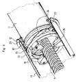
- Each hooking finger 23 comprising a main shaft 32 which has a proximal end secured to the drive flange 13, extends through a compression coil spring 15, passes through a lumen 26 of the proximal end ring 10, and extends axially beyond the proximal shoulder 25 outside the main body 11 of the movable segment over a certain length.
- the hooking finger 23 also has a distal free end 33 extending the main rod 32, this hook-forming end 33 being hooked into engagement with a locking bearing 31 of the distal end ring 12 of the fixed segment. that is to say integral with the distal shoulder 24.
- the end 33 of the picking pin 23 is conical tip-shaped comprising a conical end portion 34 extending a cylindrical portion 35 of greater diameter than diameter of the main stem 32.
- the hooking finger 23 is arranged relative to the drive flange 13 and relative to the proximal end ring 10 of the movable segment so that the main rod 32 engages freely in a groove 42 formed for this purpose in the skirt 21 of the ring 12 distal end of the fixed segment, but can be flexed elastically towards the main body 11 of the movable segment so that its end 33 hook can also pass into the groove 42 of the skirt 21.
- the diameter of the cylindrical portion 35 of the end 33 of the hooking finger 23 is such that it requires the elastic deformation in flexion of the rod 32 radially inward to allow the passage of the end 33 axially in the groove 42 of the skirt 21 of the end stop 12 distal of the fixed segment.
- the locking surface 31 of the distal end ring 12 of the fixed segment is formed for example of a transverse radial plane shoulder extending radially outwardly from the inner wall 22 of the skirt 21, to the distal end of the latter, and oriented in the direction of deployment.
- each hooking finger 23 is also adapted so that the hooking of the finger 23 with said locking surface 31 requires a stroke of axial deployment of the drive flange 13 against the elastic return imparted by the elastic blades. 14 and the helical springs 15 beyond the position where the shoulders 24, 25 come into axial abutment contact, so that, after picking, the elastic blades 14 and the coil springs 15 maintain the two shoulders 24, 25 axially tight. against each other with a permanent residual stress of axial elastic clamping.
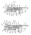
- the figure 6 represents the position in which the two shoulders 24, 25 are not yet in contact with each other, but the end 33 of each hooking finger 23 abuts the chamfered end of the skirt 21.
- this residual permanent stress can be adjusted as a function, on the one hand, of the stiffness of the elastic blades 14 and of the compression springs 15, on the other hand of the displacement imparted to these elastic members 14, 15 to from their form at rest between the axial abutment position of the shoulders 24, 25 and the hooking position of the hooking fingers 23.
- the locking obtained by the hooking fingers 23 also prevents any subsequent inadvertent retraction of the movable segment relative to the fixed segment. This locking is irreversible in that once the mobile segment deployed and the hooking fingers 23 locked, no possibility of dissociation of the hooking fingers 23 relative to the locking surface 31 is provided.
- a plurality of picking fingers 23 are uniformly distributed around the axis of the corresponding movable segment.
- three hooking fingers 23 are provided at 120 ° from each other.
- the fixed segment In the locked position shown figures 8 and 9 , or in a position corresponding to a small axial displacement of the flange 13 in the direction of movement, the fixed segment is released so as to allow its subsequent deployment (unless it is the proximal outer segment 2, which does not have to be deployed).
- the telescopic mast 1 comprises, for each intermediate segment 5, a mechanism 36, 39, 40 for axially locking this intermediate segment 5 with respect to the segment immediately adjacent to it on the side of the proximal segment 2.
- this mechanism 36, 39, 40 of axial blocking being adapted to be released at the end of deployment of the segment 4, 5 immediately adjacent to this intermediate segment 5 on the side of the distal segment 4.
- the mechanism comprises a control rod 36 guided in axial translation relative to the distal end ring 12 of the intermediate fixed segment 5.
- the control rod 36 extends beyond the distal end ring 12 so as to have a proximal end 37 adapted to come into contact with the drive flange 13 of the mobile segment at the end of deployment.
- the control rod 36 has a distal end 38 widened so as to push radially outwardly a ball 39 housed in a recess 40 formed in hollow in the ring 12 of distal end of the adjacent segment outwardly.
- the control rod 36 In the initial position represented figure 10 , the control rod 36 is in its proximal position in which the enlarged end 38 holds the ball 39 in the recess 40, the fixed segment being locked axially.
- the drive flange 13 of the movable segment In the position represented figure 11 , the drive flange 13 of the movable segment has come into contact with the proximal end 37 of the control rod 36, and has pushed the latter axially in the direction of deployment, whereby the ball 39 can move radially towards the the interior disengaging from the recess 40, thereby releasing the distal end ring 12 from the fixed segment relative to the distal end ring 12 of the adjacent segment outwardly to this fixed segment. Therefore, the fixed segment becomes mobile and can then be driven axially in the direction of the Deployment by the rotation of the worm 7.
- the blocking ball 39 is carried by the ring 12 of the distal end of the intermediate fixed segment 5 and driven with the latter, by means of a nut 41 housing the ball 39 allowing its movements in the radial direction between the locking positions and the release.
- return springs may be provided (not shown) on the one hand to recall the control rod 36 in its proximal locking position, on the other hand to recall the ball 39 radially inwardly of in order to guarantee the release when the control rod 36 is pushed back by the drive flange 13.
- the release of the axial blocking mechanism 36, 39, 40 by the drive flange 13 of the mobile segment occurs at the end of deployment of the latter, in a position where the hooking fingers 23 of the mobile segment are already locked against the range 31 of locking.
- the axial locking mechanism 36, 39, 40 is disposed in an axial plane of the distal end ring 12 of the fixed segment which is not an axial plane containing a hooking finger 23 of the segment mobile.
- an end-of-travel device for example a switch, interrupts the geared motor 6.
- the invention can be subject to many different embodiments with respect to the preferred embodiment shown in the figures and described above.
- the shape of the picking fingers may be different.
- other locking devices may be provided to maintain the shoulders in axial contact with each other.
- the meshing fingers, the drive flanges, the end rings can be the subject of different embodiments.
- the invention is also applicable with a deployment mechanism other, for example belt.
Landscapes
- Engineering & Computer Science (AREA)
- Remote Sensing (AREA)
- Aviation & Aerospace Engineering (AREA)
- Architecture (AREA)
- Civil Engineering (AREA)
- Structural Engineering (AREA)
- Clamps And Clips (AREA)
- Surgical Instruments (AREA)
- Mutual Connection Of Rods And Tubes (AREA)
- Prostheses (AREA)
Applications Claiming Priority (1)
| Application Number | Priority Date | Filing Date | Title |
|---|---|---|---|
| FR0801899A FR2929593B1 (fr) | 2008-04-07 | 2008-04-07 | Mat telescopique spatial a verrouillage sous contrainte residuelle de serrage |
Publications (2)
| Publication Number | Publication Date |
|---|---|
| EP2108586A1 true EP2108586A1 (de) | 2009-10-14 |
| EP2108586B1 EP2108586B1 (de) | 2010-11-17 |
Family
ID=39846600
Family Applications (1)
| Application Number | Title | Priority Date | Filing Date |
|---|---|---|---|
| EP09157386A Active EP2108586B1 (de) | 2008-04-07 | 2009-04-06 | Teleskopmast für den Weltraum mit Verriegelung unter Restspanndruck |
Country Status (5)
| Country | Link |
|---|---|
| EP (1) | EP2108586B1 (de) |
| AT (1) | ATE488431T1 (de) |
| DE (1) | DE602009000362D1 (de) |
| ES (1) | ES2356588T3 (de) |
| FR (1) | FR2929593B1 (de) |
Cited By (6)
| Publication number | Priority date | Publication date | Assignee | Title |
|---|---|---|---|---|
| CN103921960A (zh) * | 2014-04-24 | 2014-07-16 | 北京航空航天大学 | 一种套接式展收机构锁定解锁装置 |
| CN109178350A (zh) * | 2018-09-28 | 2019-01-11 | 南京航空航天大学 | 一种具备拉压双向缓冲功能的伸缩驱动装置 |
| WO2019088944A3 (en) * | 2017-03-02 | 2019-06-20 | Figes Fizik Ve Geometride Bilgisayar Simulasyonu Hizmet Ticaret Anonim Sirketi | A telescopic mast |
| EP3758138A1 (de) * | 2019-06-26 | 2020-12-30 | Eagle Technology, LLC | Ausfahrbare teleskopmastanordnung und entfaltungsmechanismus |
| CN112429275A (zh) * | 2020-12-10 | 2021-03-02 | 北京空间机电研究所 | 一种限位式空间旋转锁定释放机构 |
| WO2022049332A1 (fr) | 2020-09-04 | 2022-03-10 | Airbus Defence And Space Sas | Mât télescopique spatial |
Families Citing this family (2)
| Publication number | Priority date | Publication date | Assignee | Title |
|---|---|---|---|---|
| CN106628255B (zh) * | 2016-12-28 | 2023-03-24 | 中国科学院长春光学精密机械与物理研究所 | 一种旋转解锁式展开机构 |
| CN114560108B (zh) * | 2022-01-26 | 2022-11-22 | 南京师范大学泰州学院 | 一种电磁脱离装置 |
Citations (2)
| Publication number | Priority date | Publication date | Assignee | Title |
|---|---|---|---|---|
| DE3630746C1 (de) | 1986-09-10 | 1988-02-11 | Dornier Gmbh | Rueckhaltevorrichtung fuer Elemente einer teleskopartig,laengenveraenderlichen Einrichtung |
| US5315795A (en) | 1992-04-01 | 1994-05-31 | Astro Aerospace Corporation | Deployable/retractable telescoping mast assembly and method |
-
2008
- 2008-04-07 FR FR0801899A patent/FR2929593B1/fr not_active Expired - Fee Related
-
2009
- 2009-04-06 EP EP09157386A patent/EP2108586B1/de active Active
- 2009-04-06 AT AT09157386T patent/ATE488431T1/de active
- 2009-04-06 ES ES09157386T patent/ES2356588T3/es active Active
- 2009-04-06 DE DE602009000362T patent/DE602009000362D1/de active Active
Patent Citations (2)
| Publication number | Priority date | Publication date | Assignee | Title |
|---|---|---|---|---|
| DE3630746C1 (de) | 1986-09-10 | 1988-02-11 | Dornier Gmbh | Rueckhaltevorrichtung fuer Elemente einer teleskopartig,laengenveraenderlichen Einrichtung |
| US5315795A (en) | 1992-04-01 | 1994-05-31 | Astro Aerospace Corporation | Deployable/retractable telescoping mast assembly and method |
Cited By (10)
| Publication number | Priority date | Publication date | Assignee | Title |
|---|---|---|---|---|
| CN103921960A (zh) * | 2014-04-24 | 2014-07-16 | 北京航空航天大学 | 一种套接式展收机构锁定解锁装置 |
| CN103921960B (zh) * | 2014-04-24 | 2016-04-20 | 北京航空航天大学 | 一种套接式展收机构锁定解锁装置 |
| WO2019088944A3 (en) * | 2017-03-02 | 2019-06-20 | Figes Fizik Ve Geometride Bilgisayar Simulasyonu Hizmet Ticaret Anonim Sirketi | A telescopic mast |
| CN109178350A (zh) * | 2018-09-28 | 2019-01-11 | 南京航空航天大学 | 一种具备拉压双向缓冲功能的伸缩驱动装置 |
| CN109178350B (zh) * | 2018-09-28 | 2021-06-15 | 南京航空航天大学 | 一种具备拉压双向缓冲功能的伸缩驱动装置 |
| EP3758138A1 (de) * | 2019-06-26 | 2020-12-30 | Eagle Technology, LLC | Ausfahrbare teleskopmastanordnung und entfaltungsmechanismus |
| US11339818B2 (en) | 2019-06-26 | 2022-05-24 | Eagle Technology, Llc | Extensible telescoping mast assembly and deployment mechanism |
| WO2022049332A1 (fr) | 2020-09-04 | 2022-03-10 | Airbus Defence And Space Sas | Mât télescopique spatial |
| US12116149B2 (en) | 2020-09-04 | 2024-10-15 | Airbus Defence And Space Sas | Telescopic space mast |
| CN112429275A (zh) * | 2020-12-10 | 2021-03-02 | 北京空间机电研究所 | 一种限位式空间旋转锁定释放机构 |
Also Published As
| Publication number | Publication date |
|---|---|
| DE602009000362D1 (de) | 2010-12-30 |
| ATE488431T1 (de) | 2010-12-15 |
| FR2929593B1 (fr) | 2010-05-21 |
| ES2356588T3 (es) | 2011-04-11 |
| FR2929593A1 (fr) | 2009-10-09 |
| EP2108586B1 (de) | 2010-11-17 |
Similar Documents
| Publication | Publication Date | Title |
|---|---|---|
| EP2108586B1 (de) | Teleskopmast für den Weltraum mit Verriegelung unter Restspanndruck | |
| EP1409878B1 (de) | Vorrichtung zur verriegelung zweier länglicher teleskopelemente | |
| EP2319762B1 (de) | Vorrichtung zum Verbinden von zwei beweglichen Elementen | |
| FR2578299A1 (fr) | Dispositif de blocage d'une tige pour empecher tous mouvements d'extension et de contraction de celle-ci | |
| FR3006673A1 (fr) | Dispositif de capture d'un objet spatial comprenant un element de pression et au moins deux elements refermables sur l'objet spatial | |
| EP3569873B1 (de) | Teleskopstellglied mit automatischer verriegelung | |
| EP3480665A1 (de) | Entfernbares armband für armbanduhr oder ähnliches, und seine befestigungsvorrichtung | |
| FR2739152A1 (fr) | Mousqueton de securite | |
| BE1030558B1 (fr) | Crochet de maintien a verrouillage automatique | |
| EP3877252B1 (de) | Notöffnungsvorrichtung für eine flugzeugtür mit drehfreigabe | |
| CH681488A5 (de) | ||
| EP4646365A1 (de) | Vorrichtung zum einhaken eines beweglichen elements | |
| FR2708249A1 (fr) | Adaptateur pour sytèmes d'assistance à l'atterrissage et au décollage d'hélicoptères. | |
| FR2944538A1 (fr) | Attache volante de support et de fixation de structure sur une paroi, munie d'un tampon d'appui axial. | |
| EP3799608B1 (de) | Aktentasche mit versenkbaren mechanismus | |
| FR2947154A1 (fr) | Canne telescopique notamment destinee a des personnes handicapees, invalides ou agees | |
| FR2944540A1 (fr) | Attache volante securisee de support et de fixation de structure sur une paroi. | |
| EP4363299B1 (de) | Aufhängungssperrsystem für ein fahrzeug | |
| FR2744145A1 (fr) | Barriere comportant un organe d'immobilisation de l'emboitement des pieds aux jambes qui la constituent | |
| FR2775030A1 (fr) | Verin a verrouillage et de deverrouillage | |
| WO2015107197A1 (fr) | Dispositif mécanique de détection d'accélération angulaire | |
| FR2944539A1 (fr) | Attache volante de support et de fixation de structure sur une paroi, munie d'une bielle d'actionnement. | |
| EP1134136A1 (de) | Montageverfahren für eine Handbremse und Vorrichtung zur Durchführung des Verfahrens | |
| FR2891329A1 (fr) | Bielle articulee | |
| WO2016062801A1 (fr) | Dispositif d'obturation avec système de verrouillage |
Legal Events
| Date | Code | Title | Description |
|---|---|---|---|
| PUAI | Public reference made under article 153(3) epc to a published international application that has entered the european phase |
Free format text: ORIGINAL CODE: 0009012 |
|
| AK | Designated contracting states |
Kind code of ref document: A1 Designated state(s): AT BE BG CH CY CZ DE DK EE ES FI FR GB GR HR HU IE IS IT LI LT LU LV MC MK MT NL NO PL PT RO SE SI SK TR |
|
| 17P | Request for examination filed |
Effective date: 20100210 |
|
| GRAP | Despatch of communication of intention to grant a patent |
Free format text: ORIGINAL CODE: EPIDOSNIGR1 |
|
| GRAS | Grant fee paid |
Free format text: ORIGINAL CODE: EPIDOSNIGR3 |
|
| GRAA | (expected) grant |
Free format text: ORIGINAL CODE: 0009210 |
|
| AK | Designated contracting states |
Kind code of ref document: B1 Designated state(s): AT BE BG CH CY CZ DE DK EE ES FI FR GB GR HR HU IE IS IT LI LT LU LV MC MK MT NL NO PL PT RO SE SI SK TR |
|
| REG | Reference to a national code |
Ref country code: GB Ref legal event code: FG4D Free format text: NOT ENGLISH |
|
| REG | Reference to a national code |
Ref country code: CH Ref legal event code: EP |
|
| REG | Reference to a national code |
Ref country code: IE Ref legal event code: FG4D |
|
| REF | Corresponds to: |
Ref document number: 602009000362 Country of ref document: DE Date of ref document: 20101230 Kind code of ref document: P |
|
| REG | Reference to a national code |
Ref country code: CH Ref legal event code: NV Representative=s name: LEMAN CONSULTING S.A. |
|
| REG | Reference to a national code |
Ref country code: NL Ref legal event code: VDEP Effective date: 20101117 |
|
| REG | Reference to a national code |
Ref country code: ES Ref legal event code: FG2A Ref document number: 2356588 Country of ref document: ES Kind code of ref document: T3 Effective date: 20110411 |
|
| LTIE | Lt: invalidation of european patent or patent extension |
Effective date: 20101117 |
|
| PG25 | Lapsed in a contracting state [announced via postgrant information from national office to epo] |
Ref country code: LT Free format text: LAPSE BECAUSE OF FAILURE TO SUBMIT A TRANSLATION OF THE DESCRIPTION OR TO PAY THE FEE WITHIN THE PRESCRIBED TIME-LIMIT Effective date: 20101117 Ref country code: NO Free format text: LAPSE BECAUSE OF FAILURE TO SUBMIT A TRANSLATION OF THE DESCRIPTION OR TO PAY THE FEE WITHIN THE PRESCRIBED TIME-LIMIT Effective date: 20110217 |
|
| PG25 | Lapsed in a contracting state [announced via postgrant information from national office to epo] |
Ref country code: SI Free format text: LAPSE BECAUSE OF FAILURE TO SUBMIT A TRANSLATION OF THE DESCRIPTION OR TO PAY THE FEE WITHIN THE PRESCRIBED TIME-LIMIT Effective date: 20101117 Ref country code: SE Free format text: LAPSE BECAUSE OF FAILURE TO SUBMIT A TRANSLATION OF THE DESCRIPTION OR TO PAY THE FEE WITHIN THE PRESCRIBED TIME-LIMIT Effective date: 20101117 Ref country code: LV Free format text: LAPSE BECAUSE OF FAILURE TO SUBMIT A TRANSLATION OF THE DESCRIPTION OR TO PAY THE FEE WITHIN THE PRESCRIBED TIME-LIMIT Effective date: 20101117 Ref country code: NL Free format text: LAPSE BECAUSE OF FAILURE TO SUBMIT A TRANSLATION OF THE DESCRIPTION OR TO PAY THE FEE WITHIN THE PRESCRIBED TIME-LIMIT Effective date: 20101117 Ref country code: FI Free format text: LAPSE BECAUSE OF FAILURE TO SUBMIT A TRANSLATION OF THE DESCRIPTION OR TO PAY THE FEE WITHIN THE PRESCRIBED TIME-LIMIT Effective date: 20101117 Ref country code: BG Free format text: LAPSE BECAUSE OF FAILURE TO SUBMIT A TRANSLATION OF THE DESCRIPTION OR TO PAY THE FEE WITHIN THE PRESCRIBED TIME-LIMIT Effective date: 20110217 Ref country code: IS Free format text: LAPSE BECAUSE OF FAILURE TO SUBMIT A TRANSLATION OF THE DESCRIPTION OR TO PAY THE FEE WITHIN THE PRESCRIBED TIME-LIMIT Effective date: 20110317 Ref country code: CY Free format text: LAPSE BECAUSE OF FAILURE TO SUBMIT A TRANSLATION OF THE DESCRIPTION OR TO PAY THE FEE WITHIN THE PRESCRIBED TIME-LIMIT Effective date: 20101117 Ref country code: HR Free format text: LAPSE BECAUSE OF FAILURE TO SUBMIT A TRANSLATION OF THE DESCRIPTION OR TO PAY THE FEE WITHIN THE PRESCRIBED TIME-LIMIT Effective date: 20101117 Ref country code: PT Free format text: LAPSE BECAUSE OF FAILURE TO SUBMIT A TRANSLATION OF THE DESCRIPTION OR TO PAY THE FEE WITHIN THE PRESCRIBED TIME-LIMIT Effective date: 20110317 |
|
| REG | Reference to a national code |
Ref country code: IE Ref legal event code: FD4D |
|
| PG25 | Lapsed in a contracting state [announced via postgrant information from national office to epo] |
Ref country code: GR Free format text: LAPSE BECAUSE OF FAILURE TO SUBMIT A TRANSLATION OF THE DESCRIPTION OR TO PAY THE FEE WITHIN THE PRESCRIBED TIME-LIMIT Effective date: 20110218 |
|
| PG25 | Lapsed in a contracting state [announced via postgrant information from national office to epo] |
Ref country code: CZ Free format text: LAPSE BECAUSE OF FAILURE TO SUBMIT A TRANSLATION OF THE DESCRIPTION OR TO PAY THE FEE WITHIN THE PRESCRIBED TIME-LIMIT Effective date: 20101117 Ref country code: IE Free format text: LAPSE BECAUSE OF FAILURE TO SUBMIT A TRANSLATION OF THE DESCRIPTION OR TO PAY THE FEE WITHIN THE PRESCRIBED TIME-LIMIT Effective date: 20101117 Ref country code: EE Free format text: LAPSE BECAUSE OF FAILURE TO SUBMIT A TRANSLATION OF THE DESCRIPTION OR TO PAY THE FEE WITHIN THE PRESCRIBED TIME-LIMIT Effective date: 20101117 |
|
| PG25 | Lapsed in a contracting state [announced via postgrant information from national office to epo] |
Ref country code: RO Free format text: LAPSE BECAUSE OF FAILURE TO SUBMIT A TRANSLATION OF THE DESCRIPTION OR TO PAY THE FEE WITHIN THE PRESCRIBED TIME-LIMIT Effective date: 20101117 Ref country code: DK Free format text: LAPSE BECAUSE OF FAILURE TO SUBMIT A TRANSLATION OF THE DESCRIPTION OR TO PAY THE FEE WITHIN THE PRESCRIBED TIME-LIMIT Effective date: 20101117 Ref country code: PL Free format text: LAPSE BECAUSE OF FAILURE TO SUBMIT A TRANSLATION OF THE DESCRIPTION OR TO PAY THE FEE WITHIN THE PRESCRIBED TIME-LIMIT Effective date: 20101117 Ref country code: SK Free format text: LAPSE BECAUSE OF FAILURE TO SUBMIT A TRANSLATION OF THE DESCRIPTION OR TO PAY THE FEE WITHIN THE PRESCRIBED TIME-LIMIT Effective date: 20101117 |
|
| PLBE | No opposition filed within time limit |
Free format text: ORIGINAL CODE: 0009261 |
|
| STAA | Information on the status of an ep patent application or granted ep patent |
Free format text: STATUS: NO OPPOSITION FILED WITHIN TIME LIMIT |
|
| 26N | No opposition filed |
Effective date: 20110818 |
|
| BERE | Be: lapsed |
Owner name: CENTRE NATIONAL D'ETUDES SPATIALES (C.N.E.S.) Effective date: 20110430 |
|
| PG25 | Lapsed in a contracting state [announced via postgrant information from national office to epo] |
Ref country code: MC Free format text: LAPSE BECAUSE OF NON-PAYMENT OF DUE FEES Effective date: 20110430 |
|
| REG | Reference to a national code |
Ref country code: DE Ref legal event code: R097 Ref document number: 602009000362 Country of ref document: DE Effective date: 20110818 |
|
| PG25 | Lapsed in a contracting state [announced via postgrant information from national office to epo] |
Ref country code: MT Free format text: LAPSE BECAUSE OF FAILURE TO SUBMIT A TRANSLATION OF THE DESCRIPTION OR TO PAY THE FEE WITHIN THE PRESCRIBED TIME-LIMIT Effective date: 20101117 |
|
| PG25 | Lapsed in a contracting state [announced via postgrant information from national office to epo] |
Ref country code: BE Free format text: LAPSE BECAUSE OF NON-PAYMENT OF DUE FEES Effective date: 20110430 |
|
| PG25 | Lapsed in a contracting state [announced via postgrant information from national office to epo] |
Ref country code: MK Free format text: LAPSE BECAUSE OF FAILURE TO SUBMIT A TRANSLATION OF THE DESCRIPTION OR TO PAY THE FEE WITHIN THE PRESCRIBED TIME-LIMIT Effective date: 20101117 |
|
| PG25 | Lapsed in a contracting state [announced via postgrant information from national office to epo] |
Ref country code: LU Free format text: LAPSE BECAUSE OF NON-PAYMENT OF DUE FEES Effective date: 20110406 |
|
| PG25 | Lapsed in a contracting state [announced via postgrant information from national office to epo] |
Ref country code: TR Free format text: LAPSE BECAUSE OF FAILURE TO SUBMIT A TRANSLATION OF THE DESCRIPTION OR TO PAY THE FEE WITHIN THE PRESCRIBED TIME-LIMIT Effective date: 20101117 |
|
| PG25 | Lapsed in a contracting state [announced via postgrant information from national office to epo] |
Ref country code: HU Free format text: LAPSE BECAUSE OF FAILURE TO SUBMIT A TRANSLATION OF THE DESCRIPTION OR TO PAY THE FEE WITHIN THE PRESCRIBED TIME-LIMIT Effective date: 20101117 |
|
| REG | Reference to a national code |
Ref country code: FR Ref legal event code: PLFP Year of fee payment: 8 |
|
| REG | Reference to a national code |
Ref country code: FR Ref legal event code: PLFP Year of fee payment: 9 |
|
| REG | Reference to a national code |
Ref country code: FR Ref legal event code: PLFP Year of fee payment: 10 |
|
| PGFP | Annual fee paid to national office [announced via postgrant information from national office to epo] |
Ref country code: FR Payment date: 20230315 Year of fee payment: 15 |
|
| P01 | Opt-out of the competence of the unified patent court (upc) registered |
Effective date: 20230526 |
|
| PGFP | Annual fee paid to national office [announced via postgrant information from national office to epo] |
Ref country code: IT Payment date: 20230412 Year of fee payment: 15 Ref country code: ES Payment date: 20230504 Year of fee payment: 15 Ref country code: DE Payment date: 20230316 Year of fee payment: 15 Ref country code: CH Payment date: 20230501 Year of fee payment: 15 |
|
| PGFP | Annual fee paid to national office [announced via postgrant information from national office to epo] |
Ref country code: AT Payment date: 20230321 Year of fee payment: 15 |
|
| PGFP | Annual fee paid to national office [announced via postgrant information from national office to epo] |
Ref country code: GB Payment date: 20230419 Year of fee payment: 15 |
|
| REG | Reference to a national code |
Ref country code: DE Ref legal event code: R119 Ref document number: 602009000362 Country of ref document: DE |
|
| REG | Reference to a national code |
Ref country code: CH Ref legal event code: PL |
|
| REG | Reference to a national code |
Ref country code: AT Ref legal event code: MM01 Ref document number: 488431 Country of ref document: AT Kind code of ref document: T Effective date: 20240406 |
|
| GBPC | Gb: european patent ceased through non-payment of renewal fee |
Effective date: 20240406 |
|
| PG25 | Lapsed in a contracting state [announced via postgrant information from national office to epo] |
Ref country code: DE Free format text: LAPSE BECAUSE OF NON-PAYMENT OF DUE FEES Effective date: 20241105 |
|
| PG25 | Lapsed in a contracting state [announced via postgrant information from national office to epo] |
Ref country code: GB Free format text: LAPSE BECAUSE OF NON-PAYMENT OF DUE FEES Effective date: 20240406 |
|
| PG25 | Lapsed in a contracting state [announced via postgrant information from national office to epo] |
Ref country code: FR Free format text: LAPSE BECAUSE OF NON-PAYMENT OF DUE FEES Effective date: 20240430 |
|
| PG25 | Lapsed in a contracting state [announced via postgrant information from national office to epo] |
Ref country code: AT Free format text: LAPSE BECAUSE OF NON-PAYMENT OF DUE FEES Effective date: 20240406 |
|
| PG25 | Lapsed in a contracting state [announced via postgrant information from national office to epo] |
Ref country code: GB Free format text: LAPSE BECAUSE OF NON-PAYMENT OF DUE FEES Effective date: 20240406 Ref country code: FR Free format text: LAPSE BECAUSE OF NON-PAYMENT OF DUE FEES Effective date: 20240430 Ref country code: DE Free format text: LAPSE BECAUSE OF NON-PAYMENT OF DUE FEES Effective date: 20241105 Ref country code: AT Free format text: LAPSE BECAUSE OF NON-PAYMENT OF DUE FEES Effective date: 20240406 Ref country code: CH Free format text: LAPSE BECAUSE OF NON-PAYMENT OF DUE FEES Effective date: 20240430 |
|
| PG25 | Lapsed in a contracting state [announced via postgrant information from national office to epo] |
Ref country code: IT Free format text: LAPSE BECAUSE OF NON-PAYMENT OF DUE FEES Effective date: 20240406 |
|
| REG | Reference to a national code |
Ref country code: ES Ref legal event code: FD2A Effective date: 20250527 |
|
| PG25 | Lapsed in a contracting state [announced via postgrant information from national office to epo] |
Ref country code: ES Free format text: LAPSE BECAUSE OF NON-PAYMENT OF DUE FEES Effective date: 20240407 |