EP2108587A2 - Système de régulation de la temperature d'une surface - Google Patents
Système de régulation de la temperature d'une surface Download PDFInfo
- Publication number
- EP2108587A2 EP2108587A2 EP09009348A EP09009348A EP2108587A2 EP 2108587 A2 EP2108587 A2 EP 2108587A2 EP 09009348 A EP09009348 A EP 09009348A EP 09009348 A EP09009348 A EP 09009348A EP 2108587 A2 EP2108587 A2 EP 2108587A2
- Authority
- EP
- European Patent Office
- Prior art keywords
- porous layer
- plenum
- cooling
- layer
- semi
- Prior art date
- Legal status (The legal status is an assumption and is not a legal conclusion. Google has not performed a legal analysis and makes no representation as to the accuracy of the status listed.)
- Granted
Links
- 238000001816 cooling Methods 0.000 claims abstract description 67
- 239000002826 coolant Substances 0.000 claims abstract description 19
- 238000000034 method Methods 0.000 claims abstract description 18
- 239000007769 metal material Substances 0.000 claims description 5
- 230000003628 erosive effect Effects 0.000 abstract description 3
- 239000000919 ceramic Substances 0.000 description 20
- 239000006260 foam Substances 0.000 description 16
- 230000005068 transpiration Effects 0.000 description 12
- 238000009413 insulation Methods 0.000 description 10
- 239000000463 material Substances 0.000 description 8
- 239000011153 ceramic matrix composite Substances 0.000 description 7
- 239000002184 metal Substances 0.000 description 4
- 229910052751 metal Inorganic materials 0.000 description 4
- 239000011148 porous material Substances 0.000 description 4
- RTAQQCXQSZGOHL-UHFFFAOYSA-N Titanium Chemical compound [Ti] RTAQQCXQSZGOHL-UHFFFAOYSA-N 0.000 description 3
- 238000005553 drilling Methods 0.000 description 3
- 230000004907 flux Effects 0.000 description 3
- 239000010936 titanium Substances 0.000 description 3
- 229910052719 titanium Inorganic materials 0.000 description 3
- 238000012546 transfer Methods 0.000 description 3
- 230000004888 barrier function Effects 0.000 description 2
- 230000008901 benefit Effects 0.000 description 2
- 238000000280 densification Methods 0.000 description 2
- 238000013461 design Methods 0.000 description 2
- 230000000694 effects Effects 0.000 description 2
- 239000012530 fluid Substances 0.000 description 2
- 150000002739 metals Chemical class 0.000 description 2
- 230000035515 penetration Effects 0.000 description 2
- 230000009467 reduction Effects 0.000 description 2
- 239000000758 substrate Substances 0.000 description 2
- 238000012360 testing method Methods 0.000 description 2
- 238000011144 upstream manufacturing Methods 0.000 description 2
- 238000007792 addition Methods 0.000 description 1
- 239000000853 adhesive Substances 0.000 description 1
- 230000001070 adhesive effect Effects 0.000 description 1
- 238000004891 communication Methods 0.000 description 1
- 238000007796 conventional method Methods 0.000 description 1
- 238000005520 cutting process Methods 0.000 description 1
- 239000004744 fabric Substances 0.000 description 1
- 239000012774 insulation material Substances 0.000 description 1
- 238000009533 lab test Methods 0.000 description 1
- 239000007788 liquid Substances 0.000 description 1
- 238000004519 manufacturing process Methods 0.000 description 1
- 239000011159 matrix material Substances 0.000 description 1
- 238000012986 modification Methods 0.000 description 1
- 230000004048 modification Effects 0.000 description 1
- 239000004848 polyfunctional curative Substances 0.000 description 1
- 229920001296 polysiloxane Polymers 0.000 description 1
- 238000004080 punching Methods 0.000 description 1
- 230000005855 radiation Effects 0.000 description 1
- 230000000630 rising effect Effects 0.000 description 1
- 229920002631 room-temperature vulcanizate silicone Polymers 0.000 description 1
- 230000007480 spreading Effects 0.000 description 1
- 238000003892 spreading Methods 0.000 description 1
- -1 such as Substances 0.000 description 1
- 239000011800 void material Substances 0.000 description 1
Images
Classifications
-
- F—MECHANICAL ENGINEERING; LIGHTING; HEATING; WEAPONS; BLASTING
- F28—HEAT EXCHANGE IN GENERAL
- F28F—DETAILS OF HEAT-EXCHANGE AND HEAT-TRANSFER APPARATUS, OF GENERAL APPLICATION
- F28F13/00—Arrangements for modifying heat-transfer, e.g. increasing, decreasing
- F28F13/003—Arrangements for modifying heat-transfer, e.g. increasing, decreasing by using permeable mass, perforated or porous materials
-
- B—PERFORMING OPERATIONS; TRANSPORTING
- B64—AIRCRAFT; AVIATION; COSMONAUTICS
- B64C—AEROPLANES; HELICOPTERS
- B64C1/00—Fuselages; Constructional features common to fuselages, wings, stabilising surfaces or the like
- B64C1/38—Constructions adapted to reduce effects of aerodynamic or other external heating
-
- B—PERFORMING OPERATIONS; TRANSPORTING
- B64—AIRCRAFT; AVIATION; COSMONAUTICS
- B64G—COSMONAUTICS; VEHICLES OR EQUIPMENT THEREFOR
- B64G1/00—Cosmonautic vehicles
- B64G1/22—Parts of, or equipment specially adapted for fitting in or to, cosmonautic vehicles
- B64G1/52—Protection, safety or emergency devices; Survival aids
- B64G1/58—Thermal protection, e.g. heat shields
-
- F—MECHANICAL ENGINEERING; LIGHTING; HEATING; WEAPONS; BLASTING
- F28—HEAT EXCHANGE IN GENERAL
- F28D—HEAT-EXCHANGE APPARATUS, NOT PROVIDED FOR IN ANOTHER SUBCLASS, IN WHICH THE HEAT-EXCHANGE MEDIA DO NOT COME INTO DIRECT CONTACT
- F28D21/00—Heat-exchange apparatus not covered by any of the groups F28D1/00 - F28D20/00
- F28D2021/0019—Other heat exchangers for particular applications; Heat exchange systems not otherwise provided for
- F28D2021/0077—Other heat exchangers for particular applications; Heat exchange systems not otherwise provided for for tempering, e.g. with cooling or heating circuits for temperature control of elements
- F28D2021/0078—Other heat exchangers for particular applications; Heat exchange systems not otherwise provided for for tempering, e.g. with cooling or heating circuits for temperature control of elements in the form of cooling walls
Definitions
- This invention is generally directed to methods and apparatuses providing surface temperature control in a high heat flux environment with concurrent high velocity flow over the surface, and, more particularly, to surface temperature control methods and apparatuses traditionally involving film cooling or transpiration cooling in the aforementioned environment.
- a typical film cooling system includes a load bearing structural plenum having a large number of small holes drilled in the outer structural wall thereof.
- the cooling air exits the plenum through these holes thereby forming a cooling film that reduces the temperature of the outer structural wall.
- a cooling system has disadvantages; a large number of holes must be drilled in the surface to be cooled, increasing the cost and complexity of the plenum while reducing its structural strength.
- the holes must be carefully designed to give an effective cooling film over a wide variety of external environments. Cooling air exiting at too high of a velocity will blow through and out of the surface boundary layer into the free stream flow, resulting in reduced heat transfer at the plenum outer wall and correspondingly poor surface temperature control.
- a typical transpiration cooling system includes a plenum bounded by an outer wall consisting of a structural porous material formed from a $intered metal or a ceramic. These porous materials have a large surface area per unit volume, and are capable of providing highly effective cooling of the material and correspondingly good surface temperature control.
- selecting the type of porous material to use as the outer wall of the plenum is a difficult design problem.
- Structural ceramics tend to be brittle and have less structural strength than metals.
- Sintered metals tend to be stronger but are also heavier than structural ceramics, and thus may impose an unacceptable weight penalty.
- a surface temperature control apparatus includes a structural cooling air plenum bounded by an inner and an outer wall.
- a porous layer is attached to the outer wall.
- the porous layer may include a low strength ceramic foam.
- Surface temperature control may be achieved by flowing cooling air into and then out of the porous layer.
- a small number of entrance holes for the coolant are provided that may be drilled through the outer plenum wall into the porous layer.
- a semi-permeable layer may be attached to the outer surface of the porous layer to prevent erosion of the porous layer and to ensure that a majority of the coolant flow exits the porous layer through small holes that may be drilled or punched through the semi-permeable layer. Coolant flow exiting through the surface exit holes combines with coolant transpiring through the semi-permeable layer forming a cooling film at the surface.
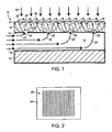
- a cooling apparatus includes an inner structural member 12 that is combined with an outer structural wall 14, forming a plenum therebetween 16.
- the inner structural member 12 and the outer structural wall 14 may be formed from a metallic material, such as, titanium.
- a porous layer 18 may be adhesively bonded or otherwise attached to the outer structural wall 14, and entrance holes 20 may be formed in the outer structural wall 14 and may penetrate the porous layer 18 providing flow of cooling air as indicated by the bold face arrows 22 from the plenum 16 into the porous layer 18.
- the entrance holes 20 may, for example, have a diameter of about 2.29 mm (90 mils), a depth of up to one half the thickness of the porous layer 18, and may be spaced apart by about 6.9 mm (0.27").
- the porous layer 18 may have a void size of less than 50 microns, and may be formed from a ceramic foam insulation.
- the low thermal conductivity of ceramic foam helps minimize the cooling required of the surface temperature control system.
- the low structural strength of ceramic foam compared to conventional porous materials is unimportant since the underlying structural plenum functions as the primary load bearing structure.
- An example of the type of ceramic foam referred to is the commercially available Rescor 360 rigid thermal insulation. This insulation is manufactured by the Cotronics Corporation and may have a density of about 256.3 kg/m 3 (16 lbs./ft. 3 ) and a thickness of about 2.54 cm (1.0").
- the ceramic foam may be bonded to the plenum using commercially available room temperature vulcanizing (RTV) silicone such as GE RTV-630, GE RTV-560, or Dow Corning DC3145. Bondline thickness for the adhesive may be as thin as 0.2 mm (0.008").
- RTV room temperature vulcanizing
- a semi-permeable layer 24 may be disposed on an exterior surface of the porous layer 18.
- the semi-permeable layer 24 protects the underlying low strength porous layer from erosion by high velocity flow and may be composed of a densification layer covered with a ceramic matrix composite (CMC).
- CMC ceramic matrix composite
- An example of a densification product is the commercially available Rescor 901A liquid insulation hardener and rigidizer made by the Cotronics Corporation.
- Nextel 312 fabric combined with a sintered ceramic matrix is an example of a CMC.
- the semi-permeable layer 24 could instead be a highly reflective semi-permeable skin that, when bonded to the exterior surface of the porous layer 18, would both restrict transpiration and minimize absorbed energy.
- the semi-permeable barrier layer may include a plurality of perforations which function as exit holes 26 for the cooling air. These exit holes 26 do not need to be aligned with the entrance holes 20 and may be laid out in staggered rows, forming a uniform grid as depicted in Figure 2 .
- the ratio of exit holes 26 to entrance holes 20 may be about 10.7 exit holes per entrance hole.
- the exit holes 26 may have a diameter of about 1 mm (40 mils), a depth of about 2.5 mm (0.1") and may be spaced 3.05 mm (0.12") apart.
- the exit holes 26 may be formed using a drilling operation or a simple and inexpensive punching operation that penetrates a portion of the semi-permeable layer 24, without the need for an expensive drilling operation.
- a heat source is disposed above the cooling apparatus 10. Cooling air introduced into the plenum 16, as indicated by arrows 32, enters the porous layer 18 through the entrance holes 20, as indicated by arrows 22. The cooling air then spreads in the plane of the porous layer 18 while traveling through the thickness of the porous layer 18, as signified by a plurality of arrows 34 shown in the porous layer 18. The majority of the cooling air flows through the exit holes 26, as indicated by arrows 36, since the semi-permeable layer 24 is a significant hindrance to the flow of cooling air out of the porous layer 18. The small amount of cooling air that does not flow through the exit holes 26 transpires through the semi-permeable layer 24 in the areas between the exit holes 26, as indicated by arrows 28.
- the invention combines the best attributes of film and transpiration cooling while overcoming limitations in each method.
- This system has far fewer holes drilled through the outer wall of the plenum compared to what would be needed in a conventional film cooling system. This makes for a more easily manufactured and structurally stronger plenum.
- a small number of entrance holes in the outer plenum wall maintains even surface temperature control because the cooling air readily diffuses both in-plane and through the thickness of the porous layer, an effect that is amplified by the severe restriction of transpiration that occurs at the semi-permeable layer.
- the coolant exit holes can be thought of as having been moved out from the outer plenum wall to the surface of the porous ceramic foam.
- the exit holes can be easily manufactured in the porous foam by using a simple punch that penetrates the semi-permeable barrier without having to employ an expensive drilling operation.
- the ceramic foam layer additionally serves to greatly reduce the exit velocity of the cooling air. Lower cooling velocities reduce boundary layer penetration, thereby avoiding a common pitfall of conventional film cooling systems and instead providing cooling performance comparable to conventional transpiration cooling systems.
- the low conductivity of the porous ceramic foam insulation minimizes heat transfer from the high heat flux environment and so allows the plenum to be constructed from lower temperature, lower cost materials.
- the low strength of the lightweight ceramic foam insulation is mitigated by bonding the foam directly to the outer structural plenum wall. This arrangement is stronger than systems, utilizing conventional transpiration cooled ceramics, and is lighter than porous sintered metal transpiration cooling systems.
- thermal efficiency of the invention is high because the combination of film cooling and transpiration cooling embodied in this system creates a cooling film at the outer surface with minimal boundary layer penetration. This in turn means that lower coolant flow rates are needed to achieve a given surface temperature when compared to conventional film cooling systems.
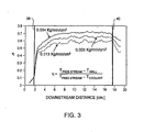
- Cooling effectiveness is a measure of the efficiency with which the cooling air lowers the sample surface temperature below the uncooled surface temperature, as indicated in the equation shown annotated on the plot
- a cooling effectiveness of 0.0 corresponds to a cooled wall temperature equal to the uncooled wall temperature
- a cooling effectiveness of 1.0 corresponds to a cooled wall temperature equal to the plenum supply temperature of the coolant.
- Vertical lines on the plot, 38 and 40 delineate the upstream and downstream limits, respectively, of the exit hole grid on the sample surface.
- the invention achieves a high level of about 7 1 % cooling effectiveness in the fully developed region with a modest 0.034 kg/min/cm 2 (0.49 Ibm/min/in 2 ) cooling air flowrate. Cutting the coolant flowrate over 40% to 0.020 kg/min/cm 2 (0.29 lbm/min/in 2 ) only reduces the fully developed effectiveness to about 65%. A further reduction in flowrate to 0.013 kg/min/cm 2 (0.18 lbm/min/in 2 ) produces a fully developed effectiveness of about 59%. The fact that only 12 percentage points in effectiveness are lost for a nearly two thirds reduction in coolant flowrate highlights the high thermal efficiency of the invention.
- the effectiveness curves also show the high degree of cooling uniformity achieved over the fully developed region of the sample surface, especially at the higher flowrates. This shows that the invention produces a correspondingly high degree of uniformity in surface temperature.
- a cooling system according to the invention is cheaper, structurally stronger, and more thermally efficient than conventional film cooling systems.
- the invention also provides a cooling system that is structurally stronger, lighter in weight, and is at least as thermally efficient as conventional transpiration cooling systems.
- the invention can easily be adapted to a variety of design situations occurring on aircraft, missiles, hypersonic vehicles, and spacecraft.
- An apparatus comprising:
- the porous layer includes a ceramic foam insulation layer.
- the apparatus further including a perforated layer disposed on an exterior surface of the porous layer.
- the perforated layer is made from a semi-permeable material.
- the semi-permeable material is a hardened ceramic matrix composite.
- the outer structural wall is formed from a metallic material.
- a method of cooling a surface comprising:
- a semi-permeable layer is attached to the porous layer.
- the method further including providing a plurality of openings in the semi-permeable layer.
- the pressurized air generally flows through the thickness of the porous layer from the openings in the outer structural wall of the plenum to the semi-permeable layer with some spreading of the flow in the plane of the porous layer.
- the majority of the pressurized air exits the porous layer through the plurality of openings in the semi-permeable layer.
- a portion of the pressurized air transpires through the semi-permeable layer in regions between the openings.
- the pressurized air that exits through the plurality of openings combines with the portion of the pressurized air that transpires through the semi-permeable layer to form a cooling film adjacent to the surface being cooled.
- a method of manufacturing a cooling surface apparatus comprising:
- the porous layer is formed from a ceramic foam insulation material.
- the method further comprising attaching a semi-permeable layer to the exterior surface of the porous layer.
- the method including forming openings in the semi-permeable layer.
- the openings in the semi-permeable layer penetrate a portion of the porous layer.
- the openings are formed in the semi-permeable layer after the semi-permeable layer is attached to the exterior surface of the porous layer.
- An aircraft comprising:
- the porous layer includes a ceramic foam insulation layer.
- the aircraft further including a perforated layer disposed on an exterior surface of the porous layer.
- the perforated layer is made from a semi-permeable material.
- the semi-permeable material is a hardened ceramic matrix composite.
- the outer structural wall is formed from a metallic material.
- a space vehicle comprising:
- the porous layer includes a ceramic foam insulation layer.
- the space vehicle further including a perforated layer disposed on an exterior surface of the porous layer.
- the perforated layer is made from a semi-permeable material.
- the semi-permeable material is a hardened ceramic matrix composite.
- the outer structural wall is formed from a metallic material.
Landscapes
- Engineering & Computer Science (AREA)
- Physics & Mathematics (AREA)
- Aviation & Aerospace Engineering (AREA)
- Mechanical Engineering (AREA)
- Thermal Sciences (AREA)
- Remote Sensing (AREA)
- Chemical & Material Sciences (AREA)
- Health & Medical Sciences (AREA)
- Critical Care (AREA)
- Emergency Medicine (AREA)
- General Health & Medical Sciences (AREA)
- Dispersion Chemistry (AREA)
- General Engineering & Computer Science (AREA)
- Fluid Mechanics (AREA)
- Laminated Bodies (AREA)
- Turbine Rotor Nozzle Sealing (AREA)
- Coating By Spraying Or Casting (AREA)
- Furnace Housings, Linings, Walls, And Ceilings (AREA)
- Control Of Temperature (AREA)
Applications Claiming Priority (3)
| Application Number | Priority Date | Filing Date | Title |
|---|---|---|---|
| US10/455,204 US7055781B2 (en) | 2003-06-05 | 2003-06-05 | Cooled insulation surface temperature control system |
| EP04754014A EP1651518B1 (fr) | 2003-06-05 | 2004-06-01 | Systeme de regulation de la temperature superficielle |
| PCT/US2004/017309 WO2004108531A1 (fr) | 2003-06-05 | 2004-06-01 | Systeme de regulation de la temperature superficielle |
Related Parent Applications (1)
| Application Number | Title | Priority Date | Filing Date |
|---|---|---|---|
| EP04754014A Division EP1651518B1 (fr) | 2003-06-05 | 2004-06-01 | Systeme de regulation de la temperature superficielle |
Publications (3)
| Publication Number | Publication Date |
|---|---|
| EP2108587A2 true EP2108587A2 (fr) | 2009-10-14 |
| EP2108587A3 EP2108587A3 (fr) | 2017-12-13 |
| EP2108587B1 EP2108587B1 (fr) | 2020-10-28 |
Family
ID=33489904
Family Applications (2)
| Application Number | Title | Priority Date | Filing Date |
|---|---|---|---|
| EP09009348.5A Expired - Lifetime EP2108587B1 (fr) | 2003-06-05 | 2004-06-01 | Système de régulation de la temperature d'une surface |
| EP04754014A Expired - Lifetime EP1651518B1 (fr) | 2003-06-05 | 2004-06-01 | Systeme de regulation de la temperature superficielle |
Family Applications After (1)
| Application Number | Title | Priority Date | Filing Date |
|---|---|---|---|
| EP04754014A Expired - Lifetime EP1651518B1 (fr) | 2003-06-05 | 2004-06-01 | Systeme de regulation de la temperature superficielle |
Country Status (9)
| Country | Link |
|---|---|
| US (2) | US7055781B2 (fr) |
| EP (2) | EP2108587B1 (fr) |
| JP (1) | JP4638420B2 (fr) |
| CN (1) | CN100415607C (fr) |
| AT (1) | ATE440029T1 (fr) |
| CA (1) | CA2527105C (fr) |
| DE (1) | DE602004022678D1 (fr) |
| ES (2) | ES2330112T3 (fr) |
| WO (1) | WO2004108531A1 (fr) |
Cited By (1)
| Publication number | Priority date | Publication date | Assignee | Title |
|---|---|---|---|---|
| RU2452669C1 (ru) * | 2010-11-09 | 2012-06-10 | Государственное образовательное учреждение высшего профессионального образования Томский государственный университет (ТГУ) | Способ тепловой защиты головной части летательного аппарата |
Families Citing this family (52)
| Publication number | Priority date | Publication date | Assignee | Title |
|---|---|---|---|---|
| US7055781B2 (en) * | 2003-06-05 | 2006-06-06 | The Boeing Company | Cooled insulation surface temperature control system |
| US7275720B2 (en) * | 2003-06-09 | 2007-10-02 | The Boeing Company | Actively cooled ceramic thermal protection system |
| US20060145020A1 (en) * | 2004-12-10 | 2006-07-06 | Buehler David B | Atmospheric entry thermal protection system |
| US7913928B2 (en) | 2005-11-04 | 2011-03-29 | Alliant Techsystems Inc. | Adaptive structures, systems incorporating same and related methods |
| US7742297B2 (en) * | 2006-04-20 | 2010-06-22 | The Boeing Company | Ceramic foam electronic component cooling |
| US8505616B2 (en) | 2006-04-20 | 2013-08-13 | The Boeing Company | Hybrid ceramic core cold plate |
| US7905275B2 (en) | 2006-04-20 | 2011-03-15 | The Boeing Company | Ceramic foam cold plate |
| US8240361B2 (en) | 2006-11-02 | 2012-08-14 | The Boeing Company | Combined thermal protection and surface temperature control system |
| US8191616B2 (en) * | 2006-11-02 | 2012-06-05 | The Boeing Company | Combined thermal protection and surface temperature control system |
| DE102008057428B4 (de) | 2008-11-07 | 2019-01-31 | Deutsches Zentrum für Luft- und Raumfahrt e.V. | Schutzstruktur und deren Verwendung |
| DE102009015856B4 (de) * | 2009-04-01 | 2012-01-26 | Airbus Operations Gmbh | Rumpfsegment und Verfahren zur Herstellung des Rumpfsegments |
| US8800641B2 (en) * | 2009-06-01 | 2014-08-12 | The Boeing Company | Methods and apparatus for a micro-truss based structural insulation layer |
| US8720828B2 (en) * | 2009-12-03 | 2014-05-13 | The Boeing Company | Extended plug cold plate |
| US10112257B1 (en) * | 2010-07-09 | 2018-10-30 | General Lasertronics Corporation | Coating ablating apparatus with coating removal detection |
| US9633751B2 (en) | 2011-04-01 | 2017-04-25 | The Boeing Company | Liquid lithium first walls for electromagnetic control of plasmas in fusion power reactor environments |
| US9589678B2 (en) | 2011-04-01 | 2017-03-07 | The Boeing Company | Complex shape structure for liquid lithium first walls of fusion power reactor environments |
| US9074829B2 (en) | 2011-12-01 | 2015-07-07 | The Boeing Company | Lightweight high temperature heat exchanger |
| US9182175B2 (en) * | 2011-12-01 | 2015-11-10 | The Boeing Company | Anti-icing heat exchanger |
| US10161691B2 (en) | 2012-01-16 | 2018-12-25 | The Boeing Company | Multi-channel cooling plenum |
| US9895771B2 (en) | 2012-02-28 | 2018-02-20 | General Lasertronics Corporation | Laser ablation for the environmentally beneficial removal of surface coatings |
| RU2509040C2 (ru) * | 2012-03-22 | 2014-03-10 | Федеральное государственное бюджетное учреждение науки Институт химии твердого тела и механохимии Сибирского отделения Российской академии наук (ИХТТМ СО РАН) | Термостойкая система теплозащиты поверхности гиперзвуковых летательных и возвращаемых космических аппаратов |
| US9403600B2 (en) | 2012-05-01 | 2016-08-02 | Lockheed Martin Corporation | Integrated thermal protection and leakage reduction in a supersonic air intake system |
| FR2998262B1 (fr) * | 2012-11-21 | 2016-01-15 | Airbus Operations Sas | Dispositif passif pour generer un film d'air froid en contact avec une surface exterieure d'un aeronef |
| US9493228B2 (en) | 2012-11-28 | 2016-11-15 | The Boeing Company | High heat transfer rate reusable thermal protection system |
| CN103192978B (zh) * | 2013-04-02 | 2015-04-15 | 中国人民解放军国防科学技术大学 | 一种层板式发汗和逆喷组合冷却鼻锥 |
| FR3016413B1 (fr) * | 2014-01-15 | 2018-06-15 | Arianegroup Sas | Systeme de protection thermique pour un reservoir cryogenique d'engin spatial |
| CN103935532B (zh) * | 2014-04-29 | 2016-02-17 | 北京空间飞行器总体设计部 | 一种适用于大角度展开机构的多层帐篷 |
| US10225953B2 (en) | 2014-10-31 | 2019-03-05 | Thermal Corp. | Vehicle thermal management system |
| CN104608942B (zh) * | 2015-02-13 | 2017-05-17 | 中国科学院宁波材料技术与工程研究所 | 一种超高速飞行器的热防护与减阻系统 |
| DE102015111788A1 (de) | 2015-07-21 | 2017-01-26 | Deutsches Zentrum für Luft- und Raumfahrt e.V. | Gleitlagervorrichtung |
| CN106428643A (zh) * | 2016-09-08 | 2017-02-22 | 上海卫星工程研究所 | 削弱外热流装置及其使用方法和空间飞行器 |
| US20180298611A1 (en) * | 2017-04-17 | 2018-10-18 | David R. Hall | Configurable Hydronic Structural Panel |
| CN107298163A (zh) * | 2017-07-05 | 2017-10-27 | 哈尔滨工业大学 | 一种降低高超声速气动热的热防护结构 |
| CN107719630B (zh) * | 2017-09-25 | 2019-08-16 | 中国人民解放军国防科技大学 | 一种层板式燃气发汗鼻锥 |
| CN107891970A (zh) * | 2017-11-10 | 2018-04-10 | 北京卫星环境工程研究所 | 高超声速飞行器气膜冷却用的主动式热防护系统 |
| CN109823508B (zh) * | 2019-02-22 | 2021-07-06 | 西安电子科技大学 | 超限热防护与生存状态感知的高速飞行器柔性蒙皮 |
| US11267551B2 (en) | 2019-11-15 | 2022-03-08 | General Electric Company | System and method for cooling a leading edge of a high speed vehicle |
| US11260953B2 (en) | 2019-11-15 | 2022-03-01 | General Electric Company | System and method for cooling a leading edge of a high speed vehicle |
| US11352120B2 (en) | 2019-11-15 | 2022-06-07 | General Electric Company | System and method for cooling a leading edge of a high speed vehicle |
| US11427330B2 (en) | 2019-11-15 | 2022-08-30 | General Electric Company | System and method for cooling a leading edge of a high speed vehicle |
| US11260976B2 (en) | 2019-11-15 | 2022-03-01 | General Electric Company | System for reducing thermal stresses in a leading edge of a high speed vehicle |
| CN112179218B (zh) * | 2020-09-09 | 2021-10-01 | 西安交通大学 | 基于热解反应的热防护装置 |
| US11745847B2 (en) | 2020-12-08 | 2023-09-05 | General Electric Company | System and method for cooling a leading edge of a high speed vehicle |
| US11407488B2 (en) | 2020-12-14 | 2022-08-09 | General Electric Company | System and method for cooling a leading edge of a high speed vehicle |
| US11577817B2 (en) | 2021-02-11 | 2023-02-14 | General Electric Company | System and method for cooling a leading edge of a high speed vehicle |
| US12110096B2 (en) * | 2021-04-27 | 2024-10-08 | The Boeing Company | Active cooling of windward surface of craft |
| US20230286082A1 (en) * | 2022-03-11 | 2023-09-14 | Ats Industrial Automation Inc. | Laser cleaning of oxidized parts |
| US12673372B2 (en) * | 2022-06-29 | 2026-07-07 | The Boeing Company | Transpirational cooling panel |
| US12498186B2 (en) | 2022-06-29 | 2025-12-16 | The Boeing Company | Transpirational cooling panel |
| US12258118B2 (en) * | 2023-02-08 | 2025-03-25 | The Boeing Company | Thermal protection systems and methods for vehicles moving through a free stream of air |
| CN116750214B (zh) * | 2023-08-18 | 2024-04-16 | 北京临近空间飞行器系统工程研究所 | 一种超高温环境用柔性防热蒙皮 |
| US20260103298A1 (en) * | 2024-10-15 | 2026-04-16 | Textron Systems Corporation | Resisting ablation of vehicle nose tip |
Family Cites Families (44)
| Publication number | Priority date | Publication date | Assignee | Title |
|---|---|---|---|---|
| US2941759A (en) * | 1957-01-14 | 1960-06-21 | Gen Dynamics Corp | Heat exchanger construction |
| US2908455A (en) * | 1957-04-11 | 1959-10-13 | United Aircraft Corp | Surface cooling means for aircraft |
| US3138009A (en) * | 1957-04-17 | 1964-06-23 | Gen Electric | Transpiration cooling system |
| US3267857A (en) * | 1962-04-05 | 1966-08-23 | Jr John E Lindberg | Nose-cone cooling of space vehicles |
| US3261576A (en) * | 1962-06-14 | 1966-07-19 | Olin Mathieson | Aircraft structure |
| CH427118A (de) * | 1963-11-28 | 1966-12-31 | Bbc Brown Boveri & Cie | Verfahren zum Schützen von durch heisse Medien überstrichenen Oberflächenteilen eines hitzebeständigen Körpers |
| US3452553A (en) * | 1967-03-17 | 1969-07-01 | Gen Dynamics Corp | Transpiration cooled window |
| US3614038A (en) * | 1970-01-08 | 1971-10-19 | Ace Filtercraft Inc | Porous metal panel to distribute deicing fluid onto the leading edge of a surface |
| US4151800A (en) * | 1977-04-15 | 1979-05-01 | The United States Of America As Represented By The Administrator Of The National Aeronautics And Space Administration | Thermal insulation protection means |
| US4434201A (en) * | 1981-11-13 | 1984-02-28 | T.K.S. (Aircraft De-Icing) Limited | Porous panel |
| US4849276A (en) * | 1984-02-17 | 1989-07-18 | The Boeing Company | Thermal insulation structure |
| US5000998A (en) * | 1984-02-17 | 1991-03-19 | The Boeing Company | Method for making thermal insulation |
| US5587228A (en) * | 1985-02-05 | 1996-12-24 | The Boeing Company | Microparticle enhanced fibrous ceramics |
| US5041321A (en) * | 1984-11-02 | 1991-08-20 | The Boeing Company | Fiberformed ceramic insulation and method |
| US5310592A (en) * | 1984-11-02 | 1994-05-10 | The Boeing Company | Fibrous ceramic aerobrake |
| US4671348A (en) * | 1985-05-21 | 1987-06-09 | Mcdonnell Douglas Corporation | Transverse flow edge heat pipe |
| US5322725A (en) * | 1988-08-31 | 1994-06-21 | The Boeing Company | Thermal protection system |
| US4991797A (en) * | 1989-01-17 | 1991-02-12 | Northrop Corporation | Infrared signature reduction of aerodynamic surfaces |
| US4990391A (en) * | 1989-02-03 | 1991-02-05 | Rohr Industries, Inc. | Reticulated core to perforate sheet bonding and galvanic barrier |
| DE3914010C2 (de) * | 1989-04-26 | 1995-09-14 | Osaka Fuji Corp | Verfahren zur Herstellung von Metall-Keramik-Verbundwerkstoffen sowie Verwendung des Verfahrens zur Steuerung der Materialeigenschaften von Verbundwerkstoffen |
| US5374476A (en) | 1990-10-22 | 1994-12-20 | Ball Corporation | Thermal insulating system and method |
| US5236151A (en) * | 1991-12-23 | 1993-08-17 | General Electric Company | Thermal barrier structure |
| FR2688191B1 (fr) * | 1992-03-03 | 1994-05-27 | Aerospatiale | Dispositif de protection thermique utilisant la vaporisation et la surchauffe d'un liquide rechargeable. |
| JPH06173772A (ja) * | 1992-08-10 | 1994-06-21 | Boeing Co:The | 逆推進装置内壁およびそのサンドイッチ構造 |
| US5624613A (en) * | 1993-04-01 | 1997-04-29 | The Boeing Company | Rigidized refractory fibrous ceramic insulation |
| US5402965A (en) * | 1993-09-20 | 1995-04-04 | Rockwell International Corporation | Reusable flyback satellite |
| US6074699A (en) * | 1994-04-29 | 2000-06-13 | Mcdonnell Douglas Corporation | Surface hardness of articles by reactive phosphate treatment |
| GB2294709B (en) * | 1994-11-04 | 1998-03-04 | Rolls Royce Plc | A method of manufacturing a porous material |
| FR2752289B1 (fr) | 1996-08-06 | 1998-10-30 | Thomson Csf | Dispositif de refroidissement, notamment de modules electroniques |
| US5980980A (en) * | 1996-10-29 | 1999-11-09 | Mcdonnell Douglas Corporation | Method of repairing porous ceramic bodies and ceramic composition for same |
| US5958583A (en) * | 1996-12-20 | 1999-09-28 | The Boeing Company | Alumina-based protective coating for ceramic materials |
| US6007026A (en) * | 1997-06-30 | 1999-12-28 | The Boeing Company | Quick installation-removal thermal insulation blanket for space craft |
| US6733907B2 (en) * | 1998-03-27 | 2004-05-11 | Siemens Westinghouse Power Corporation | Hybrid ceramic material composed of insulating and structural ceramic layers |
| US6086664A (en) * | 1998-05-12 | 2000-07-11 | The Boeing Company | Efficient, environmentally acceptable method for waterproofing insulation material |
| DE19910779C2 (de) * | 1999-03-11 | 2002-01-24 | Airbus Gmbh | In einer Flugzeugkabine angeordnetes Staufach für Handgepäck |
| US6521555B1 (en) * | 1999-06-16 | 2003-02-18 | First Quality Nonwovens, Inc. | Method of making media of controlled porosity and product thereof |
| US6419189B1 (en) * | 2000-11-01 | 2002-07-16 | The Boeing Company | Hot ruddervator apparatus and method for an aerospacecraft |
| US6613255B2 (en) * | 2001-04-13 | 2003-09-02 | The Boeing Company | Method of making a permeable ceramic tile insulation |
| KR100398058B1 (ko) * | 2001-05-18 | 2003-09-19 | 주식회사 경동도시가스 | 수식된 θ-알루미나에 담지되어 이루어진 니켈계 개질촉매및 이를 이용한 천연가스로부터 합성가스의 제조방법 |
| US20020195525A1 (en) * | 2001-06-21 | 2002-12-26 | Anton Claire E. | Spray on-foam insulation system for an aircraft |
| US6919103B2 (en) | 2001-08-10 | 2005-07-19 | The Boeing Company | Surface protection of porous ceramic bodies |
| US6607851B2 (en) * | 2001-10-26 | 2003-08-19 | The Boeing Company | Multi-layer ceramic fiber insulation tile |
| US6712318B2 (en) * | 2001-11-26 | 2004-03-30 | The Boeing Company | Impact resistant surface insulation tile for a space vehicle and associated protection method |
| US7055781B2 (en) * | 2003-06-05 | 2006-06-06 | The Boeing Company | Cooled insulation surface temperature control system |
-
2003
- 2003-06-05 US US10/455,204 patent/US7055781B2/en not_active Expired - Lifetime
-
2004
- 2004-06-01 CN CNB2004800224473A patent/CN100415607C/zh not_active Expired - Lifetime
- 2004-06-01 DE DE602004022678T patent/DE602004022678D1/de not_active Expired - Lifetime
- 2004-06-01 EP EP09009348.5A patent/EP2108587B1/fr not_active Expired - Lifetime
- 2004-06-01 ES ES04754014T patent/ES2330112T3/es not_active Expired - Lifetime
- 2004-06-01 JP JP2006515078A patent/JP4638420B2/ja not_active Expired - Lifetime
- 2004-06-01 WO PCT/US2004/017309 patent/WO2004108531A1/fr not_active Ceased
- 2004-06-01 CA CA002527105A patent/CA2527105C/fr not_active Expired - Lifetime
- 2004-06-01 ES ES09009348T patent/ES2845349T3/es not_active Expired - Lifetime
- 2004-06-01 EP EP04754014A patent/EP1651518B1/fr not_active Expired - Lifetime
- 2004-06-01 AT AT04754014T patent/ATE440029T1/de not_active IP Right Cessation
-
2005
- 2005-11-10 US US11/271,600 patent/US7232093B2/en not_active Expired - Lifetime
Cited By (1)
| Publication number | Priority date | Publication date | Assignee | Title |
|---|---|---|---|---|
| RU2452669C1 (ru) * | 2010-11-09 | 2012-06-10 | Государственное образовательное учреждение высшего профессионального образования Томский государственный университет (ТГУ) | Способ тепловой защиты головной части летательного аппарата |
Also Published As
| Publication number | Publication date |
|---|---|
| ES2330112T3 (es) | 2009-12-04 |
| JP4638420B2 (ja) | 2011-02-23 |
| ATE440029T1 (de) | 2009-09-15 |
| CN1832883A (zh) | 2006-09-13 |
| EP1651518A1 (fr) | 2006-05-03 |
| CA2527105C (fr) | 2008-12-02 |
| JP2006526540A (ja) | 2006-11-24 |
| EP2108587B1 (fr) | 2020-10-28 |
| US20040245389A1 (en) | 2004-12-09 |
| US7055781B2 (en) | 2006-06-06 |
| CA2527105A1 (fr) | 2004-12-16 |
| DE602004022678D1 (de) | 2009-10-01 |
| US7232093B2 (en) | 2007-06-19 |
| US20060060702A1 (en) | 2006-03-23 |
| CN100415607C (zh) | 2008-09-03 |
| ES2845349T3 (es) | 2021-07-26 |
| EP1651518B1 (fr) | 2009-08-19 |
| WO2004108531A1 (fr) | 2004-12-16 |
| EP2108587A3 (fr) | 2017-12-13 |
Similar Documents
| Publication | Publication Date | Title |
|---|---|---|
| EP1651518B1 (fr) | Systeme de regulation de la temperature superficielle | |
| US7275720B2 (en) | Actively cooled ceramic thermal protection system | |
| EP2077962B1 (fr) | Système de protection thermique et de régulation de température superficielle combinées | |
| CA2757905C (fr) | Procedes et appareil pour une couche d'isolation structurale a base de micro-treillis | |
| US7140426B2 (en) | Radiant panel | |
| US5527588A (en) | Micro heat pipe panels and method for producing same | |
| US3613778A (en) | Flat plate heat pipe with structural wicks | |
| US10107560B2 (en) | Multifunctional thermal management system and related method | |
| JP5254133B2 (ja) | 熱バリアシステム | |
| US6752358B1 (en) | Laminar flow control system and suction panel for use therewith | |
| JP2009002575A (ja) | ハニカムパネル及びその製造方法 | |
| JP5730552B2 (ja) | 延長プラグコールドプレート | |
| JPS62186128A (ja) | ガスタービン用温度感応積層多孔性金属パネル | |
| US20070247808A1 (en) | Ceramic foam electronic component cooling | |
| Wadia | Advanced combustor liner cooling technology for gas turbines | |
| JP7049849B2 (ja) | 冷却装置 | |
| El‐Genk et al. | Performance analysis of potassium heat pipes radiator for HP‐STMCs space reactor power system | |
| US20050183851A1 (en) | High efficiency flat panel microchannel heat exchanger | |
| KR102445888B1 (ko) | 흡음용 천장재 및 그 제조 방법 | |
| Camarda et al. | Micro heat pipe panels and method for producing same |
Legal Events
| Date | Code | Title | Description |
|---|---|---|---|
| PUAI | Public reference made under article 153(3) epc to a published international application that has entered the european phase |
Free format text: ORIGINAL CODE: 0009012 |
|
| 17P | Request for examination filed |
Effective date: 20090717 |
|
| AC | Divisional application: reference to earlier application |
Ref document number: 1651518 Country of ref document: EP Kind code of ref document: P |
|
| AK | Designated contracting states |
Kind code of ref document: A2 Designated state(s): AT BE BG CH CY CZ DE DK EE ES FI FR GB GR HU IE IT LI LU MC NL PL PT RO SE SI SK TR |
|
| PUAL | Search report despatched |
Free format text: ORIGINAL CODE: 0009013 |
|
| AK | Designated contracting states |
Kind code of ref document: A3 Designated state(s): AT BE BG CH CY CZ DE DK EE ES FI FR GB GR HU IE IT LI LU MC NL PL PT RO SE SI SK TR |
|
| RIC1 | Information provided on ipc code assigned before grant |
Ipc: B64G 1/58 20060101AFI20171108BHEP Ipc: B64C 1/38 20060101ALI20171108BHEP |
|
| STAA | Information on the status of an ep patent application or granted ep patent |
Free format text: STATUS: EXAMINATION IS IN PROGRESS |
|
| 17Q | First examination report despatched |
Effective date: 20190220 |
|
| GRAP | Despatch of communication of intention to grant a patent |
Free format text: ORIGINAL CODE: EPIDOSNIGR1 |
|
| STAA | Information on the status of an ep patent application or granted ep patent |
Free format text: STATUS: GRANT OF PATENT IS INTENDED |
|
| INTG | Intention to grant announced |
Effective date: 20200519 |
|
| GRAS | Grant fee paid |
Free format text: ORIGINAL CODE: EPIDOSNIGR3 |
|
| GRAA | (expected) grant |
Free format text: ORIGINAL CODE: 0009210 |
|
| STAA | Information on the status of an ep patent application or granted ep patent |
Free format text: STATUS: THE PATENT HAS BEEN GRANTED |
|
| AC | Divisional application: reference to earlier application |
Ref document number: 1651518 Country of ref document: EP Kind code of ref document: P |
|
| AK | Designated contracting states |
Kind code of ref document: B1 Designated state(s): AT BE BG CH CY CZ DE DK EE ES FI FR GB GR HU IE IT LI LU MC NL PL PT RO SE SI SK TR |
|
| REG | Reference to a national code |
Ref country code: GB Ref legal event code: FG4D |
|
| REG | Reference to a national code |
Ref country code: CH Ref legal event code: EP |
|
| REG | Reference to a national code |
Ref country code: AT Ref legal event code: REF Ref document number: 1327985 Country of ref document: AT Kind code of ref document: T Effective date: 20201115 |
|
| REG | Reference to a national code |
Ref country code: DE Ref legal event code: R096 Ref document number: 602004054848 Country of ref document: DE |
|
| REG | Reference to a national code |
Ref country code: IE Ref legal event code: FG4D |
|
| REG | Reference to a national code |
Ref country code: AT Ref legal event code: MK05 Ref document number: 1327985 Country of ref document: AT Kind code of ref document: T Effective date: 20201028 |
|
| REG | Reference to a national code |
Ref country code: NL Ref legal event code: MP Effective date: 20201028 |
|
| PG25 | Lapsed in a contracting state [announced via postgrant information from national office to epo] |
Ref country code: NL Free format text: LAPSE BECAUSE OF FAILURE TO SUBMIT A TRANSLATION OF THE DESCRIPTION OR TO PAY THE FEE WITHIN THE PRESCRIBED TIME-LIMIT Effective date: 20201028 Ref country code: PT Free format text: LAPSE BECAUSE OF FAILURE TO SUBMIT A TRANSLATION OF THE DESCRIPTION OR TO PAY THE FEE WITHIN THE PRESCRIBED TIME-LIMIT Effective date: 20210301 Ref country code: FI Free format text: LAPSE BECAUSE OF FAILURE TO SUBMIT A TRANSLATION OF THE DESCRIPTION OR TO PAY THE FEE WITHIN THE PRESCRIBED TIME-LIMIT Effective date: 20201028 Ref country code: GR Free format text: LAPSE BECAUSE OF FAILURE TO SUBMIT A TRANSLATION OF THE DESCRIPTION OR TO PAY THE FEE WITHIN THE PRESCRIBED TIME-LIMIT Effective date: 20210129 |
|
| PG25 | Lapsed in a contracting state [announced via postgrant information from national office to epo] |
Ref country code: BG Free format text: LAPSE BECAUSE OF FAILURE TO SUBMIT A TRANSLATION OF THE DESCRIPTION OR TO PAY THE FEE WITHIN THE PRESCRIBED TIME-LIMIT Effective date: 20210128 Ref country code: AT Free format text: LAPSE BECAUSE OF FAILURE TO SUBMIT A TRANSLATION OF THE DESCRIPTION OR TO PAY THE FEE WITHIN THE PRESCRIBED TIME-LIMIT Effective date: 20201028 Ref country code: PL Free format text: LAPSE BECAUSE OF FAILURE TO SUBMIT A TRANSLATION OF THE DESCRIPTION OR TO PAY THE FEE WITHIN THE PRESCRIBED TIME-LIMIT Effective date: 20201028 Ref country code: SE Free format text: LAPSE BECAUSE OF FAILURE TO SUBMIT A TRANSLATION OF THE DESCRIPTION OR TO PAY THE FEE WITHIN THE PRESCRIBED TIME-LIMIT Effective date: 20201028 |
|
| REG | Reference to a national code |
Ref country code: ES Ref legal event code: FG2A Ref document number: 2845349 Country of ref document: ES Kind code of ref document: T3 Effective date: 20210726 |
|
| REG | Reference to a national code |
Ref country code: DE Ref legal event code: R097 Ref document number: 602004054848 Country of ref document: DE |
|
| PG25 | Lapsed in a contracting state [announced via postgrant information from national office to epo] |
Ref country code: CZ Free format text: LAPSE BECAUSE OF FAILURE TO SUBMIT A TRANSLATION OF THE DESCRIPTION OR TO PAY THE FEE WITHIN THE PRESCRIBED TIME-LIMIT Effective date: 20201028 Ref country code: EE Free format text: LAPSE BECAUSE OF FAILURE TO SUBMIT A TRANSLATION OF THE DESCRIPTION OR TO PAY THE FEE WITHIN THE PRESCRIBED TIME-LIMIT Effective date: 20201028 Ref country code: SK Free format text: LAPSE BECAUSE OF FAILURE TO SUBMIT A TRANSLATION OF THE DESCRIPTION OR TO PAY THE FEE WITHIN THE PRESCRIBED TIME-LIMIT Effective date: 20201028 Ref country code: RO Free format text: LAPSE BECAUSE OF FAILURE TO SUBMIT A TRANSLATION OF THE DESCRIPTION OR TO PAY THE FEE WITHIN THE PRESCRIBED TIME-LIMIT Effective date: 20201028 |
|
| PG25 | Lapsed in a contracting state [announced via postgrant information from national office to epo] |
Ref country code: DK Free format text: LAPSE BECAUSE OF FAILURE TO SUBMIT A TRANSLATION OF THE DESCRIPTION OR TO PAY THE FEE WITHIN THE PRESCRIBED TIME-LIMIT Effective date: 20201028 |
|
| PLBE | No opposition filed within time limit |
Free format text: ORIGINAL CODE: 0009261 |
|
| STAA | Information on the status of an ep patent application or granted ep patent |
Free format text: STATUS: NO OPPOSITION FILED WITHIN TIME LIMIT |
|
| 26N | No opposition filed |
Effective date: 20210729 |
|
| PG25 | Lapsed in a contracting state [announced via postgrant information from national office to epo] |
Ref country code: SI Free format text: LAPSE BECAUSE OF FAILURE TO SUBMIT A TRANSLATION OF THE DESCRIPTION OR TO PAY THE FEE WITHIN THE PRESCRIBED TIME-LIMIT Effective date: 20201028 |
|
| PG25 | Lapsed in a contracting state [announced via postgrant information from national office to epo] |
Ref country code: MC Free format text: LAPSE BECAUSE OF FAILURE TO SUBMIT A TRANSLATION OF THE DESCRIPTION OR TO PAY THE FEE WITHIN THE PRESCRIBED TIME-LIMIT Effective date: 20201028 |
|
| REG | Reference to a national code |
Ref country code: CH Ref legal event code: PL |
|
| REG | Reference to a national code |
Ref country code: BE Ref legal event code: MM Effective date: 20210630 |
|
| PG25 | Lapsed in a contracting state [announced via postgrant information from national office to epo] |
Ref country code: LU Free format text: LAPSE BECAUSE OF NON-PAYMENT OF DUE FEES Effective date: 20210601 |
|
| PG25 | Lapsed in a contracting state [announced via postgrant information from national office to epo] |
Ref country code: LI Free format text: LAPSE BECAUSE OF NON-PAYMENT OF DUE FEES Effective date: 20210630 Ref country code: IE Free format text: LAPSE BECAUSE OF NON-PAYMENT OF DUE FEES Effective date: 20210601 Ref country code: CH Free format text: LAPSE BECAUSE OF NON-PAYMENT OF DUE FEES Effective date: 20210630 |
|
| PG25 | Lapsed in a contracting state [announced via postgrant information from national office to epo] |
Ref country code: BE Free format text: LAPSE BECAUSE OF NON-PAYMENT OF DUE FEES Effective date: 20210630 |
|
| PG25 | Lapsed in a contracting state [announced via postgrant information from national office to epo] |
Ref country code: HU Free format text: LAPSE BECAUSE OF FAILURE TO SUBMIT A TRANSLATION OF THE DESCRIPTION OR TO PAY THE FEE WITHIN THE PRESCRIBED TIME-LIMIT; INVALID AB INITIO Effective date: 20040601 Ref country code: CY Free format text: LAPSE BECAUSE OF FAILURE TO SUBMIT A TRANSLATION OF THE DESCRIPTION OR TO PAY THE FEE WITHIN THE PRESCRIBED TIME-LIMIT Effective date: 20201028 |
|
| P01 | Opt-out of the competence of the unified patent court (upc) registered |
Effective date: 20230503 |
|
| PGFP | Annual fee paid to national office [announced via postgrant information from national office to epo] |
Ref country code: FR Payment date: 20230626 Year of fee payment: 20 Ref country code: DE Payment date: 20230626 Year of fee payment: 20 |
|
| PGFP | Annual fee paid to national office [announced via postgrant information from national office to epo] |
Ref country code: IT Payment date: 20230620 Year of fee payment: 20 Ref country code: GB Payment date: 20230627 Year of fee payment: 20 Ref country code: ES Payment date: 20230703 Year of fee payment: 20 |
|
| REG | Reference to a national code |
Ref country code: DE Ref legal event code: R071 Ref document number: 602004054848 Country of ref document: DE |
|
| REG | Reference to a national code |
Ref country code: GB Ref legal event code: PE20 Expiry date: 20240531 Ref country code: ES Ref legal event code: FD2A Effective date: 20240626 |
|
| PG25 | Lapsed in a contracting state [announced via postgrant information from national office to epo] |
Ref country code: TR Free format text: LAPSE BECAUSE OF FAILURE TO SUBMIT A TRANSLATION OF THE DESCRIPTION OR TO PAY THE FEE WITHIN THE PRESCRIBED TIME-LIMIT Effective date: 20201028 |
|
| PG25 | Lapsed in a contracting state [announced via postgrant information from national office to epo] |
Ref country code: GB Free format text: LAPSE BECAUSE OF EXPIRATION OF PROTECTION Effective date: 20240531 |
|
| PG25 | Lapsed in a contracting state [announced via postgrant information from national office to epo] |
Ref country code: ES Free format text: LAPSE BECAUSE OF EXPIRATION OF PROTECTION Effective date: 20240602 |
|
| PG25 | Lapsed in a contracting state [announced via postgrant information from national office to epo] |
Ref country code: GB Free format text: LAPSE BECAUSE OF EXPIRATION OF PROTECTION Effective date: 20240531 Ref country code: ES Free format text: LAPSE BECAUSE OF EXPIRATION OF PROTECTION Effective date: 20240602 |