EP2108736A2 - Procédé de fabrication d'éléments de machines et bandage de cylindre ainsi fabriqué - Google Patents
Procédé de fabrication d'éléments de machines et bandage de cylindre ainsi fabriqué Download PDFInfo
- Publication number
- EP2108736A2 EP2108736A2 EP09155207A EP09155207A EP2108736A2 EP 2108736 A2 EP2108736 A2 EP 2108736A2 EP 09155207 A EP09155207 A EP 09155207A EP 09155207 A EP09155207 A EP 09155207A EP 2108736 A2 EP2108736 A2 EP 2108736A2
- Authority
- EP
- European Patent Office
- Prior art keywords
- passage opening
- machine part
- heating
- tool
- resistance
- Prior art date
- Legal status (The legal status is an assumption and is not a legal conclusion. Google has not performed a legal analysis and makes no representation as to the accuracy of the status listed.)
- Withdrawn
Links
Images


Classifications
-
- D—TEXTILES; PAPER
- D21—PAPER-MAKING; PRODUCTION OF CELLULOSE
- D21F—PAPER-MAKING MACHINES; METHODS OF PRODUCING PAPER THEREON
- D21F3/00—Press section of machines for making continuous webs of paper
- D21F3/02—Wet presses
- D21F3/10—Suction rolls, e.g. couch rolls
-
- C—CHEMISTRY; METALLURGY
- C21—METALLURGY OF IRON
- C21D—MODIFYING THE PHYSICAL STRUCTURE OF FERROUS METALS; GENERAL DEVICES FOR HEAT TREATMENT OF FERROUS OR NON-FERROUS METALS OR ALLOYS; MAKING METAL MALLEABLE, e.g. BY DECARBURISATION OR TEMPERING
- C21D1/00—General methods or devices for heat treatment, e.g. annealing, hardening, quenching or tempering
- C21D1/34—Methods of heating
- C21D1/38—Heating by cathodic discharges
-
- C—CHEMISTRY; METALLURGY
- C21—METALLURGY OF IRON
- C21D—MODIFYING THE PHYSICAL STRUCTURE OF FERROUS METALS; GENERAL DEVICES FOR HEAT TREATMENT OF FERROUS OR NON-FERROUS METALS OR ALLOYS; MAKING METAL MALLEABLE, e.g. BY DECARBURISATION OR TEMPERING
- C21D7/00—Modifying the physical properties of iron or steel by deformation
- C21D7/02—Modifying the physical properties of iron or steel by deformation by cold working
- C21D7/10—Modifying the physical properties of iron or steel by deformation by cold working of the whole cross-section, e.g. of concrete reinforcing bars
- C21D7/12—Modifying the physical properties of iron or steel by deformation by cold working of the whole cross-section, e.g. of concrete reinforcing bars by expanding tubular bodies
-
- C—CHEMISTRY; METALLURGY
- C21—METALLURGY OF IRON
- C21D—MODIFYING THE PHYSICAL STRUCTURE OF FERROUS METALS; GENERAL DEVICES FOR HEAT TREATMENT OF FERROUS OR NON-FERROUS METALS OR ALLOYS; MAKING METAL MALLEABLE, e.g. BY DECARBURISATION OR TEMPERING
- C21D9/00—Heat treatment, e.g. annealing, hardening, quenching or tempering, adapted for particular articles; Furnaces therefor
- C21D9/08—Heat treatment, e.g. annealing, hardening, quenching or tempering, adapted for particular articles; Furnaces therefor for tubular bodies or pipes
-
- C—CHEMISTRY; METALLURGY
- C21—METALLURGY OF IRON
- C21D—MODIFYING THE PHYSICAL STRUCTURE OF FERROUS METALS; GENERAL DEVICES FOR HEAT TREATMENT OF FERROUS OR NON-FERROUS METALS OR ALLOYS; MAKING METAL MALLEABLE, e.g. BY DECARBURISATION OR TEMPERING
- C21D1/00—General methods or devices for heat treatment, e.g. annealing, hardening, quenching or tempering
- C21D1/06—Surface hardening
- C21D1/09—Surface hardening by direct application of electrical or wave energy; by particle radiation
-
- Y—GENERAL TAGGING OF NEW TECHNOLOGICAL DEVELOPMENTS; GENERAL TAGGING OF CROSS-SECTIONAL TECHNOLOGIES SPANNING OVER SEVERAL SECTIONS OF THE IPC; TECHNICAL SUBJECTS COVERED BY FORMER USPC CROSS-REFERENCE ART COLLECTIONS [XRACs] AND DIGESTS
- Y10—TECHNICAL SUBJECTS COVERED BY FORMER USPC
- Y10T—TECHNICAL SUBJECTS COVERED BY FORMER US CLASSIFICATION
- Y10T29/00—Metal working
- Y10T29/49—Method of mechanical manufacture
- Y10T29/49544—Roller making
-
- Y—GENERAL TAGGING OF NEW TECHNOLOGICAL DEVELOPMENTS; GENERAL TAGGING OF CROSS-SECTIONAL TECHNOLOGIES SPANNING OVER SEVERAL SECTIONS OF THE IPC; TECHNICAL SUBJECTS COVERED BY FORMER USPC CROSS-REFERENCE ART COLLECTIONS [XRACs] AND DIGESTS
- Y10—TECHNICAL SUBJECTS COVERED BY FORMER USPC
- Y10T—TECHNICAL SUBJECTS COVERED BY FORMER US CLASSIFICATION
- Y10T428/00—Stock material or miscellaneous articles
- Y10T428/13—Hollow or container type article [e.g., tube, vase, etc.]
Definitions
- the present invention relates to a method for the production of mechanically highly loadable machine parts having at least one passage opening, in particular Saugwalzenmäntel of paper machines.
- the present invention relates to roll shells with at least one passage opening, in particular suction roll shells for paper machines.
- Rollers in the wet area of paper machines are permanently loaded during operation by chemically aggressive media.
- machine parts are protected from corrosion by paints or special coatings. Since the transition of the wellbore surface to the roll shell surfaces is sharp-edged, the adhesion of the coating is just critical there. In addition, the coating in the region of the hole wall with very low surface roughness would be realized in order to avoid clogging of Saugwalzenlöcher.
- suction roll shells are therefore made of special materials in which a passive layer forms on its own due to the material alloy. Under certain conditions, this protective layer renews itself after damage such as scratches, cracks and the like itself.
- each suction roll jacket becomes fatigued. It comes to the so-called Corrosion fatigue.
- Corrosion fatigue With certain types of suction rollers, cracking occurs in the medium term, reducing the service life to a few years. A higher quality alloy can not prevent this cracking, but only causes the cracking or crack growth is slowed down.
- the invention has for its object to provide a method of the type mentioned, with which the cracking can be reduced or prevented in such machine parts.
- This object is achieved in that the material properties of the machine part are limited locally limited in the region of the passage opening in the sense of increasing the resistance to vibration cracking corrosion of the machine part.
- the increase in strength can be done by introducing internal stresses or by structural change.
- the residual stresses can be generated mechanically in particular, the microstructural change thermally.
- a mechanical generation of residual stresses preferably takes place by plastic deformation, a thermal change of the material structure preferably by local heating and rapid cooling.
- a tool such as ball or plunger with a larger diameter than the passage opening is passed through it.
- mechanical pressure is exerted on the wall of the passage opening and the near-surface region thereof, whereby the desired residual stresses can be generated.
- the oversize is preferably between about 0.5 microns and about 15 microns.
- a pressure on the wall of the openings and / or their near-surface areas can also be hydrostatic.
- a hollow mandrel can be introduced into the passage openings and expanded by introducing a pressure medium.
- the method according to the invention can basically be used with different materials, especially with metals.
- the strength of the machine part can be improved by changing the material structure in the region of the passage opening.
- the change in the material structure can be effected in particular by heating and then rapid cooling of the edge region.
- a heating to over 1000 ° C has proven to be suitable.
- the heating can be done inductively or by plasma technology or laser.
- the increased by the heating ferritic portion is stabilized by the rapid cooling.
- an induction coil can be retracted into the passage openings.
- the preferably water-cooled induction coil heats the outermost surface layer of the bore.
- a hollow electrode with radial holes can be retracted into the hole. Protective gas is passed through the radial holes. By applying a voltage between the electrode and the machine part, a plasma is generated, which brings the material on the wall of the passage opening to the desired temperature, which is possible in a few seconds.
- the self-cooling performance is often sufficient due to the heat flow in the material. Otherwise, an additional cooling may be provided, for example a water cooling. Thus, the desired rapid cooling can be ensured.
- Fig. 1 In Fig. 1 is shown how 2 compressive stresses in the region of the bore 1 are generated by introducing a hydrostatic pressure in the bore 1 of a roll shell.
- a hollow mandrel 3 is inserted with clearance in the previously drilled hole 1, as indicated by arrow 4 in Fig. 1a is shown.
- a pressure medium and the internal pressure in the hollow mandrel 3 is increased so that this as in Fig. 1c is widened shown.
- the pressure exerted thereby on the wall 5 of the bore 1 pressure is indicated by arrows 6.
- the pressure medium from the hollow mandrel 3rd Discharged again and the hollow mandrel 3 pulled out after re-deformation of the hole 1.
- the residual compressive stresses produced by this method are in Fig. 2 shown.
- the pressure curve is shown over the hole depth with P 1 .
- the arrows 6 indicate the introduced hydrostatic pressure.
- the applied compressive stresses remain relatively constant over the entire bore depth. This corresponds to the course of the tensile stresses under load of the roll shell and therefore counteract a vibration cracking corrosion in the desired manner.
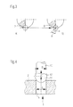
- Fig. 3 shows how can be generated by mechanical processing compressive stresses in a hole 1.
- Fig. 3a shows the machining of an existing hole with a conventional drilling tool.
- Fig. 3b shows a tool 8, which consists of a combination of a drilling tool and a plastic deformation tool and is provided with a negative cutting phase 9 for generating the compressive residual stresses.
- the negative cutting phase preferably has a size of about 0.05 mm to about 0.2 mm.
- FIG. 4 Another variant is in Fig. 4 shown.
- a tappet-like tool 10 is introduced with an expanded, for example, spherical head 11 in the bore 1.
- the diameter D of the head 11 is about 0.5 to about 15 microns larger than the diameter d of the bore 1.
- the input and output is carried out according to double arrow 12th
- Fig. 5 shows the introduction of a high temperature in the wall region of the bore 1 for near-surface change of the structure of the workpiece. This is done, for example, as shown, by means of a hollow electrode 13 which is provided with radial holes 14. According to arrow 15 is in the hollow electrode Inserted protective gas, which flows out of the radial holes 14 according to the arrows 16.
- a plasma is then generated by applying a voltage, which brings the material of the roll shell 2 at the bore wall to the desired temperature, in particular greater than 1000 ° C. The heating takes place only for a few seconds.
- the roll shell 2 is cooled, which can be done by the heat dissipation in the material itself, ie by the self-cooling performance of the material. If this is not sufficient, a separate cooling, such as water cooling can be provided.
- the temperature profile generated by the plasma in the bore is in Fig. 6 shown.
- the temperature T is applied over the bore depth. It is as recognizable in the border areas the largest.
- a structural change in the roll material is produced, whereby the phase relationship between ferritic steel and austenitic steel can be changed so that in the region of the bore and in particular at the bore edges a ferrite content of greater than 70% up to 99.9% is achieved.
- the material properties in the region of the bore ie in the critical zones with respect to the vibration crack corrosion, are determined by the ferrite content.
- the phase components remain unchanged, so that there preserve the advantageous properties of the austenitic phase.
- the rapid cooling of the previously present at elevated temperature state is frozen with high ferrite content. Since this hardening is required by increasing the ferrite content only in the area of the holes and there only in the peripheral areas, the introduction of a relatively small amount of heat is sufficient. Accordingly, the cooling can be accomplished relatively easily.
- an inductive method can be used in which an induction coil is lowered into the well and high temperatures are generated by induction. Furthermore, it is also possible to effect the heating by laser technology.
Landscapes
- Chemical & Material Sciences (AREA)
- Engineering & Computer Science (AREA)
- Organic Chemistry (AREA)
- Mechanical Engineering (AREA)
- Materials Engineering (AREA)
- Metallurgy (AREA)
- Crystallography & Structural Chemistry (AREA)
- Physics & Mathematics (AREA)
- Thermal Sciences (AREA)
- Paper (AREA)
- Heat Treatment Of Articles (AREA)
- Rolls And Other Rotary Bodies (AREA)
- Heat Treatments In General, Especially Conveying And Cooling (AREA)
- Making Paper Articles (AREA)
- Machines For Manufacturing Corrugated Board In Mechanical Paper-Making Processes (AREA)
Applications Claiming Priority (2)
| Application Number | Priority Date | Filing Date | Title |
|---|---|---|---|
| DE102008001052A DE102008001052A1 (de) | 2008-04-08 | 2008-04-08 | Verfahren zur Herstellung von Maschinenteilen und danach hergestellter Walzenmantel |
| DE200810040910 DE102008040910A1 (de) | 2008-07-31 | 2008-07-31 | Verfahren zur Herstellung von Maschinenteilen und danach hergestellter Walzenmantel |
Publications (2)
| Publication Number | Publication Date |
|---|---|
| EP2108736A2 true EP2108736A2 (fr) | 2009-10-14 |
| EP2108736A3 EP2108736A3 (fr) | 2012-12-26 |
Family
ID=40809896
Family Applications (1)
| Application Number | Title | Priority Date | Filing Date |
|---|---|---|---|
| EP09155207A Withdrawn EP2108736A3 (fr) | 2008-04-08 | 2009-03-16 | Procédé de fabrication d'éléments de machines et bandage de cylindre ainsi fabriqué |
Country Status (3)
| Country | Link |
|---|---|
| US (1) | US20090252904A1 (fr) |
| EP (1) | EP2108736A3 (fr) |
| JP (1) | JP2009249807A (fr) |
Families Citing this family (1)
| Publication number | Priority date | Publication date | Assignee | Title |
|---|---|---|---|---|
| JP7673410B2 (ja) * | 2021-01-13 | 2025-05-09 | トヨタ自動車株式会社 | 成形加工方法 |
Family Cites Families (7)
| Publication number | Priority date | Publication date | Assignee | Title |
|---|---|---|---|---|
| US3111455A (en) * | 1961-05-29 | 1963-11-19 | Sandusky Foundry & Machine Com | Suction roll shell and method of making same |
| US3487668A (en) * | 1966-07-12 | 1970-01-06 | Western Electric Co | Shaping and forming articles |
| JP2654975B2 (ja) * | 1988-08-25 | 1997-09-17 | 日本鋼管株式会社 | 耐熱ステンレスロール |
| US6073692A (en) * | 1998-03-27 | 2000-06-13 | Baker Hughes Incorporated | Expanding mandrel inflatable packer |
| JP3508095B2 (ja) * | 1999-06-15 | 2004-03-22 | 株式会社クボタ | 耐熱疲労性・耐腐食疲労性およびドリル加工性等に優れたフェライト−オーステナイト二相ステンレス鋼および製紙用サクションロール胴部材 |
| DE102005017794A1 (de) * | 2005-04-14 | 2006-10-19 | Voith Patent Gmbh | Walze |
| FI20055371A0 (fi) * | 2005-07-01 | 2005-07-01 | Metso Paper Inc | Listaväline materiaalirainakonetta varten |
-
2009
- 2009-03-16 EP EP09155207A patent/EP2108736A3/fr not_active Withdrawn
- 2009-04-07 US US12/419,578 patent/US20090252904A1/en not_active Abandoned
- 2009-04-07 JP JP2009092598A patent/JP2009249807A/ja active Pending
Also Published As
| Publication number | Publication date |
|---|---|
| EP2108736A3 (fr) | 2012-12-26 |
| US20090252904A1 (en) | 2009-10-08 |
| JP2009249807A (ja) | 2009-10-29 |
Similar Documents
| Publication | Publication Date | Title |
|---|---|---|
| EP2435589B1 (fr) | Procédé et dispositif de durcissement de surface d'un élément de construction qui est constitué dans la région de sa surface à durcir d'un composé intermétallique | |
| DE102012204409B3 (de) | Verfahren zur Herstellung eines Wälzlagers und Wälzlager | |
| DE3202788C2 (de) | Zylinderlaufbüchse | |
| DE102011055643A1 (de) | Verfahren und Umformwerkzeug zum Warmumformen und Presshärten von Werkstücken aus Stahlblech, insbesondere verzinkten Werkstücken aus Stahlblech | |
| EP2905455B1 (fr) | Procédé de revêtement d'un alésage et bloc cylindre d'un moteur à combustion interne | |
| EP2943703B1 (fr) | Segment de piston à haute résistance à la fatigue pour moteur à combustion interne et procédé pour le fabriquer | |
| EP3685062B1 (fr) | Procede de fabrication d'un composant de palier et composant de palier | |
| EP2108736A2 (fr) | Procédé de fabrication d'éléments de machines et bandage de cylindre ainsi fabriqué | |
| DE102018108117A1 (de) | Zylinderlaufbuchse für verbrennungsmotor | |
| DE102015201644A1 (de) | Verfahren zum Festwalzen eines metallischen Objekts, insbesondere einer Laufbahn eines Wälzlagers | |
| AT411337B (de) | Giesswalze für das stranggiessen von dünnen metallischen bändern | |
| EP3601629B1 (fr) | Segment de piston comprenant une couche de rodage grenaillée et procédé pour sa fabrication | |
| EP2554293A1 (fr) | Procédé de forgeage de tuyau avec bloc creux moulé | |
| DE102008001052A1 (de) | Verfahren zur Herstellung von Maschinenteilen und danach hergestellter Walzenmantel | |
| DE102008040910A1 (de) | Verfahren zur Herstellung von Maschinenteilen und danach hergestellter Walzenmantel | |
| DE102015001617C5 (de) | Mahlwalze und Verfahren zum Abziehen einer Bandage und Aufschrumpfen einer Bandage auf die Welle der Mahlwalze | |
| DE102009018407A1 (de) | Verfahren zum Herstellen einer gebauten Nockenwelle | |
| EP2573260B1 (fr) | Rouleau et procédé de revêtement de rouleau | |
| DE102013222808B4 (de) | Verfahren zur Steigerung der Zahnfußtragfähigkeit eines Getriebeelementes sowie die Verwendung eines Getriebeelementes für ein Achsgetriebe eines Kraftfahrzeuges | |
| DE102018205697B4 (de) | Bremsscheibe und Verfahren zur Herstellung einer Bremsscheibe | |
| EP1529877B1 (fr) | Rouleau pour le traitement thermique d'une bande | |
| DE102009013773A1 (de) | Verfahren zum Herstellen eines rotationssymmetrischen Bauelements und gemäß dem Verfahren hergestellte Walze oder Rolle | |
| DE102020205499A1 (de) | Elektrische Maschine und Verfahren zu deren Herstellung | |
| DE102017003200A1 (de) | Verfahren zur Herstellung plattierter Rundstäbe | |
| DE102014000461B4 (de) | Innenwerkzeug für die Herstellung nahtloser Stahlrohre |
Legal Events
| Date | Code | Title | Description |
|---|---|---|---|
| PUAI | Public reference made under article 153(3) epc to a published international application that has entered the european phase |
Free format text: ORIGINAL CODE: 0009012 |
|
| AK | Designated contracting states |
Kind code of ref document: A2 Designated state(s): AT BE BG CH CY CZ DE DK EE ES FI FR GB GR HR HU IE IS IT LI LT LU LV MC MK MT NL NO PL PT RO SE SI SK TR |
|
| AX | Request for extension of the european patent |
Extension state: AL BA RS |
|
| PUAL | Search report despatched |
Free format text: ORIGINAL CODE: 0009013 |
|
| AK | Designated contracting states |
Kind code of ref document: A3 Designated state(s): AT BE BG CH CY CZ DE DK EE ES FI FR GB GR HR HU IE IS IT LI LT LU LV MC MK MT NL NO PL PT RO SE SI SK TR |
|
| AX | Request for extension of the european patent |
Extension state: AL BA RS |
|
| RIC1 | Information provided on ipc code assigned before grant |
Ipc: C21D 9/08 20060101ALI20121121BHEP Ipc: C21D 7/12 20060101ALI20121121BHEP Ipc: C21D 1/38 20060101ALI20121121BHEP Ipc: D21F 3/10 20060101AFI20121121BHEP |
|
| 17P | Request for examination filed |
Effective date: 20130626 |
|
| RBV | Designated contracting states (corrected) |
Designated state(s): AT BE BG CH CY CZ DE DK EE ES FI FR GB GR HR HU IE IS IT LI LT LU LV MC MK MT NL NO PL PT RO SE SI SK TR |
|
| AKX | Designation fees paid |
Designated state(s): AT BE BG CH CY CZ DE DK EE ES FI FR GB GR HR HU IE IS IT LI LT LU LV MC MK MT NL NO PL PT RO SE SI SK TR |
|
| STAA | Information on the status of an ep patent application or granted ep patent |
Free format text: STATUS: THE APPLICATION IS DEEMED TO BE WITHDRAWN |
|
| 18D | Application deemed to be withdrawn |
Effective date: 20130627 |