EP2108737B1 - Procédé et dispositif destinés au traitement d'une bande de matière fibreuse - Google Patents
Procédé et dispositif destinés au traitement d'une bande de matière fibreuse Download PDFInfo
- Publication number
- EP2108737B1 EP2108737B1 EP09157405A EP09157405A EP2108737B1 EP 2108737 B1 EP2108737 B1 EP 2108737B1 EP 09157405 A EP09157405 A EP 09157405A EP 09157405 A EP09157405 A EP 09157405A EP 2108737 B1 EP2108737 B1 EP 2108737B1
- Authority
- EP
- European Patent Office
- Prior art keywords
- fibrous material
- material web
- treatment path
- treatment stage
- path section
- Prior art date
- Legal status (The legal status is an assumption and is not a legal conclusion. Google has not performed a legal analysis and makes no representation as to the accuracy of the status listed.)
- Not-in-force
Links
- 238000000034 method Methods 0.000 title claims abstract description 21
- 239000002657 fibrous material Substances 0.000 title claims abstract 21
- 239000000126 substance Substances 0.000 claims abstract description 14
- 239000002184 metal Substances 0.000 claims description 9
- 230000006641 stabilisation Effects 0.000 claims 2
- 239000000835 fiber Substances 0.000 abstract description 7
- 239000003381 stabilizer Substances 0.000 abstract description 5
- 239000000654 additive Substances 0.000 abstract description 4
- 230000000996 additive effect Effects 0.000 abstract 2
- 239000000463 material Substances 0.000 abstract 1
- 239000007789 gas Substances 0.000 description 8
- 238000004519 manufacturing process Methods 0.000 description 6
- 239000011148 porous material Substances 0.000 description 6
- 239000000123 paper Substances 0.000 description 5
- 230000002093 peripheral effect Effects 0.000 description 3
- XLYOFNOQVPJJNP-UHFFFAOYSA-N water Substances O XLYOFNOQVPJJNP-UHFFFAOYSA-N 0.000 description 3
- IJGRMHOSHXDMSA-UHFFFAOYSA-N Atomic nitrogen Chemical compound N#N IJGRMHOSHXDMSA-UHFFFAOYSA-N 0.000 description 2
- CURLTUGMZLYLDI-UHFFFAOYSA-N Carbon dioxide Chemical compound O=C=O CURLTUGMZLYLDI-UHFFFAOYSA-N 0.000 description 2
- 230000008901 benefit Effects 0.000 description 2
- 238000009835 boiling Methods 0.000 description 2
- 238000003490 calendering Methods 0.000 description 2
- 230000000295 complement effect Effects 0.000 description 2
- 230000000694 effects Effects 0.000 description 2
- 238000005259 measurement Methods 0.000 description 2
- 239000004005 microsphere Substances 0.000 description 2
- 239000004033 plastic Substances 0.000 description 2
- 229920003023 plastic Polymers 0.000 description 2
- 239000002994 raw material Substances 0.000 description 2
- 238000011144 upstream manufacturing Methods 0.000 description 2
- 239000004971 Cross linker Substances 0.000 description 1
- 239000004372 Polyvinyl alcohol Substances 0.000 description 1
- 229910000831 Steel Inorganic materials 0.000 description 1
- 239000002253 acid Substances 0.000 description 1
- QVGXLLKOCUKJST-UHFFFAOYSA-N atomic oxygen Chemical compound [O] QVGXLLKOCUKJST-UHFFFAOYSA-N 0.000 description 1
- KGBXLFKZBHKPEV-UHFFFAOYSA-N boric acid Chemical compound OB(O)O KGBXLFKZBHKPEV-UHFFFAOYSA-N 0.000 description 1
- 239000001569 carbon dioxide Substances 0.000 description 1
- 229910002092 carbon dioxide Inorganic materials 0.000 description 1
- 239000011111 cardboard Substances 0.000 description 1
- 230000006835 compression Effects 0.000 description 1
- 238000007906 compression Methods 0.000 description 1
- 238000001816 cooling Methods 0.000 description 1
- 230000007423 decrease Effects 0.000 description 1
- 238000000280 densification Methods 0.000 description 1
- 230000005684 electric field Effects 0.000 description 1
- 238000001704 evaporation Methods 0.000 description 1
- 230000008020 evaporation Effects 0.000 description 1
- 238000009499 grossing Methods 0.000 description 1
- 239000002932 luster Substances 0.000 description 1
- 239000003094 microcapsule Substances 0.000 description 1
- 239000000203 mixture Substances 0.000 description 1
- 229910052757 nitrogen Inorganic materials 0.000 description 1
- 239000001301 oxygen Substances 0.000 description 1
- 229910052760 oxygen Inorganic materials 0.000 description 1
- 239000011087 paperboard Substances 0.000 description 1
- 239000002985 plastic film Substances 0.000 description 1
- 229920006255 plastic film Polymers 0.000 description 1
- 229920000642 polymer Polymers 0.000 description 1
- 229920002451 polyvinyl alcohol Polymers 0.000 description 1
- 230000008092 positive effect Effects 0.000 description 1
- 238000002360 preparation method Methods 0.000 description 1
- 230000000717 retained effect Effects 0.000 description 1
- 239000010959 steel Substances 0.000 description 1
- 239000000725 suspension Substances 0.000 description 1
- 238000005979 thermal decomposition reaction Methods 0.000 description 1
- 238000002604 ultrasonography Methods 0.000 description 1
- 238000004804 winding Methods 0.000 description 1
Images
Classifications
-
- D—TEXTILES; PAPER
- D21—PAPER-MAKING; PRODUCTION OF CELLULOSE
- D21G—CALENDERS; ACCESSORIES FOR PAPER-MAKING MACHINES
- D21G1/00—Calenders; Smoothing apparatus
- D21G1/006—Calenders; Smoothing apparatus with extended nips
Definitions
- the invention relates to a method for treating a moving fibrous web, in which the fibrous web is guided over a treatment path between a first and a second follower bearing surface, wherein the fibrous web is clamped in a first treatment section between the contact surfaces.
- the invention further relates to a device for treating a moving fibrous web in a treatment path between a first and a second running contact surface.
- nip length is to be greater than that of a conventional roll nip
- at least one-sided circumferential bands and here preferably metal bands are used.
- a so-called Metallbandkalander is described.
- the smooth metal strip which presses the fibrous web, in particular a paper or board web, against a likewise very smooth roller, the fibrous web is smoothed and compacted only relatively little because of the long treatment route and the low load. This is very advantageous for the paper or board manufacturer because it requires less raw material for the same web length.
- the EP 0 370 185 A discloses a method and apparatus according to the preamble of claim 1.
- the object is achieved in that in a second treatment section section within the treatment section, the contact surfaces to a predetermined distance, which is greater than the fibrous web thickness in the first treatment section section, apart.
- the fibrous web is assigned a precisely defined space in which it can expand. It is envisaged that in the direction of the pulp, this defined distance is maintained so long that the fibrous web has sufficient opportunity and time to extend to the "new limits".
- the contact surfaces in the second treatment path section run parallel to the predetermined distance.
- the fibrous web in the second treatment stretch section is not influenced during its expansion by changing free space cross sections with a larger and smaller passage height.
- the first abutment surface is formed by the surface of a band.
- a tape you have such a flexible component available that a change in the distance of the surface of the tape can be achieved by a simple deformation or curvature in the direction.
- first contact surface is forcibly guided at least in the second treatment section by means of guide elements. Forced operation ensures that the expansion area does not change.
- the predetermined distance of the second treatment route section is adjusted via the guide elements.
- the guide elements can be arranged to be fixable, for example, in other guides.
- a band distributed over the entire width gripping elements which briefly enter into a positive connection with the guide elements.
- the precision with which the distance between the contact surfaces must be adjusted requires that any vibration of the belt can be excluded.
- the distance accuracy may vary no more than +/- 3 ⁇ m across the width to "blow up" the fibrous web in the second treatment section to an acceptable thickness uniformity. Often during a subsequent calendering the distance accuracy should not be significantly worse. Characterized in that in essential areas a positive connection between the band and the guide element is present, this required accuracy in the treatment is secured.
- expansion aids are used which ensure that the fibrous web expands in the second treatment section.
- the fibrous web in the first treatment section in the thickness direction is not so resiliently biased that it expands in the second treatment section section by itself to the defined contact surface distance. Therefore, an expansion aid is provided, which is here supporting.
- a negative pressure above or below the fibrous web and / or an overpressure within the fibrous web triggering chemical is used as an expansion aid.
- a negative pressure above and below the fibrous web can be achieved, for example, if the contact surfaces whose distance is increased to a defined extent in the second treatment section, are completely impermeable to gas.
- the pressure above and below the fibrous web is less by the enlargement of the space between the limiting contact surfaces than in the interior of the fibrous web, so that the fibrous web expands in the thickness direction. This is possibly supported in a very advantageous manner by evaporation of the fibrous web, because by the generation of the negative pressure and the boiling point of the water in the fibers decreases.
- Another advantage is achieved when stabilizing agents are used which ensure that the fibrous web does not collapse after the second treatment path section into its original thickness which is present in the first treatment path section. Due to the elasticity of a fibrous web, there would otherwise be the risk that the web would "spring back” upon exiting the treatment and regain its thickness, which it had already had when entering the second treatment section. And since the web in the first treatment section is usually densified to increase smoothness, the fibrous web would have lost thickness during the overall treatment.
- the object of the invention is achieved in that a first and a second treatment section section is provided and in the second treatment section section guide elements for at least one contact surface are present, which change the distance of the contact surfaces to a predetermined value, which is greater than the fiber web thickness in the first treatment sections section.
- the contact surface distance is increased by guide elements to a predetermined value, then it is ensured that the fibrous web can assume a value set for a defined expansion.
- the surface of a belt is used for at least one contact surface. Thanks to its high flexibility and formability, this surface is particularly easy to adapt to the change in distance.
- the second contact surface may alternatively be formed by a rotating roller surface or a second band.
- At least one band is a metal band.
- a metal strip is particularly smooth sandable and therefore achieves a particularly large effect in the smoothness of the fibrous web.
- At least one band is permeable to gas.
- air is drawn from the environment into the paper web during expansion due to the resulting negative pressure. Pores are formed in the fibrous web or pores are enlarged. After a possible increase in viscosity and the exit from the treatment device, the paper web contains a higher proportion of gas at a higher thickness and thus the desired increase in volume.
- the band distributed over the entire width gripping elements that can briefly enter into a form-fitting bond with the guide elements.
- the gripping elements that are on the not facing the fibrous web side provide the band in this way a precise, vibration-free and possibly adjustable path.
- the guide elements have a magnetic guide.
- the metal strip can rest, for example, on a magnetic roller or another magnetic guide element, in the latter case, a circumferential support belt between the belt and the magnetic guide element should be arranged to avoid mechanical wear.
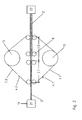
- Fig. 1 shows the treatment device 1 according to the invention a fibrous web 2.
- the fibrous web 2 preferably with a dry content between 20% and 70%, is in a Treatment section 3, which is composed of a first and a second treatment section section 3.1, 3.2, treated.
- a Treatment section 3 which is composed of a first and a second treatment section section 3.1, 3.2, treated.
- it is endeavored to smooth the fibrous web or provide it with luster.
- no volume is to be lost according to the invention.
- Smoothing processes usually take place under pressure between two smooth contact surfaces. These are also present in the treatment device according to the invention.
- the first contact surface bears the designation 4.1 and the second contact surface is labeled 4.2.
- the second surface 4.2 formed by the surface of a roller 6, which is preferably heated from the inside or the outside in a manner not shown, but generally known.
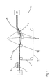
- the second surface 4.2 is formed by that of a belt 7.2, which, in order to be particularly smooth executable, for example, is formed from a steel strip. But there are also plastic bands conceivable.
- the first contact surface 4.1 in both examples the surface of a rotating belt 7.1 is also used.
- the fibrous web 2 between a contact portion of the belt 7.1 and according to Fig. 1 a peripheral portion of the roller 6 or according to Fig.
- the fibrous web 2 undergoes a pressure, it is preferably compacted and smoothed with the application of heat.
- the contact surfaces 4.1 and 4.2 at a predetermined distance 5 (see here Fig. 1 ) apart, which is greater than the thickness of the fibrous web in the first treatment section section. Due to the resulting negative pressure above and below the fibrous web when passing from the first to the second treatment section, this is forcibly expanded. This is the result that the papermaker wishes, because at high densification, the amount of raw material is greater.
- the fibrous web Even in the second treatment section 3.2 section on the smooth contact surfaces 4.1, 4.2 and there is no loss of the achieved smoothness increase more.
- the distance of the contact surfaces 4.1 and 4.2 in the second treatment section depending on the pulp, so for example paper or cardboard, between 3 and 100 microns should be greater than the web thickness in the first treatment section 3.1. For example, a targeted increase would be over 10%.
- auxiliaries are added to the process which accelerate and / or stabilize the desired expansion of the fibrous web 2 in the second treatment section 3.2.
- the addition station 19 is shown, via which the fibrous web 2 a substance is supplied which has the desired properties. This can already be simply water, for example. Because penetrated into the fibrous web, warm water boiling under the negative pressure conditions in the second treatment section section 3.2 and swells up the fibrous web. In general, however, it is about chemical additives, which are also very far before in the manufacturing process, so for example in the Stock preparation of the fibrous web are admixed.
- the belt 7.1, 7.2 for example, be heated inductively. After cooling, the pores in the fibrous web 2 are retained.
- gas-forming substances are introduced into the fibrous web, which expand the fibrous web 2. This expansion can be initiated, for example, when the ambient conditions change. Here are temperature, pressure or pH changes, or the influence of magnetic fields or electric fields conceivable.
- the addition of an acid in the presence of CaCO 3 also serves a similar purpose.
- chemicals are added to the fibrous web which release nitrogen, oxygen or carbon dioxide during their thermal decomposition.
- At least one band 7.1, 7.2 may also be permeable or semipermeable to gases.
- a negative pressure is generated. This then causes air to be sucked through the belt into the space between the abutment surfaces 4.1 and 4.2. This penetrates into the fibrous web 2 and can be formed in internal pores, which in turn leads to the desired volume increase.
- the adhesion forces of the fibrous web 2 on the contact surfaces 4.1 and 4.2 can bring about a positive effect here.
- aids again in the form of supplied chemicals 19, provide an increase in the viscosity of the fibrous web and thus serve as a stabilizing agent. These can restore the viscoelastic effect of the web, after expansion back into a thinner state to reduce significantly.
- examples include polymers such as polyvinyl alcohol connected with a crosslinker such as boric acid (H 3 BO 3 ) called.
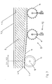
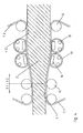
- Fig. 3 and Fig. 4 illustrate two ways to perform at least one band exactly in and at the increased distance.
- the belt 7.2 is provided with a toothing 14 on its side not facing the fibrous web 2.
- the toothing is formed by angled teeth which are arranged in strips over the entire circumference of the belt 7.2.
- corresponding grooves 13 are provided in the areas where the belt has a toothing 7.2, so that the guide means and toothing 14 can not damage each other.
- the guide elements 8 have been formed into gripping elements 9.
- These gripping elements 9 may be guide rollers which have a toothing 14 complementary teeth 15 on the peripheral surface. Grasp the teeth 14, 15 into each other, so the belt is precisely guided 7.1.
- the suspension is arranged adjustable.
- Such an adjustment device 10 is exemplified by an adjustable telescopic tube.
- the distance settings of the belt 7.1 with its first contact surface 4.1 of the second contact surface 4.2 can also be done by motor and then done on the basis of distance measurements or thickness measurements on the fibrous web 2.
- the band is performed 7.2.
- the band 7.2 can be magnetized as a metal band.
- electromagnets 16 form a kind of guide rail for the band 7.2, to which they exert a magnetic force.
- a circumferential sliding belt 17 which rotates between the fibrous web 2 and the electromagnet 16 via sliding band deflection elements 18.
- the sliding band 17, which is preferably made of plastic, outside has a high coefficient of friction to be taken from the fibrous web 2, and inside a very low coefficient of friction to exclude wear on the electromagnet 16 as well as possible. If necessary, this sliding band 17 is also easily replaceable.
- the sliding belt 17 receives a constant distance between the belt 7.2 and electromagnet 16.
- alternating magnetic field either by AC or by alternating acted upon with direct current plus and minus poles eddy currents can be induced in the metal strip 7.2 and thus provided for a heat input.
Landscapes
- Treatment Of Fiber Materials (AREA)
- Preliminary Treatment Of Fibers (AREA)
- Advancing Webs (AREA)
Claims (17)
- Procédé pour le traitement d'une bande de matière fibreuse en mouvement (2), dans lequel on conduit la bande de matière fibreuse (2) sur une section de traitement (3) entre une première et une deuxième faces d'appui (4.1, 4.2) qui l'accompagnent, dans lequel on serre la bande de matière fibreuse (2) entre les faces d'appui (4.1, 4.2) dans une première partie (3.1) de la section de traitement, caractérisé en ce que, dans une deuxième partie (3.2) de la section de traitement, on écarte les faces d'appui (4.1, 4.2) l'une de l'autre à l'intérieur de la section de traitement (3) à une distance prédéterminée (5), qui est plus grande que l'épaisseur de la bande de matière fibreuse dans la première partie (3.1) de la section de traitement.
- Procédé selon la revendication 1, caractérisé en ce que les faces d'appui (4.1, 4.2) sont parallèles, à la distance prédéterminée (5), dans la deuxième partie (3.2) de la section de traitement.
- Procédé selon la revendication 1 ou 2, caractérisé en ce que la première face d'appui (4.1) est formée par la surface d'une bande (7.1).
- Procédé selon l'une quelconque des revendications 1 à 3, caractérisé en ce que la première face d'appui (4.1) est guidée de façon forcée au moyen d'éléments de guidage (8) au moins dans la deuxième partie (3.2) de la section de traitement.
- Procédé selon l'une quelconque des revendications 1 à 4, caractérisé en ce que l'on règle la distance prédéterminée (5) de la deuxième partie (3.2) de la section de traitement au moyen des éléments de guidage (8).
- Procédé selon l'une quelconque des revendications 3 à 5, caractérisé en ce qu'une bande (7.1, 7.2) présente des éléments de prise (9) répartis sur toute la largeur, qui forment brièvement un assemblage par emboîtement avec les éléments de guidage (8).
- Procédé selon l'une quelconque des revendications 1 à 6, caractérisé en ce que l'on utilise des accessoires d'expansion, qui assurent que la bande de matière fibreuse (2) se dilate dans la deuxième partie (3.2) de la section de traitement.
- Procédé selon la revendication 7, caractérisé en ce que l'on utilise comme accessoires d'expansion une dépression au-dessus ou en dessous de la bande de matière fibreuse (2) et/ou un produit chimique produisant une surpression à l'intérieur de la bande de matière fibreuse (2).
- Procédé selon la revendication 7 ou 8, caractérisé en ce que l'on utilise des moyens de stabilisation, qui assurent que la bande de matière fibreuse (2) ne revienne pas, après la deuxième partie (3.2) de la section de traitement, à son épaisseur initiale qui existait dans la première partie (3.1) de la section de traitement.
- Procédé selon la revendication 9, caractérisé en ce que l'on utilise comme moyens de stabilisation des produits chimiques qui augmentent la viscosité de la bande de matière fibreuse (2) et/ou sa teneur en gaz.
- Dispositif pour le traitement d'une bande de matière fibreuse en mouvement (2) dans une section de traitement (3) entre une première et une deuxième faces d'appui (4.1, 4.2) qui l'accompagnent, caractérisé en ce qu'il est prévu une première et une deuxième parties (3.1, 3.2) de la section de traitement et il se trouve dans la deuxième partie (3.2) de la section de traitement des éléments de guidage (8) pour au moins une face d'appui (4.1, 4.2), qui font varier la distance (5) des faces d'appui (4.1, 4.2) à une valeur prédéterminée, qui est plus grande que l'épaisseur de la bande de matière fibreuse dans la première partie (3.1) de la section de traitement.
- Dispositif selon la revendication 11, caractérisé en ce que la première face d'appui (4.1) est formée par la surface d'une bande sans fin (7.1) et la deuxième face d'appui (4.2) est formée par une surface de rouleau.
- Dispositif selon la revendication 11, caractérisé en ce que les deux faces d'appui (4.1, 4.2) sont formées par des surfaces de bandes (7.1, 7.2).
- Dispositif selon l'une quelconque des revendications 11 à 13, caractérisé en ce qu'au moins une bande (7.1, 7.2) est une bande métallique.
- Dispositif selon l'une quelconque des revendications 11 à 14, caractérisé en ce qu'au moins une bande (7.1, 7.2) est perméable au gaz.
- Dispositif selon l'une quelconque des revendications 11 à 15, caractérisé en ce qu'une bande (7.1, 7.2) présente des éléments de prise (9) répartis sur toute la largeur, qui forment brièvement un assemblage par emboîtement avec les éléments de guidage (8).
- Dispositif selon l'une quelconque des revendications 11 à 15, caractérisé en ce que les éléments de guidage (8) présentent un guidage magnétique (16).
Applications Claiming Priority (1)
| Application Number | Priority Date | Filing Date | Title |
|---|---|---|---|
| DE102008001023A DE102008001023A1 (de) | 2008-04-07 | 2008-04-07 | Verfahren und Vorrichtung zur Behandlung einer Faserstoffbahn |
Publications (2)
| Publication Number | Publication Date |
|---|---|
| EP2108737A1 EP2108737A1 (fr) | 2009-10-14 |
| EP2108737B1 true EP2108737B1 (fr) | 2010-10-20 |
Family
ID=40679550
Family Applications (1)
| Application Number | Title | Priority Date | Filing Date |
|---|---|---|---|
| EP09157405A Not-in-force EP2108737B1 (fr) | 2008-04-07 | 2009-04-06 | Procédé et dispositif destinés au traitement d'une bande de matière fibreuse |
Country Status (3)
| Country | Link |
|---|---|
| EP (1) | EP2108737B1 (fr) |
| AT (1) | ATE485422T1 (fr) |
| DE (2) | DE102008001023A1 (fr) |
Family Cites Families (3)
| Publication number | Priority date | Publication date | Assignee | Title |
|---|---|---|---|---|
| DE3920204A1 (de) * | 1988-10-31 | 1990-05-10 | Escher Wyss Gmbh | Verfahren zum glaetten einer papier- oder kartonbahn |
| FI102304B1 (fi) | 1997-04-02 | 1998-11-13 | Valmet Corp | Kalanterointimenetelmä ja menetelmää soveltava kalanteri |
| EP1470289B1 (fr) | 2002-01-29 | 2011-07-13 | Metso Paper, Inc. | Calandre pour traiter une nappe fibreuse enduite ou non enduite |
-
2008
- 2008-04-07 DE DE102008001023A patent/DE102008001023A1/de not_active Withdrawn
-
2009
- 2009-04-06 DE DE502009000133T patent/DE502009000133D1/de active Active
- 2009-04-06 EP EP09157405A patent/EP2108737B1/fr not_active Not-in-force
- 2009-04-06 AT AT09157405T patent/ATE485422T1/de active
Also Published As
| Publication number | Publication date |
|---|---|
| DE102008001023A1 (de) | 2009-10-08 |
| DE502009000133D1 (de) | 2010-12-02 |
| EP2108737A1 (fr) | 2009-10-14 |
| ATE485422T1 (de) | 2010-11-15 |
Similar Documents
| Publication | Publication Date | Title |
|---|---|---|
| DE3705241C2 (fr) | ||
| DE2405222C2 (de) | Verfahren und Vorrichtung zum Herstellen eines magnetischen Aufzeichnungsbandes | |
| DE2753201A1 (de) | Verfahren fuer die behandlung einer papierbahn in der nasspartie einer papiermaschine | |
| DE202013011389U1 (de) | Herstelllinie für das Herstellen von Faserbahnen | |
| DE1436874A1 (de) | Verfahren zum Herstellen dehnungsfaehigen Papiers | |
| DE102007024581A1 (de) | Kalander und Verfahren zur Satinage von Papier- oder Kartonbahnen | |
| EP2079861B1 (fr) | Procédé et dispositif de traitement d'un câble de fibres | |
| EP2108737B1 (fr) | Procédé et dispositif destinés au traitement d'une bande de matière fibreuse | |
| DE10195949B4 (de) | Superkalander und Kalanderaufbau | |
| EP1336686B2 (fr) | Aménagement de calandre à pinçage prolongé et procédé de satinage d'une bande de papier ou de carton | |
| EP4347949B1 (fr) | Procédé et dispositif | |
| EP2295632A1 (fr) | Calendre | |
| EP1382742A2 (fr) | Dispositif et Procédé pour l' imprégnation d' une bande de papier ou carton | |
| DE10206256B4 (de) | Flächenkalandar und Flächenkalandrierverfahren | |
| DE102011089543A1 (de) | Vorrichtung zur Kühlung von bewegtem Flachmaterial | |
| DE102009047462B4 (de) | Verfahren und Vorrichtung zum Streichen einer sich bewegenden Papier- oder Kartonbahn in einer Streichmaschine | |
| DE202011110527U1 (de) | Vorrichtung zur Kühlung von bewegtem Flachmaterial | |
| DE102016201828B4 (de) | Vorrichtung und Verfahren zur Behandlung einer Faserstoffbahn | |
| DE102007055734A1 (de) | Bahnbehandlungsvorrichtung | |
| DE1062538B (de) | Verfahren zur Herstellung von Papier mit grosser Dehnung auf Papiermaschinen | |
| DE102019100884A1 (de) | Vorrichtung und Verfahren zur Behandlung einer Faserstoffbahn | |
| DE102015015949A1 (de) | Verfahren und Vorrichtung zum Behandeln eines Pressfilzes | |
| DE10223774A1 (de) | Folienstreckanlage | |
| DE202023101328U1 (de) | Vorrichtung und Maschine | |
| AT527977A1 (de) | Trockenpartie-Abschnitt zur Herstellung von Kraftpapier |
Legal Events
| Date | Code | Title | Description |
|---|---|---|---|
| PUAI | Public reference made under article 153(3) epc to a published international application that has entered the european phase |
Free format text: ORIGINAL CODE: 0009012 |
|
| AK | Designated contracting states |
Kind code of ref document: A1 Designated state(s): AT BE BG CH CY CZ DE DK EE ES FI FR GB GR HR HU IE IS IT LI LT LU LV MC MK MT NL NO PL PT RO SE SI SK TR |
|
| 17P | Request for examination filed |
Effective date: 20100414 |
|
| GRAP | Despatch of communication of intention to grant a patent |
Free format text: ORIGINAL CODE: EPIDOSNIGR1 |
|
| GRAS | Grant fee paid |
Free format text: ORIGINAL CODE: EPIDOSNIGR3 |
|
| GRAA | (expected) grant |
Free format text: ORIGINAL CODE: 0009210 |
|
| AK | Designated contracting states |
Kind code of ref document: B1 Designated state(s): AT BE BG CH CY CZ DE DK EE ES FI FR GB GR HR HU IE IS IT LI LT LU LV MC MK MT NL NO PL PT RO SE SI SK TR |
|
| REG | Reference to a national code |
Ref country code: GB Ref legal event code: FG4D Free format text: NOT ENGLISH |
|
| REG | Reference to a national code |
Ref country code: CH Ref legal event code: EP |
|
| REG | Reference to a national code |
Ref country code: IE Ref legal event code: FG4D Free format text: LANGUAGE OF EP DOCUMENT: GERMAN |
|
| REF | Corresponds to: |
Ref document number: 502009000133 Country of ref document: DE Date of ref document: 20101202 Kind code of ref document: P |
|
| REG | Reference to a national code |
Ref country code: SE Ref legal event code: TRGR |
|
| REG | Reference to a national code |
Ref country code: NL Ref legal event code: VDEP Effective date: 20101020 |
|
| LTIE | Lt: invalidation of european patent or patent extension |
Effective date: 20101020 |
|
| PG25 | Lapsed in a contracting state [announced via postgrant information from national office to epo] |
Ref country code: NO Free format text: LAPSE BECAUSE OF FAILURE TO SUBMIT A TRANSLATION OF THE DESCRIPTION OR TO PAY THE FEE WITHIN THE PRESCRIBED TIME-LIMIT Effective date: 20110120 Ref country code: LT Free format text: LAPSE BECAUSE OF FAILURE TO SUBMIT A TRANSLATION OF THE DESCRIPTION OR TO PAY THE FEE WITHIN THE PRESCRIBED TIME-LIMIT Effective date: 20101020 |
|
| REG | Reference to a national code |
Ref country code: IE Ref legal event code: FD4D |
|
| PG25 | Lapsed in a contracting state [announced via postgrant information from national office to epo] |
Ref country code: NL Free format text: LAPSE BECAUSE OF FAILURE TO SUBMIT A TRANSLATION OF THE DESCRIPTION OR TO PAY THE FEE WITHIN THE PRESCRIBED TIME-LIMIT Effective date: 20101020 Ref country code: SI Free format text: LAPSE BECAUSE OF FAILURE TO SUBMIT A TRANSLATION OF THE DESCRIPTION OR TO PAY THE FEE WITHIN THE PRESCRIBED TIME-LIMIT Effective date: 20101020 Ref country code: HR Free format text: LAPSE BECAUSE OF FAILURE TO SUBMIT A TRANSLATION OF THE DESCRIPTION OR TO PAY THE FEE WITHIN THE PRESCRIBED TIME-LIMIT Effective date: 20101020 Ref country code: BG Free format text: LAPSE BECAUSE OF FAILURE TO SUBMIT A TRANSLATION OF THE DESCRIPTION OR TO PAY THE FEE WITHIN THE PRESCRIBED TIME-LIMIT Effective date: 20110120 Ref country code: PT Free format text: LAPSE BECAUSE OF FAILURE TO SUBMIT A TRANSLATION OF THE DESCRIPTION OR TO PAY THE FEE WITHIN THE PRESCRIBED TIME-LIMIT Effective date: 20110221 Ref country code: IS Free format text: LAPSE BECAUSE OF FAILURE TO SUBMIT A TRANSLATION OF THE DESCRIPTION OR TO PAY THE FEE WITHIN THE PRESCRIBED TIME-LIMIT Effective date: 20110220 Ref country code: LV Free format text: LAPSE BECAUSE OF FAILURE TO SUBMIT A TRANSLATION OF THE DESCRIPTION OR TO PAY THE FEE WITHIN THE PRESCRIBED TIME-LIMIT Effective date: 20101020 |
|
| PG25 | Lapsed in a contracting state [announced via postgrant information from national office to epo] |
Ref country code: GR Free format text: LAPSE BECAUSE OF FAILURE TO SUBMIT A TRANSLATION OF THE DESCRIPTION OR TO PAY THE FEE WITHIN THE PRESCRIBED TIME-LIMIT Effective date: 20110121 |
|
| PG25 | Lapsed in a contracting state [announced via postgrant information from national office to epo] |
Ref country code: CZ Free format text: LAPSE BECAUSE OF FAILURE TO SUBMIT A TRANSLATION OF THE DESCRIPTION OR TO PAY THE FEE WITHIN THE PRESCRIBED TIME-LIMIT Effective date: 20101020 Ref country code: IE Free format text: LAPSE BECAUSE OF FAILURE TO SUBMIT A TRANSLATION OF THE DESCRIPTION OR TO PAY THE FEE WITHIN THE PRESCRIBED TIME-LIMIT Effective date: 20101020 Ref country code: EE Free format text: LAPSE BECAUSE OF FAILURE TO SUBMIT A TRANSLATION OF THE DESCRIPTION OR TO PAY THE FEE WITHIN THE PRESCRIBED TIME-LIMIT Effective date: 20101020 Ref country code: ES Free format text: LAPSE BECAUSE OF FAILURE TO SUBMIT A TRANSLATION OF THE DESCRIPTION OR TO PAY THE FEE WITHIN THE PRESCRIBED TIME-LIMIT Effective date: 20110131 |
|
| PGFP | Annual fee paid to national office [announced via postgrant information from national office to epo] |
Ref country code: SE Payment date: 20110414 Year of fee payment: 3 |
|
| PLBE | No opposition filed within time limit |
Free format text: ORIGINAL CODE: 0009261 |
|
| STAA | Information on the status of an ep patent application or granted ep patent |
Free format text: STATUS: NO OPPOSITION FILED WITHIN TIME LIMIT |
|
| PG25 | Lapsed in a contracting state [announced via postgrant information from national office to epo] |
Ref country code: RO Free format text: LAPSE BECAUSE OF FAILURE TO SUBMIT A TRANSLATION OF THE DESCRIPTION OR TO PAY THE FEE WITHIN THE PRESCRIBED TIME-LIMIT Effective date: 20101020 Ref country code: SK Free format text: LAPSE BECAUSE OF FAILURE TO SUBMIT A TRANSLATION OF THE DESCRIPTION OR TO PAY THE FEE WITHIN THE PRESCRIBED TIME-LIMIT Effective date: 20101020 Ref country code: DK Free format text: LAPSE BECAUSE OF FAILURE TO SUBMIT A TRANSLATION OF THE DESCRIPTION OR TO PAY THE FEE WITHIN THE PRESCRIBED TIME-LIMIT Effective date: 20101020 Ref country code: PL Free format text: LAPSE BECAUSE OF FAILURE TO SUBMIT A TRANSLATION OF THE DESCRIPTION OR TO PAY THE FEE WITHIN THE PRESCRIBED TIME-LIMIT Effective date: 20101020 |
|
| 26N | No opposition filed |
Effective date: 20110721 |
|
| BERE | Be: lapsed |
Owner name: VOITH PATENT G.M.B.H. Effective date: 20110430 |
|
| REG | Reference to a national code |
Ref country code: DE Ref legal event code: R097 Ref document number: 502009000133 Country of ref document: DE Effective date: 20110721 |
|
| PG25 | Lapsed in a contracting state [announced via postgrant information from national office to epo] |
Ref country code: MC Free format text: LAPSE BECAUSE OF NON-PAYMENT OF DUE FEES Effective date: 20110430 |
|
| PG25 | Lapsed in a contracting state [announced via postgrant information from national office to epo] |
Ref country code: IT Free format text: LAPSE BECAUSE OF FAILURE TO SUBMIT A TRANSLATION OF THE DESCRIPTION OR TO PAY THE FEE WITHIN THE PRESCRIBED TIME-LIMIT Effective date: 20101020 Ref country code: MT Free format text: LAPSE BECAUSE OF FAILURE TO SUBMIT A TRANSLATION OF THE DESCRIPTION OR TO PAY THE FEE WITHIN THE PRESCRIBED TIME-LIMIT Effective date: 20101020 |
|
| REG | Reference to a national code |
Ref country code: FR Ref legal event code: ST Effective date: 20111230 |
|
| PG25 | Lapsed in a contracting state [announced via postgrant information from national office to epo] |
Ref country code: FR Free format text: LAPSE BECAUSE OF NON-PAYMENT OF DUE FEES Effective date: 20110502 Ref country code: BE Free format text: LAPSE BECAUSE OF NON-PAYMENT OF DUE FEES Effective date: 20110430 |
|
| PGFP | Annual fee paid to national office [announced via postgrant information from national office to epo] |
Ref country code: DE Payment date: 20120420 Year of fee payment: 4 |
|
| PGFP | Annual fee paid to national office [announced via postgrant information from national office to epo] |
Ref country code: FI Payment date: 20120411 Year of fee payment: 4 |
|
| REG | Reference to a national code |
Ref country code: SE Ref legal event code: EUG |
|
| PG25 | Lapsed in a contracting state [announced via postgrant information from national office to epo] |
Ref country code: SE Free format text: LAPSE BECAUSE OF NON-PAYMENT OF DUE FEES Effective date: 20120407 Ref country code: MK Free format text: LAPSE BECAUSE OF FAILURE TO SUBMIT A TRANSLATION OF THE DESCRIPTION OR TO PAY THE FEE WITHIN THE PRESCRIBED TIME-LIMIT Effective date: 20101020 |
|
| PG25 | Lapsed in a contracting state [announced via postgrant information from national office to epo] |
Ref country code: LU Free format text: LAPSE BECAUSE OF NON-PAYMENT OF DUE FEES Effective date: 20110406 Ref country code: CY Free format text: LAPSE BECAUSE OF FAILURE TO SUBMIT A TRANSLATION OF THE DESCRIPTION OR TO PAY THE FEE WITHIN THE PRESCRIBED TIME-LIMIT Effective date: 20101020 |
|
| PG25 | Lapsed in a contracting state [announced via postgrant information from national office to epo] |
Ref country code: TR Free format text: LAPSE BECAUSE OF FAILURE TO SUBMIT A TRANSLATION OF THE DESCRIPTION OR TO PAY THE FEE WITHIN THE PRESCRIBED TIME-LIMIT Effective date: 20101020 |
|
| PG25 | Lapsed in a contracting state [announced via postgrant information from national office to epo] |
Ref country code: HU Free format text: LAPSE BECAUSE OF FAILURE TO SUBMIT A TRANSLATION OF THE DESCRIPTION OR TO PAY THE FEE WITHIN THE PRESCRIBED TIME-LIMIT Effective date: 20101020 |
|
| REG | Reference to a national code |
Ref country code: CH Ref legal event code: PL |
|
| GBPC | Gb: european patent ceased through non-payment of renewal fee |
Effective date: 20130406 |
|
| PG25 | Lapsed in a contracting state [announced via postgrant information from national office to epo] |
Ref country code: CH Free format text: LAPSE BECAUSE OF NON-PAYMENT OF DUE FEES Effective date: 20130430 Ref country code: DE Free format text: LAPSE BECAUSE OF NON-PAYMENT OF DUE FEES Effective date: 20131101 Ref country code: LI Free format text: LAPSE BECAUSE OF NON-PAYMENT OF DUE FEES Effective date: 20130430 Ref country code: GB Free format text: LAPSE BECAUSE OF NON-PAYMENT OF DUE FEES Effective date: 20130406 |
|
| REG | Reference to a national code |
Ref country code: DE Ref legal event code: R119 Ref document number: 502009000133 Country of ref document: DE Effective date: 20131101 |
|
| PG25 | Lapsed in a contracting state [announced via postgrant information from national office to epo] |
Ref country code: FI Free format text: LAPSE BECAUSE OF NON-PAYMENT OF DUE FEES Effective date: 20130406 |
|
| REG | Reference to a national code |
Ref country code: AT Ref legal event code: MM01 Ref document number: 485422 Country of ref document: AT Kind code of ref document: T Effective date: 20140406 |
|
| PG25 | Lapsed in a contracting state [announced via postgrant information from national office to epo] |
Ref country code: AT Free format text: LAPSE BECAUSE OF NON-PAYMENT OF DUE FEES Effective date: 20140406 |