EP2108752A2 - Appareil et procédé pour déboucher un tuyau - Google Patents
Appareil et procédé pour déboucher un tuyau Download PDFInfo
- Publication number
- EP2108752A2 EP2108752A2 EP20090275022 EP09275022A EP2108752A2 EP 2108752 A2 EP2108752 A2 EP 2108752A2 EP 20090275022 EP20090275022 EP 20090275022 EP 09275022 A EP09275022 A EP 09275022A EP 2108752 A2 EP2108752 A2 EP 2108752A2
- Authority
- EP
- European Patent Office
- Prior art keywords
- fluid
- pipe
- flushing
- drain pipe
- obstruction
- Prior art date
- Legal status (The legal status is an assumption and is not a legal conclusion. Google has not performed a legal analysis and makes no representation as to the accuracy of the status listed.)
- Withdrawn
Links
- 238000000034 method Methods 0.000 title claims abstract description 28
- 239000012530 fluid Substances 0.000 claims abstract description 64
- 238000011010 flushing procedure Methods 0.000 claims description 65
- XLYOFNOQVPJJNP-UHFFFAOYSA-N water Substances O XLYOFNOQVPJJNP-UHFFFAOYSA-N 0.000 claims description 60
- 230000007246 mechanism Effects 0.000 claims description 29
- 230000001105 regulatory effect Effects 0.000 claims description 22
- 239000004615 ingredient Substances 0.000 claims description 7
- 230000001502 supplementing effect Effects 0.000 claims description 2
- 239000002351 wastewater Substances 0.000 abstract description 3
- 239000000126 substance Substances 0.000 description 9
- 230000001276 controlling effect Effects 0.000 description 8
- 239000010865 sewage Substances 0.000 description 7
- 230000003190 augmentative effect Effects 0.000 description 2
- 239000002585 base Substances 0.000 description 2
- 238000009434 installation Methods 0.000 description 2
- 238000009428 plumbing Methods 0.000 description 2
- 239000004094 surface-active agent Substances 0.000 description 2
- 230000002378 acidificating effect Effects 0.000 description 1
- 239000003513 alkali Substances 0.000 description 1
- 230000001174 ascending effect Effects 0.000 description 1
- 230000000903 blocking effect Effects 0.000 description 1
- 150000001875 compounds Chemical class 0.000 description 1
- 230000001934 delay Effects 0.000 description 1
- 238000005553 drilling Methods 0.000 description 1
- 230000000694 effects Effects 0.000 description 1
- 239000010793 electronic waste Substances 0.000 description 1
- 230000007613 environmental effect Effects 0.000 description 1
- 230000002706 hydrostatic effect Effects 0.000 description 1
- 238000012423 maintenance Methods 0.000 description 1
- 238000004519 manufacturing process Methods 0.000 description 1
- 239000000463 material Substances 0.000 description 1
- 230000003449 preventive effect Effects 0.000 description 1
- 238000009420 retrofitting Methods 0.000 description 1
- 238000011144 upstream manufacturing Methods 0.000 description 1
- 239000002699 waste material Substances 0.000 description 1
Images


Classifications
-
- E—FIXED CONSTRUCTIONS
- E03—WATER SUPPLY; SEWERAGE
- E03F—SEWERS; CESSPOOLS
- E03F9/00—Arrangements or fixed installations methods or devices for cleaning or clearing sewer pipes, e.g. by flushing
-
- B—PERFORMING OPERATIONS; TRANSPORTING
- B08—CLEANING
- B08B—CLEANING IN GENERAL; PREVENTION OF FOULING IN GENERAL
- B08B9/00—Cleaning hollow articles by methods or apparatus specially adapted thereto
- B08B9/02—Cleaning pipes or tubes or systems of pipes or tubes
- B08B9/027—Cleaning the internal surfaces; Removal of blockages
- B08B9/032—Cleaning the internal surfaces; Removal of blockages by the mechanical action of a moving fluid, e.g. by flushing
- B08B9/0321—Cleaning the internal surfaces; Removal of blockages by the mechanical action of a moving fluid, e.g. by flushing using pressurised, pulsating or purging fluid
-
- Y—GENERAL TAGGING OF NEW TECHNOLOGICAL DEVELOPMENTS; GENERAL TAGGING OF CROSS-SECTIONAL TECHNOLOGIES SPANNING OVER SEVERAL SECTIONS OF THE IPC; TECHNICAL SUBJECTS COVERED BY FORMER USPC CROSS-REFERENCE ART COLLECTIONS [XRACs] AND DIGESTS
- Y10—TECHNICAL SUBJECTS COVERED BY FORMER USPC
- Y10T—TECHNICAL SUBJECTS COVERED BY FORMER US CLASSIFICATION
- Y10T137/00—Fluid handling
- Y10T137/0318—Processes
- Y10T137/0402—Cleaning, repairing, or assembling
- Y10T137/0419—Fluid cleaning or flushing
- Y10T137/0424—Liquid cleaning or flushing
-
- Y—GENERAL TAGGING OF NEW TECHNOLOGICAL DEVELOPMENTS; GENERAL TAGGING OF CROSS-SECTIONAL TECHNOLOGIES SPANNING OVER SEVERAL SECTIONS OF THE IPC; TECHNICAL SUBJECTS COVERED BY FORMER USPC CROSS-REFERENCE ART COLLECTIONS [XRACs] AND DIGESTS
- Y10—TECHNICAL SUBJECTS COVERED BY FORMER USPC
- Y10T—TECHNICAL SUBJECTS COVERED BY FORMER US CLASSIFICATION
- Y10T137/00—Fluid handling
- Y10T137/4238—With cleaner, lubrication added to fluid or liquid sealing at valve interface
- Y10T137/4245—Cleaning or steam sterilizing
- Y10T137/4259—With separate material addition
Definitions
- the present invention relates to a method and apparatus for unclogging an obstructed conduit such as a wastewater pipe.
- Clogs in pipes are a nuisance, especially underground. Releasing the clogs typically requires time, manpower, tools and/or machinery, and may cause annoyances such as blocking roads and delays until manpower is available.
- DE 3300489 discloses an apparatus comprising a screen for retaining and removing substances that may clog an outlet opening; and DE 3822555 relates to a throttle device for an outflow opening of a rainwater-retention chamber in a drainage system.
- US 5,967,175 describes a waste-line stoppage detector and automatic water shutoff system that is utilized to prevent the overflow of raw sewage from a plumbing fixture.
- Electronic shutoff valves are electronically connected to a waste line stoppage detector.
- the electronic waste line stoppage detector may be electronic, use a diaphragm or float ball with a switch.
- US 4,083,661 discloses a pneumatic sewage ejector that includes a tank for holding fluid sewage. When the sewage reaches a predetermined high level in the tank, it is ejected by pressurized air forced into the tank through a valve located inside the tank. The ejection of the fluid is initiated by a float which responds to the high fluid level in the tank by ascending and thereby moving the valve to an air-input position to admit pressurized air into the tank to expel the sewage. The valve remains in the air-input position until the fluid reaches a low level, at which time the float descends and moves the valve to a vent position to vent the pressurized air to the atmosphere. The float moves the valve between the air-input position and the vent position in one discrete step so that the valve cannot stop in an intermediate position.
- a method of unclogging an obstruction in a conduit or pipe comprising thrusting, ejecting or forcing a fluid into the pipe in order to remove the obstruction.
- an apparatus adapted to unclog an obstruction in a conduit or pipe, comprising at least one tube for thrusting or ejecting a fluid into the conduit, and a supply pipe for providing the fluid to the at least one tube.
- a junction comprising an apparatus adapted to unclog an obstruction in a conduit or pipe, comprising at least one tube for thrusting or ejecting a fluid into the conduit or pipe, and a supply pipe for providing the fluid to the at least one tube.
- a kit comprising components for unclogging an obstruction in a conduit or pipe.
- the components comprise one or more tube sections for disposing in the conduit or pipe, connectors for connecting the tube sections, a fluid supply pipe, and a valve with a regulating mechanism for controlling the fluid supply.
- the kit comprises one or more chemicals to add to the fluid.
- the kit comprises a tank for the fluid.
- the obstruction typically resides in an effluent pipe, which may be, without limiting, sewage, wastewater, rain water, or other effluent fluid such as industrial or environmental fluids.
- the flushing water comprises one or more supplementary ingredients, such as a surfactant or alkaline compound, which may assist in disintegrating or decomposing the obstruction.
- one or more tubes are disposed in a drain pipe and water is flushed under pressure in or into the drain pipe from the one or more tubes, wherein the flush pressure is greater than the pressure of the effluent flow.
- the water optionally with supplementary ingredients, is provided from a municipal or regional water supply.
- the flushing pressure is obtained from a municipal or regional water supply.
- the pressure is obtained, or augmented, by a pump or a compressor or by other methods such as a container with pressurized gas such as air, or by a hydrostatic column.
- the water is flushed toward the clog and/or in the clog substance.
- the water is ejected after the clog, effecting a flow that pulls and releases at least a part of the clog.
- water is flushed into an outlet drain pipe.
- the water is flushed into an inlet drain pipe.
- the inlet flow is slow relative to the flushing water so that the flushing flow may unclog an obstruction even when that flushing water is directed in the opposite direction of the inlet flow.
- the inlet flow is intermittent so that the flushing flow may unclog an obstruction when little of no effluent is flowing in the inlet pipe.
- flushing water into the drain pipe is effected manually. According to other embodiments, flushing water into the drain pipe is automatic.
- an apparatus for unclogging an obstruction in a drain pipe comprising:
- the apparatus is configured to flush the fluid from the at least one tube into the drain pipe.
- the apparatus is further comprises a mechanism that regulates the fluid delivery automatically.
- the mechanism regulates the pressure of the fluid.
- the mechanism regulates the fluid flow rate.
- the mechanism comprises a valve.
- the mechanism comprises an element for automatically controlling the valve according to an effluent level in a chamber into which the drain pipe connects.
- the mechanism comprises an element for automatically controlling the valve according to an effluent level in the drain pipe.
- the mechanism comprises an element for automatically controlling the valve according to an effluent flow rate in a chamber into which the drain pipe connects.
- the mechanism comprises an element for automatically controlling the valve according to an effluent flow rate in the drain pipe.
- the element comprises a float linked to the valve.
- the element comprises at least one of a fluid level sensor, a flow rate meter and a flow velocity meter.
- the apparatus further comprises a pump for pressurizing the fluid.
- the apparatus further comprises a tank connected to the supply pipe for providing supplementary ingredients to the fluid.
- the fluid is water.
- the supply pipe connects to a water source.
- the water source is a regional water supply.
- a method for unclogging an obstruction in a drain pipe comprising:
- the fluid is water.
- the method further comprises supplementing the fluid with ingredients for assisting in unclogging the obstruction.
- the method further comprises pressurizing the fluid to a pressure above the pressure in the drain pipe.
- pressurizing comprises obtaining pressure from a regional water supply.
- the method further comprises automatically regulating the flushing according to a determined clogging in the drain pipe.
- the method further comprises automatically regulating the flushing according to an effluent level in a chamber into which the drain pipe connects.
- the method further comprises automatically regulating the flushing according to an effluent level in the drain pipe.
- the method further comprises automatically regulating the flushing according to an effluent flow rate in a chamber into which the drain pipe connects.
- the method further comprises automatically regulating the flushing according to an effluent flow rate in the drain pipe.
- a junction having a plurality of pipe stubs comprising:
- the junction further comprises a valve in the supply pipe.
- the junction further comprises a mechanism for automatically regulating the valve according to effluent level in the junction.
- the junction further comprises a mechanism for automatically regulating the valve according to effluent flow rate in the junction.
- the junction further comprises a mechanism for automatically regulating the valve according to effluent level in a pipe stub.
- the junction further comprises a mechanism for automatically regulating the valve according to effluent flow rate in a pipe stub.
- the mechanism comprises a float linked to the valve.
- the mechanism comprises a sensor for detecting at least one of fluid level, fluid flow and fluid velocity.
- a kit for unclogging an obstruction in a drain pipe comprising:
- the mechanism comprises a float pivotally linked to the valve.
- the kit further comprises at least one chemical to aid in unclogging the obstruction.
- the kit further comprises at least one tank for holding flushing fluid.
- junction a junction distribution box
- the invention can be adapted by a person of ordinary skill in the art for use with a wide variety of conduits, pipes, tubes or junctions, and in a variety of settings.
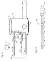
- Figs. 1A, 1B and 1C illustrate a typical, non-limiting example of a junction 100 comprising three inlet pipe stubs 102 (two visible), an outlet pipe stub 104, and a cylindrical wall 106 with a base 108 defining a cavity or chamber 110. Extending from pipe stubs 102 and 104 are pipes 102A and 104A, respectively. Effluent flow reaches chamber 110 via inlet pipes 102A and continues to drain into outlet pipe 104A.
- Chamber 110 allows access to pipe stubs 102 and 104 and pipes 102A and 104A, and is used in the specification as a non-limiting framework for examples of embodiments of the invention.
- the number and relative diameters of inlet pipes 102A or outlet pipes 104A shown are merely exemplary and any practical number of inlet pipes 102A or outlet pipes 104A and diameters thereof may be used in accordance with embodiments of the invention.
- Figs. 1A-1C further show an embodiment of an apparatus 120 for unclogging an obstruction in a drain pipe.
- Apparatus 120 comprises a fluid supply pipe 124 and one or more flushing tubes, represented by four flushing tubes 126A-126D which are shown disposed in one of the inlet pipes 102A and outlet pipe 104A.
- flushing tubes 126 are inserted in all or some of inlet or outlet pipes 102A and 104A, respectively.
- Supply pipe 124 is fitted with a valve 128 for controlling the flow of flushing water, in terms of flow rate (volume per time) and/or velocity and/or pressure.
- chamber 110 in order to install apparatus 120, chamber 110 is exposed, such as by opening a manhole cover under which such junction 100 is typically located, as illustrated in Fig 1A and 1B .
- wall 106 of junction 100 is opened, such as by drilling, and supply pipe 124 is installed in chamber 110 through an opening 132 in wall 106.
- pipe 124 and other pipes (or tubes) 126 are installed via top or side of junction 100.
- pipe 124 can be disposed in any appropriate location and manner.
- supply pipe 124 may be installed through opening 132 made in wall 106; whereas in other embodiments the apparatus includes junction 100 or the junction is pre-formed with a suitable opening to accommodate supply pipe 124.
- Valve 128 can be operated manually, or by other means such as an electro-mechanical mechanism (e.g., a locally or remotely controlled actuator, such as by a solenoid, not shown). In this regard, a system of apparatuses can be operated remotely to flush a series of drain pipes. Valve 128 may be located in the vicinity of junction 100 (e.g. within or adjacent the junction) or outside the vicinity of junction 100. Optionally, the function of valve 128 is carried out by a plurality of valves.
- an electro-mechanical mechanism e.g., a locally or remotely controlled actuator, such as by a solenoid, not shown.
- a system of apparatuses can be operated remotely to flush a series of drain pipes.
- Valve 128 may be located in the vicinity of junction 100 (e.g. within or adjacent the junction) or outside the vicinity of junction 100.
- the function of valve 128 is carried out by a plurality of valves.
- valve 128 When valve 128 is opened, the water provided by supply pipe 124 is flushed into inlet or outlet pipes 102A or 104A thereby clearing or at least partially clearing the obstruction.
- flushing tubes 126A-D are connected to a water source (not shown), such as a regional water supply system or a reservoir, through supply pipe (or pipes) 124.
- the water is optionally supplemented with additional ingredients to assist in unclogging, such as surfactants and/or alkali or acidic chemicals.
- the pressure for flushing the water into pipes (or tubes) 126 is provided by the water supply system or a reservoir, for example, a reservoir in a sufficiently high location relative to junction 100.
- the pressure is provided, or augmented, by a pump 130.
- Pump 130 is manually operated, or operated by other methods such an electro-mechanical mechanism (e.g., a locally or remotely controlled actuator).
- Pipe 118 is, optionally, constructed as a manifold that distributes water from supply pipe 124 to flushing tubes 126.
- Flushing tubes 126 are disposed in inlet or outlet pipes 102A and 104A, respectively, and constructed such that they do not hinder effluent flow in pipes 102A or 104A, or at least not significantly.
- the outer diameters of water flushing tubes 126A-D are small relative to the inner diameters of inlet pipes 102A and outlet pipes 104A; however any appropriate diameter for the flushing pipes can be used.
- flushing tubes 126A-D can be of varying lengths.
- water flushing tubes 126 have an outer diameter of 5% to 10% of the inner diameter of pipes 102A and/or 104A.
- water flushing tubes 126 have a diameter of 10% to 20%, or larger or smaller of pipes 102A and/or 104A.
- water flushing tubes 126 are disposed in a drainage pipe for some length down an outlet pipe and/or up an inlet pipe.
- the length of flushing tube 126 is in the order of 2cm to 50cm; optionally, the length is in the order of 50cm to 1m; optionally, the length is in the order of 1m to several meters such as 2m, 2.5m, 3m or more, or any intermediate length of the recited length ranges.
- a plurality of flushing tubes 126 are disposed in a drainage pipe 102A or 104A, optionally each flushing tube 126 has a different length and/or diameter.
- flushing tubes 126 comprise a plurality of sections 144 that are fastened to each other, for example, by threaded connections 146 or the like, for ease of assembly and.or installation and/or manufacturing.
- flushing tubes 126 are constructed by sections of different diameters, for example, tube 126 is narrower at the end from which flushing water exits than at the end adjacent junction 100.
- Fig. 1D schematically shows flushing tube 126 comprising a relatively large diameter section (or sections) 142 and narrow sections (or section) 144 connected together.
- tube 126 is fitted with a nozzle 148 to thereby eject flushing water in a jet or fast stream in order to unclog an obstruction.
- flushing tubes 126 are flexible, or partially flexible, to ease installation thereof.
- apparatus 120 comprises a tank 112 which can be used to store chemicals that may be added to flushing water in flushing tube 126 from a tank 112 for example via a pipe 114 and regulated by a valve 116.
- FIGS. 2A , 2B and 2C illustrate a manually operated apparatus.
- the apparatus is operated automatically.
- an obstruction is automatically detected or determined (directly or indirectly) and flushing water is automatically ejected to clear the obstruction.
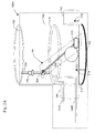
- Figs. 2A and 2B schematically show an apparatus 120A adapted for automatic operation and unclogging of a drain pipe.
- the apparatus comprises a mechanism 200 for detecting or determining that a drain pipe is clogged based on the premise that if and/or when the obstruction is disruptive enough, the effluent flow will be hindered and accumulate (back up) in chamber 110 whereby the effluent level will rise in the chamber.
- mechanism 200 comprises a valve 204 (optionally different and/or a variant of valve 128) and a float 210, both of which are pivotally connected by an arm 206.
- Valve 204 is constructed such that it can open or close water supply pipe 124 according to the height of effluent level 212 in chamber 110, and consequently, the level of float 210, as described below.
- the water supply from source pipe 124 is regulated according to the effluent level 212 and, accordingly, according to the flow (or clogging) of an outlet pipe 104.
- the rate of flow or pressure in flushing tubes 126 is regulated according to the level of float 210 (i.e. effluent level 212) by opening or closing valve 204 responsive to the level of the float 210.
- the opening or closing valve 204 is not linear with float 210 level and, for example, a relatively small or partial rise of float 210 affects an essentially complete opening of valve 204 in order to flush tubes 126. In this manner, even a relatively minor obstruction can be removed before it becomes a more significant obstruction.
- valve 204 the operation of float 210, arm 206 and valve 204 (mechanism 200) is similar to the operation of a toilet flushing mechanism (though in an opposite manner, such that when float 210 is high valve 204 is opened).
- the embodiment shown in Figs. 2A and 2B is provided as a non-limiting example, and other mechanisms may be used for controlling and/or regulating valve 204, and accordingly, of water flow in flushing tubes 126.
- a clog in inlet pipe 102A may also be determined.
- a low effluent level in inlet stub 102 e.g. below the level of a sensor 216, can indicate that an obstruction is present upstream of the sensor.
- Sensor 212 is operably connected to valve 204, whereby a reduced flow, detected by the sensor, opens valve 204.
- a plurality of sensors 212 may be disposed at several levels in inlet stub 102 or inlet pipe 102A, and valve 204 will open (or close) responsive to the lowest (or highest) level of a sensor 212.
- the rate of flushing in flushing tubes 126 is determined is response to the effluent level detected by sensor 214 and/or 216.
- the water sensor(s) 214 and/or 216 may comprise, for example, two electric electrodes with different electric potentials, such that when covered with water/effluent (or other conductive medium) electric current flows under the potential difference, which effects (e.g. by using an amplifier) the opening or closing of valve 204.
- sensor(s) 214 and/or 216 comprise a flow rate meter and/or flow velocity meter disposed in inlet stub 102 or outlet stub 104, so that valve 204 is opened or closed according to the flow in inlet stub 102 or outlet stub 104. For example, when the effluent flow rate is lower than typically expected, valve 204 is opened to flush tubes 126 in inlet pipe 102A or outlet pipe 104A.
- the water sensor or flow meter 212 is disposed in chamber 110, and functions as described above.
- the drain is not conductive, other sensors sensitive to the effluent composition may be used.
- valve 204 and/or the sensors described above are used to regulate the pressure of the flushing water. For example, by regulating pump 130 or by other methods such as regulating the water supply pressure by an auxiliary valve.
- apparatus 120 is installed on an ad-hoc basis. For example, when a clog is identified or suspected, junction 100 is accessed (e.g., by opening a cover of manhole in which the junction is placed) and apparatus 120 is installed to provide water from supply pipe 124 to tubes 126. Optionally or alternatively, apparatus 120 is left installed for future use, optionally with valve 208 closed to save water and it may be assembled with mechanism 200 and/or tank 112. In some embodiments of the invention, apparatus 120 or 120A is installed as a preventive measure, that is, to be ready in case of a clogging and, particularly for apparatus 120A, to operate automatically when clogging is determined or identified.
- junction 100 is manufactured and/or supplied with apparatus 120 and/or 120A, at least partially.
- junction 100 comprises a section of supply pipe 124 and/or manifold 118 and/or sections of tubes 126 in inlet and/or outlet stubs 102 and 104, and/or optionally valve 128 or 204.
- the chemicals are supplied as part of junction 100, optionally in a bag or container such as tank 112.
- apparatus 120 and/or 120A are provided as a kit.
- maintenance personnel may acquire the kit and install it in a drain pipe or junction such as junction 100 or other such plumbing system.
- additional pipes or pipe (or tube) sections may be acquired in order to extend pipes 126, as well as chemicals and pumps.
- Fig. 3 schematically shows an exemplary kit 300 for flushing an obstruction in a drain pipe, comprising supply pipe 124, valve 204, arm 206 and float 210, as well as tube 126 sections 142, 144, connection sections 146 and ejection nozzle 148.
- the kit comprises at least one chemical for aiding in unclogging an obstruction.
- the kit comprises a tank, for example, such as tank 112 for holding flushing fluid.
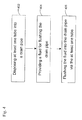
- Fig. 4 shows a flowchart of an embodiment of a method for unclogging an obstruction in a drain pipe, comprising: disposing at least one tube into a drain pipe (402), providing water for flushing the drain pipe (404), and flushing the water into the drain pipe via the at least one tube (406).
Landscapes
- Engineering & Computer Science (AREA)
- Mechanical Engineering (AREA)
- Health & Medical Sciences (AREA)
- Life Sciences & Earth Sciences (AREA)
- Hydrology & Water Resources (AREA)
- Public Health (AREA)
- Water Supply & Treatment (AREA)
- Sink And Installation For Waste Water (AREA)
- Cleaning In General (AREA)
- Sewage (AREA)
Applications Claiming Priority (1)
| Application Number | Priority Date | Filing Date | Title |
|---|---|---|---|
| IL190648A IL190648A (en) | 2008-04-07 | 2008-04-07 | Apparatus, method and kit for unclogging an obstruction in a pipe and a junction having a plurality of pipe stubs therefor |
Publications (2)
| Publication Number | Publication Date |
|---|---|
| EP2108752A2 true EP2108752A2 (fr) | 2009-10-14 |
| EP2108752A3 EP2108752A3 (fr) | 2013-01-02 |
Family
ID=40897479
Family Applications (1)
| Application Number | Title | Priority Date | Filing Date |
|---|---|---|---|
| EP20090275022 Withdrawn EP2108752A3 (fr) | 2008-04-07 | 2009-04-07 | Appareil et procédé pour déboucher un tuyau |
Country Status (3)
| Country | Link |
|---|---|
| US (1) | US8122902B2 (fr) |
| EP (1) | EP2108752A3 (fr) |
| IL (1) | IL190648A (fr) |
Cited By (3)
| Publication number | Priority date | Publication date | Assignee | Title |
|---|---|---|---|---|
| US20130023842A1 (en) * | 2010-03-23 | 2013-01-24 | Wuhan Vsd Medical Science & Technology Co., Ltd. | Medical vacuum sealing drainage device |
| WO2016207716A1 (fr) * | 2015-06-26 | 2016-12-29 | Dyteqta Limited | Dispositif de nettoyage de tuyau de drainage et procédé de nettoyage |
| WO2022147544A1 (fr) * | 2021-01-04 | 2022-07-07 | Saudi Arabian Oil Company | Déblocage simultané de multiples raccords de soupape |
Families Citing this family (5)
| Publication number | Priority date | Publication date | Assignee | Title |
|---|---|---|---|---|
| EP3535068A1 (fr) | 2016-11-01 | 2019-09-11 | Atam Group Limited | Dispositif de nettoyage de tuyau |
| US10323397B2 (en) * | 2017-02-28 | 2019-06-18 | Norman Mimms | Plumbing insert cleansing device |
| US10682676B2 (en) * | 2018-05-02 | 2020-06-16 | Jack W. Raynes, II | Self cleaning condensate drain pressure trap |
| GB201912788D0 (en) * | 2019-09-05 | 2019-10-23 | Atam Group Ltd | A method of building cleamn and inspected piping systems |
| CN214144015U (zh) * | 2021-01-04 | 2021-09-07 | 沈阳快速路建设投资有限公司 | 一种市政排水排污管道 |
Citations (4)
| Publication number | Priority date | Publication date | Assignee | Title |
|---|---|---|---|---|
| US4083661A (en) | 1976-05-05 | 1978-04-11 | Clow Corporation | Pneumatic sewage ejector |
| DE3300489A1 (de) | 1983-01-08 | 1984-07-12 | Klaus-Ulrich Dipl.-Ing. Giehl (FH), 5239 Heimborn | Schwimmergesteuerter rechen |
| DE3822555A1 (de) | 1988-01-25 | 1989-08-03 | Giehl Klaus Ulrich | Drosselvorrichtung fuer kanalisationsanlagen |
| US5967175A (en) | 1996-02-15 | 1999-10-19 | Direct, Plumbing, Heating & Rooter, Inc. | Waste line stoppage detector and automatic water shutoff system |
Family Cites Families (13)
| Publication number | Priority date | Publication date | Assignee | Title |
|---|---|---|---|---|
| US1745923A (en) * | 1929-08-09 | 1930-02-04 | Calfus F Frizzell | Sewer plug |
| US3937404A (en) * | 1975-06-09 | 1976-02-10 | Johnson Arthur L | Drain declogging device |
| US4141090A (en) * | 1977-02-07 | 1979-02-27 | Thomas Rowan | Trap and drain flush out kit |
| US4736968A (en) * | 1984-08-16 | 1988-04-12 | Keith Glegg | Coupling device for coupling a hose to a drain pipe |
| US4944320A (en) * | 1987-06-09 | 1990-07-31 | Airrigation Engineering Co., Inc. | Chemical control of root growth in sewers and the like |
| US4998412A (en) * | 1990-01-22 | 1991-03-12 | Joel Bell | Blockage alert and purge system |
| DE4137768C1 (en) * | 1991-11-16 | 1992-10-01 | Lothar Dipl.-Ing. 6204 Taunusstein De Steinhardt | Automatic hoist with downwards open bell - has outlet tube, whose top end retains movably top-open float pot |
| US5964238A (en) * | 1996-02-09 | 1999-10-12 | Beth Good Junkin | Condensate discharge line treatment |
| US5921207A (en) * | 1997-05-06 | 1999-07-13 | Disalvo; Joseph | Automatic flushing system for water tank |
| DE10030201C1 (de) * | 2000-06-20 | 2001-10-04 | Otte Bernd | Düse zur Reinigung von Kanälen und Verfahren zur Reinigung von Kanälen mittels derselben |
| US20020124300A1 (en) * | 2000-09-19 | 2002-09-12 | Eskandar Rasaei | Flushing device for toilets |
| US6345410B1 (en) * | 2001-01-26 | 2002-02-12 | John G. Baker | Drain opening device |
| FR2879978B1 (fr) * | 2004-12-27 | 2008-07-18 | Sanitra Services Sa | Vehicule de curage |
-
2008
- 2008-04-07 IL IL190648A patent/IL190648A/en active IP Right Grant
-
2009
- 2009-04-07 EP EP20090275022 patent/EP2108752A3/fr not_active Withdrawn
- 2009-04-07 US US12/419,313 patent/US8122902B2/en not_active Expired - Fee Related
Patent Citations (4)
| Publication number | Priority date | Publication date | Assignee | Title |
|---|---|---|---|---|
| US4083661A (en) | 1976-05-05 | 1978-04-11 | Clow Corporation | Pneumatic sewage ejector |
| DE3300489A1 (de) | 1983-01-08 | 1984-07-12 | Klaus-Ulrich Dipl.-Ing. Giehl (FH), 5239 Heimborn | Schwimmergesteuerter rechen |
| DE3822555A1 (de) | 1988-01-25 | 1989-08-03 | Giehl Klaus Ulrich | Drosselvorrichtung fuer kanalisationsanlagen |
| US5967175A (en) | 1996-02-15 | 1999-10-19 | Direct, Plumbing, Heating & Rooter, Inc. | Waste line stoppage detector and automatic water shutoff system |
Cited By (7)
| Publication number | Priority date | Publication date | Assignee | Title |
|---|---|---|---|---|
| US20130023842A1 (en) * | 2010-03-23 | 2013-01-24 | Wuhan Vsd Medical Science & Technology Co., Ltd. | Medical vacuum sealing drainage device |
| WO2016207716A1 (fr) * | 2015-06-26 | 2016-12-29 | Dyteqta Limited | Dispositif de nettoyage de tuyau de drainage et procédé de nettoyage |
| CN107847988A (zh) * | 2015-06-26 | 2018-03-27 | 迪泰克塔有限公司 | 排水管清洁装置和清洁方法 |
| US10843237B2 (en) | 2015-06-26 | 2020-11-24 | Dyteqta International Limited | Drain pipe cleaning device and method of cleaning |
| WO2022147544A1 (fr) * | 2021-01-04 | 2022-07-07 | Saudi Arabian Oil Company | Déblocage simultané de multiples raccords de soupape |
| US11839908B2 (en) | 2021-01-04 | 2023-12-12 | Saudi Arabian Oil Company | Simultaneously unblocking multiple valve fittings |
| US12208429B2 (en) | 2021-01-04 | 2025-01-28 | Saudi Arabian Oil Company | Simultaneously unblocking multiple valve fittings |
Also Published As
| Publication number | Publication date |
|---|---|
| IL190648A (en) | 2011-11-30 |
| US8122902B2 (en) | 2012-02-28 |
| US20090188568A1 (en) | 2009-07-30 |
| IL190648A0 (en) | 2009-02-11 |
| EP2108752A3 (fr) | 2013-01-02 |
Similar Documents
| Publication | Publication Date | Title |
|---|---|---|
| US8122902B2 (en) | Apparatus and method for unclogging a pipe | |
| US3923657A (en) | Combined septic tank inlet pipe sight glass end plug and tank aerator system | |
| US9182181B2 (en) | Condensate drain trap for an air conditioning system | |
| US6889395B1 (en) | Flush reservoir | |
| AU2002100710B4 (en) | Greywater diversion vessell assembly | |
| CA2678710C (fr) | Dispositif d'evacuation du trop-plein d'egout | |
| KR100902278B1 (ko) | 체크밸브를 갖는 물저장부가 구비된 관정 오염방지장치 | |
| JP2001107443A (ja) | 真空排水システム内の垂直立上り管用曝気装置 | |
| JPH09151534A (ja) | 下水管作業用循環排水装置 | |
| EP3204562B1 (fr) | Ensemble constitué d'un égout et d'un système de détection d'obturation d'égout | |
| US7336190B2 (en) | Early detection and advanced warning “waste is backing up” apparatus and method | |
| WO2010142950A1 (fr) | Système de collecte d'eau de pluie | |
| JP2003268755A (ja) | 自動給水装置 | |
| CZ20021493A3 (cs) | Způsob a zařízení k periodickému proplachování potrubí odpadních vod | |
| FI77911C (fi) | Foerfarande foer stoetvis transport av vaetska. | |
| US20060191577A1 (en) | Hydro-controller | |
| US6684902B1 (en) | Dual sensor liquid accumulator | |
| EP2904163B1 (fr) | Élément de canalisation, système de vidange de tuyau d'évacuation et procédé de déconnexion provisoire d'un tuyau de sortie d'un bâtiment d'un collecteur d'égout | |
| EP1693524A1 (fr) | Appareil de contrôle d'eau de pluie | |
| KR101774986B1 (ko) | 유체 역류 방지 장치 | |
| HU208177B (en) | Sampler for liquids, in particular to small-dimension sewage conduits | |
| EP1307620B1 (fr) | Reservoir de liquide, dispositif de pompage pour un tel reservoir, et procede de vidange de reservoir de liquide | |
| JP2025066895A (ja) | 機能枡 | |
| WO2026093813A1 (fr) | Ensemble d'alimentation en eau amélioré pour un véhicule de secours et véhicule de secours équipé d'un tel ensemble d'alimentation en eau | |
| JP2000355970A (ja) | 汚水槽用スカム除去装置 |
Legal Events
| Date | Code | Title | Description |
|---|---|---|---|
| PUAI | Public reference made under article 153(3) epc to a published international application that has entered the european phase |
Free format text: ORIGINAL CODE: 0009012 |
|
| AK | Designated contracting states |
Kind code of ref document: A2 Designated state(s): AT BE BG CH CY CZ DE DK EE ES FI FR GB GR HR HU IE IS IT LI LT LU LV MC MK MT NL NO PL PT RO SE SI SK TR |
|
| PUAL | Search report despatched |
Free format text: ORIGINAL CODE: 0009013 |
|
| AK | Designated contracting states |
Kind code of ref document: A3 Designated state(s): AT BE BG CH CY CZ DE DK EE ES FI FR GB GR HR HU IE IS IT LI LT LU LV MC MK MT NL NO PL PT RO SE SI SK TR |
|
| RIC1 | Information provided on ipc code assigned before grant |
Ipc: B08B 9/032 20060101ALI20121129BHEP Ipc: E03F 9/00 20060101AFI20121129BHEP |
|
| STAA | Information on the status of an ep patent application or granted ep patent |
Free format text: STATUS: THE APPLICATION IS DEEMED TO BE WITHDRAWN |
|
| 18D | Application deemed to be withdrawn |
Effective date: 20130703 |