EP2108868B1 - Robinet d'arrêt pour le domaine d'installation - Google Patents
Robinet d'arrêt pour le domaine d'installation Download PDFInfo
- Publication number
- EP2108868B1 EP2108868B1 EP09151013A EP09151013A EP2108868B1 EP 2108868 B1 EP2108868 B1 EP 2108868B1 EP 09151013 A EP09151013 A EP 09151013A EP 09151013 A EP09151013 A EP 09151013A EP 2108868 B1 EP2108868 B1 EP 2108868B1
- Authority
- EP
- European Patent Office
- Prior art keywords
- shut
- cock
- sheet metal
- sections
- limit stop
- Prior art date
- Legal status (The legal status is an assumption and is not a legal conclusion. Google has not performed a legal analysis and makes no representation as to the accuracy of the status listed.)
- Active
Links
Images
Classifications
-
- F—MECHANICAL ENGINEERING; LIGHTING; HEATING; WEAPONS; BLASTING
- F16—ENGINEERING ELEMENTS AND UNITS; GENERAL MEASURES FOR PRODUCING AND MAINTAINING EFFECTIVE FUNCTIONING OF MACHINES OR INSTALLATIONS; THERMAL INSULATION IN GENERAL
- F16K—VALVES; TAPS; COCKS; ACTUATING-FLOATS; DEVICES FOR VENTING OR AERATING
- F16K27/00—Construction of housing; Use of materials therefor
- F16K27/06—Construction of housing; Use of materials therefor of taps or cocks
- F16K27/067—Construction of housing; Use of materials therefor of taps or cocks with spherical plugs
-
- F—MECHANICAL ENGINEERING; LIGHTING; HEATING; WEAPONS; BLASTING
- F16—ENGINEERING ELEMENTS AND UNITS; GENERAL MEASURES FOR PRODUCING AND MAINTAINING EFFECTIVE FUNCTIONING OF MACHINES OR INSTALLATIONS; THERMAL INSULATION IN GENERAL
- F16K—VALVES; TAPS; COCKS; ACTUATING-FLOATS; DEVICES FOR VENTING OR AERATING
- F16K5/00—Plug valves; Taps or cocks comprising only cut-off apparatus having at least one of the sealing faces shaped as a more or less complete surface of a solid of revolution, the opening and closing movement being predominantly rotary
- F16K5/06—Plug valves; Taps or cocks comprising only cut-off apparatus having at least one of the sealing faces shaped as a more or less complete surface of a solid of revolution, the opening and closing movement being predominantly rotary with plugs having spherical surfaces; Packings therefor
- F16K5/0626—Easy mounting or dismounting means
- F16K5/0642—Easy mounting or dismounting means the spherical plug being insertable from one and only one side of the housing
Definitions
- the present invention relates to a shut-off valve for the installation area for shutting off a fluid-flow line, with at least two housing-forming connecting pieces, which define a flow path in the assembled state, and with a rotatably mounted in the housing shut-off with at least two shut-off sections, said Shut-off between a closed position, blocked in the at least one of the shut-off of the shut-off the flow path, and an open position in which both shut-off sections enable the flow path, is movable.
- a stopcock of the aforementioned type, in particular a ball, cylinder or cone tap has long been known and is used in various technical applications in various sizes. There are two- and multi-channel stopcocks known.
- the housing of the stopcock is usually composed of two screwed together and glued spigot.
- the connecting pieces are used to connect the stopcock to a pipe through which a fluid flows.
- the connection of the line sections to the connecting pieces can be done by screwing, welding or pressing.
- a shut-off body By an actuating element, which may be driven, for example, mechanically, electrically, pneumatically, electromagnetically or hydraulically, a shut-off body is rotated within the housing of the stopcock perpendicular to the flow path. The shut-off closes in the closed position of the stopcock with one of its sections the flow channel by the shut-off block the flow path. By turning the shut-off body via the actuating element in an open position, the shut-off sections of the shut-off body release the flow path.
- the shut-off can be spherical, spherical or cylindrical and consists of a body made of solid material, in the case of a conical shut-off, ie a solid ball, with a passage hole.
- the solid body is rotated on a lathe from a blank, usually a cylinder whose diameter corresponds at least to the later diameter at the widest point of the solid body to be produced, that is, for example, the diameter of the solid sphere.
- a blank usually a cylinder whose diameter corresponds at least to the later diameter at the widest point of the solid body to be produced, that is, for example, the diameter of the solid sphere.
- a relatively large part of the blank must therefore be turned off, which leads to an increased production cost. Added to this is the additional expense of producing the passage bore.
- shut-off valve for the installation area for shutting off a fluid-flow line, with two housing-forming connecting pieces which define a flow path in the assembled state, and a rotatably arranged in the housing shut-off with at least two shut-off sections, the shut-off body between a closed position, in of the blocked at least one of the shut-off portions of the shut-off the flow path, and an open position in which both shut-off sections enable the flow path, is movable, wherein the shut-off body is formed by a sheet metal forming part.
- a stopcock is also from the DE 195 00 475 A1 known.
- the ball valve on a hollow ball and recessed areas of the ball outer surface, which allow fluid flow to the outside of the ball when the ball valve is partially open.
- the previously derived and indicated object is according to a first teaching of the present invention in a Stopcock of the type described above achieved in that the stop piece (10, 10 ') of a hook-shaped sheet metal portion (12,12') is formed.
- Blechumformteil is used instead of a solid body, for example, instead of a solid ball, eliminates the high cost of machining on the lathe. Also, the high material consumption associated with the machining - a large part of the blank is turned off and unused waste - is eliminated, since according to the invention for the production of the shut-off only a sheet metal part, which at least partially corresponds to the later shut-off, stamped and formed.
- the punching and forming can take place successively or preferably even in a single work step.
- said Blechumformteil is naturally already hollow from the outset, so that either with appropriate shaping of the punched and formed sheet metal parts with a corresponding recess no through hole must be made or in the case of subsequent production, the passage hole can be produced much easier.
- the production of the shut-off as Blechumformteil is thus less expensive than the production of a solid body.
- shut-off body formed by a sheet metal forming part Another advantage of a shut-off body formed by a sheet metal forming part is that an additional surface coating can be dispensed with.
- a solid body for example, a solid sphere
- the shut-off body is provided with at least one Drehwegbegrenzungs coupled.
- the Drehwegbegrenzungs issued gives the user during the operation of the stopcock, ie when turning the shut-off, the closed position and / or the open position exactly.
- the Drehwegbegrenzungs observed for the first time part of the shut-off and is no longer, as usual in the prior art, pressed by attacks on the outside of the housing or molded.
- the molded on the outside of the housing attacks have so far increased the amount of work in the production of the stopcock and also contained the risk of damage to the Drehwegbegrenzungs adopted because the attacks were unprotected.
- the Drehwegbegrenzungs has a arranged on the shut-off stop piece and a cooperating, the rotary path of the shut-off limiting and arranged in the housing stop counterpart.
- the stop piece and / or the stop counterpart formed integrally with the shut-off body or the housing, but can also be molded.
- the stop piece formed by a hook-shaped sheet metal section is, which is preferably an integral part of the shut-off, so it is designed in one piece with the rest of sheet metal forming part.
- This stop piece may for example be part of a flattened portion and be formed by one or more recesses in this part of the shut-off.
- the stop counterpart can be formed by a projecting, in particular bolt-shaped housing portion, which is preferably an integral part of the housing, so it is designed in one piece.
- the protruding or bolt-shaped housing section can be arranged on the inside of the housing wall in relation to the opening provided in the housing for the actuating element.
- the stop counterpart may also be a subsequently molded bolt or other projection that may be positioned in the housing.
- the described stop piece in particular the hook-shaped sheet metal section of the shut-off but not only serves to Drehwegbegrenzung.
- the closed position is further generated by the contact of the stop piece with the stop counterpart, in particular the bolt-shaped housing portion, an increased pressure from the shut-off on the seals in the housing. This optimized pressure guarantees long-term tightness in the closed position.
- the sheet metal forming part is an at least partially spherical, conical or cylindrical component, wherein the shut-off sections are preferably completely bent.
- any standard shut-off body shape can be produced from a blank sheet metal.
- the shut-off sections which are the Close the connecting piece and thus block the flow path in order to shut off the line through which the fluid can flow, bent spherically around a point.
- the Absperrabitese are cylindrical and bent in the case of a cone conically around an axis. The curved shut-off ensure that during the rotation of the shut-off between the closed position and the open position, the shut-off evenly on the inside of the connecting piece or appropriately arranged seals to the plant.
- the sheet metal forming part is a ball with at least one flattened portion, in particular with at least two flattened portions, which are preferably arranged opposite one another.
- One of the flattened portions may extend transversely to the axis of rotation of the shut-off and have a recess into which engages an actuating element for producing a rotationally fixed connection with the shut-off. With such an actuator then the shut-off can be adjusted between the closed position and the open position.
- Another flattened portion which may be opposite to the first flattened portion and preferably also transverse to the axis of rotation of the shut-off body, may be used as part of a rotary travel limiting device which will be described in more detail below.
- the flattened portion may also have one or possibly more recesses.
- the sheet metal forming part forming the shut-off body can be a component produced by stamping and forming, for example bending. It is conceivable, for example, to produce a ball as a sheet metal, stamped and bent part in a follower tool. It is conceivable to produce or assemble the sheet metal forming part from a single blank sheet or from a plurality of moldings produced by stamping and bending. In particular, two mold parts, each forming one half of the Blechumformteils be composed of a shut-off.
- the stop piece and / or the stop counterpart does not project into the flow path, so preferably in the housing or in the sheet metal formed part integrated that it does not have the inner Surface of the sheet metal forming part protrudes.
- the connecting pieces are inserted into one another and pressed in an overlapping region, in particular by cold forming.
- a sealing element arranged in this region, for example a sealing ring, preferably an O-ring.
- the sheet metal forming part may be composed of a plurality of moldings produced by punching and bending.
- the Drehwegbegrenzungs liked can advantageously be designed as previously described in detail.
- a stopcock for the installation area with such Drehwegbegrenzungs leads to a significantly reduced production costs, since the Wheelwegbegrenzungs featured is integrated directly into the shut-off and not separately in a separate process step outside the housing must be formed. In addition, the Drehwegbegrenzungs observed is better protected by their arrangement in the interior of the housing of the stopcock.
- connecting pieces can be inserted into one another and pressed in an overlapping region, in particular by cold forming.
- a sealing element preferably a sealing ring, for example an O-ring, is arranged in the overlapping region between the nested connecting pieces.
- stopcock leads to a reduced production cost, since on the one hand to the use of an expensive adhesive, which must also be applied in a separate step, can be dispensed with. Also, no thread must be provided at the junction of the two connecting pieces, so in the overlapping area, which would also require a separate step.
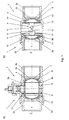
- a shut-off valve 1 for the installation area for shutting off a fluid-flow line (not shown).
- the stopcock 1 has a housing 2, which is formed by two connecting pieces 3a and 3b, which in the present embodiment by cold forming in an overlapping region 14th pressed together.
- a sealing ring 15 in the form of an O-ring serves to seal the interior from the environment.
- a shut-off body 4 is rotatably arranged, which has two shut-off sections 5a and 5b.
- the shut-off 4 is between a closed position, the in Fig. 1 is shown and in which the shut-off sections 5a and 5b block the flow path S, and an open position, not shown, in which both shut-off sections 5a and 5b enable the flow path, movable.
- the shut-off body 4 is formed in the present case of a sheet-metal forming part 6, namely a ball 7 with two opposite flattened portions 8a and 8b.
- the sheet metal forming part 6 is a manufactured by punching and bending component with a uniform wall thickness.
- the flattened sections are clearly in Fig. 1a ) to recognize.
- the in Fig. 1a ) flattened portion 8a shown above has a recess 15 into which an actuating element rotatably engages, via which the shut-off body 4 can be rotated from the illustrated closed position into the open position, not shown.
- Fig. 1a The in Fig. 1a ) shown below flattened portion 8b is part of two arranged in the lower part of the stopcock 1 Drehwegbegrenzungs Rheinen 9 and 9 ', which in the following with reference to Fig. 1b ) to be discribed.
- Fig. 1b shows a 90 ° about the longitudinal axis opposite Fig. 1a ) rotated cross section through the stopcock 1.
- the flattened portion 8b forms two rotationally symmetrical to the axis of rotation of the shut-off 4 arranged stop pieces 10 and 10 'in the form of hook-shaped sheet metal sections 12 and 12'.
- the two hook-shaped sheet metal sections 12 and 12 ' are an integral part of the Blechumformteils 6 and were also produced in the production of Blechumformteils 6 by punching and bending.
- the bolt-shaped housing sections 13 and 13 ' were welded after the production of the connecting piece 3b in the interior of the same.
- shut-off 4 of the in Fig. 1b turned from the closed position shown above counterclockwise, so first solves the respective stop piece 10 and 10 'from the respective stop counterpart 11 or 11'. Will the Shut-off 4 further turned up to the open position, so pushes the respective stop piece 10 or 10 'to the respective other stop counterpart 11 or 11', whereby the optimal open position is defined. It is thus realized a Drehwegbegrenzungs adopted for defining the closed position and a Drehwegbegrenzungs adopted for defining the open position with simple means in the interior of the housing 2 of the stopcock 1.
Landscapes
- Engineering & Computer Science (AREA)
- General Engineering & Computer Science (AREA)
- Mechanical Engineering (AREA)
- Taps Or Cocks (AREA)
- External Artificial Organs (AREA)
- Valve Housings (AREA)
- Analysing Materials By The Use Of Radiation (AREA)
- Infusion, Injection, And Reservoir Apparatuses (AREA)
Claims (14)
- Robinet d'arrêt (1) pour le domaine de l'installation pour fermer une conduite traversée par un liquide,- avec au moins deux tubulures de raccordement (3a, 3b) formant un carter (2) et qui définissent à l'état monté un trajet d'écoulement (S) et- avec un corps d'arrêt (4) disposé de manière rotative dans le carter (2) avec au moins deux sections d'arrêt (5a, 5b),le corps d'arrêt (4) étant mobile entre une position de fermeture dans laquelle au moins l'une des sections d'arrêt (5a, 5b) du corps d'arrêt (4) bloque le trajet d'écoulement (S) et une position d'ouverture dans laquelle les deux sections de d'arrêt (5a, 5b) libèrent le trajet d'écoulement (S),
le corps de d'arrêt (4) étant formé par une pièce façonnée en tôle (6),
le corps d'arrêt (4) étant muni au moins d'un dispositif de limitation de rotation (9, 9'), le dispositif de limitation de rotation (9, 9') présentant une pièce de butée (10, 10') disposée sur le corps d'arrêt (4) et coopérant avec une pièce de contrebutée (11, 11') disposée dans le carter (2) et limitant la rotation du corps d'arrêt (4),
caractérisé en ce que la pièce de butée (10, 10') est formée par une section de tôle (12, 12') en forme de crochet. - Robinet d'arrêt (1) selon la revendication 1, caractérisé en ce que la pièce de contrebutée (11, 11') est formée par une section de carter (13, 13') saillante, en particulier en forme de boulon.
- Robinet d'arrêt (1) selon la revendication 2, caractérisé en ce que la section de tôle (12, 12') en forme de crochet fait partie intégrante du corps d'arrêt (4) et/ou la section de carter (13, 13') saillante fait partie intégrante du carter (2).
- Robinet d'arrêt (1) pour le domaine de l'installation pour fermer une conduite traversée par un liquide,- avec au moins deux tubulures de raccordement (3a, 3b) formant un carter (2) et définissent à l'état monté un trajet d'écoulement (S) et- avec un corps d'arrêt (4) disposé de manière rotative dans le carter (2) avec au moins deux sections d'arrêt (5a, 5b),le corps d'arrêt (4) étant mobile entre une position de fermeture dans laquelle au moins l'une des sections d'arrêt (5a, 5b) du corps d'arrêt (4) bloque le trajet d'écoulement (S) et une position d'ouverture dans laquelle les deux sections de d'arrêt (5a, 5b) libèrent le trajet d'écoulement (S)
le corps de d'arrêt (4) étant formé par une pièce façonnée en tôle (6),
le corps d'arrêt (4) étant muni au moins d'un dispositif de limitation de rotation (9, 9'), le dispositif de limitation de rotation (9, 9') présentant une pièce de butée (10, 10') disposée sur le corps d'arrêt (4) et coopérant avec une pièce de contrebutée (11, 11') disposée dans le carter (2) et limitant la rotation du corps d'arrêt (4),
caractérisé en ce que la pièce de contrebutée (11, 11') est formée par une section de tôle en forme de boulon (13, 13'). - Robinet d'arrêt (1) selon la revendication 4, caractérisé en ce que la pièce de butée (10, 10') est formée par une section de tôle (12, 12') en forme de crochet.
- Robinet d'arrêt (1) selon la revendication 5, caractérisé en ce que la section de tôle (12, 12') en forme de crochet fait partie intégrante du corps d'arrêt (4) et/ou la section de carter (13, 13') saillante fait partie intégrante du carter (2).
- Robinet d'arrêt (1) selon l'une des revendications précédentes, caractérisé en ce que les tubulures de raccordement (3a, 3b) sont emboitées l'une dans l'autre et sont compressées dans une zone de chevauchement (14).
- Robinet d'arrêt (1) selon l'une des revendications précédentes, caractérisé en ce que la pièce façonnée en tôle (6) est un composant de forme sphérique, conique ou cylindrique au moins par section, les sections d'arrêt (5a, 5b) étant de préférence complètement coudées.
- Robinet d'arrêt (1) selon la revendication 8, caractérisé en ce que la pièce façonnée en tôle (6) est une sphère (7) avec au moins une section aplatie (8a;8b) en particulier avec au moins deux sections aplaties (8a, 8b) qui sont disposées de préférence en vis-à-vis.
- Robinet d'arrêt (1) selon l'une des revendications précédentes, caractérisé en ce que l'épaisseur de paroi au moins des sections d'arrêt (5a, 5b), en particulier de l'ensemble de la pièce façonnée en tôle (6), est régulière.
- Robinet d'arrêt (1) selon l'une des revendications précédentes, caractérisé en ce que la pièce façonnée en tôle (6) est un composant fabriqué par poinçonnage et pliage.
- Robinet d'arrêt (1) selon l'une des revendications précédentes, caractérisé en ce que la pièce façonnée en tôle (6) est composée de plusieurs pièces façonnées fabriquées par poinçonnage et pliage.
- Robinet d'arrêt (1) selon l'une des revendications précédentes, caractérisé en ce que la pièce de butée (10, 10') et/ou la pièce de contrebutée (11, 11') ne s'engage pas dans le trajet d'écoulement (S).
- Robinet d'arrêt (1) selon l'une des revendications précédentes, caractérisé en ce qu'il est disposé dans la zone de chevauchement (14) entre les tubulures de raccordement (3a, 3b) emboîtées les unes dans les autres une bague d'étanchéité (15).
Applications Claiming Priority (1)
| Application Number | Priority Date | Filing Date | Title |
|---|---|---|---|
| DE102008018507.8A DE102008018507B4 (de) | 2008-04-10 | 2008-04-10 | Absperrhahn für den Installationsbereich |
Publications (2)
| Publication Number | Publication Date |
|---|---|
| EP2108868A1 EP2108868A1 (fr) | 2009-10-14 |
| EP2108868B1 true EP2108868B1 (fr) | 2011-03-02 |
Family
ID=40823075
Family Applications (1)
| Application Number | Title | Priority Date | Filing Date |
|---|---|---|---|
| EP09151013A Active EP2108868B1 (fr) | 2008-04-10 | 2009-01-21 | Robinet d'arrêt pour le domaine d'installation |
Country Status (5)
| Country | Link |
|---|---|
| US (1) | US8628058B2 (fr) |
| EP (1) | EP2108868B1 (fr) |
| AT (1) | ATE500454T1 (fr) |
| DE (2) | DE102008018507B4 (fr) |
| DK (1) | DK2108868T3 (fr) |
Families Citing this family (2)
| Publication number | Priority date | Publication date | Assignee | Title |
|---|---|---|---|---|
| DE102010033952B4 (de) | 2010-08-10 | 2012-05-03 | Viega Gmbh & Co. Kg | Absperrhahn für den Installationsbereich |
| DE102016223444B3 (de) * | 2016-11-25 | 2018-05-24 | smk systeme metall kunststoff gmbh & co. kg | Optimiertes Klappenventil für ein Abgasklappensystem sowie Herstellungsverfahren dafür |
Family Cites Families (18)
| Publication number | Priority date | Publication date | Assignee | Title |
|---|---|---|---|---|
| FR1171525A (fr) * | 1956-03-21 | 1959-01-27 | Cameron Iron Works Inc | Robinet à clé |
| GB926750A (en) | 1962-03-19 | 1963-05-22 | Neue Argus Gmbh | Process for producing without cutting, a spherical plug for shut-off cocks |
| US3348804A (en) * | 1964-06-10 | 1967-10-24 | Grove Valve & Regulator Co | Valve construction |
| US3689027A (en) * | 1970-10-08 | 1972-09-05 | Gen Ind Inc | Ball for ball valve |
| US3679170A (en) * | 1971-03-08 | 1972-07-25 | Dow Chemical Co | Ball valve with positive locking mechanism |
| US3737145A (en) * | 1971-08-02 | 1973-06-05 | Walworth Co | Fabricated valve ball |
| SE356113B (fr) * | 1971-08-16 | 1973-05-14 | Saab Scania Ab | |
| US3966119A (en) * | 1972-09-06 | 1976-06-29 | Avm Corporation | Valve assembly with plural flow path control |
| US3961405A (en) * | 1973-09-27 | 1976-06-08 | Milwaukee Valve Company, Inc. | Method of fabricating a butterfly valve |
| DE2365926A1 (de) * | 1973-12-22 | 1977-02-10 | Randerath Michael | Hahn mit kueken |
| FR2315649A1 (fr) * | 1975-06-27 | 1977-01-21 | Provence Const Met | Robinets a boisseau tournant perfectionnes |
| FR2334901A1 (fr) * | 1975-12-09 | 1977-07-08 | Legris France Sa | Perfectionnement aux robinets a tournant a portee de joint spherique |
| US4180244A (en) * | 1977-05-23 | 1979-12-25 | Hubner-Vamag Aktiengesellschaft & Co. Kommanditgesellschaft | Stopcock formed of sheet metal |
| DE3540514A1 (de) | 1985-11-15 | 1987-05-27 | Klinger Ag | Rohrarmatur, insbesondere absperrorgan |
| DE19500475C2 (de) * | 1995-01-10 | 2001-09-27 | Schatz Thermo Gastech Gmbh | Absperr- oder Drosselventil mit drehbarer Ventilklappe |
| US6173940B1 (en) * | 1999-06-30 | 2001-01-16 | Premier Farnell Corp. | Valve ball configuration |
| US6899599B1 (en) * | 2004-05-25 | 2005-05-31 | Chiang Hsiang-Hui | Manufacturing process to make a valve ball |
| DE202006001292U1 (de) * | 2006-01-27 | 2006-04-06 | Theodor Heimeier Metallwerk Gmbh | Thermostatventilunterteil für Heiz- und/oder Kühlanlagen |
-
2008
- 2008-04-10 DE DE102008018507.8A patent/DE102008018507B4/de active Active
-
2009
- 2009-01-21 DK DK09151013.1T patent/DK2108868T3/da active
- 2009-01-21 DE DE502009000407T patent/DE502009000407D1/de active Active
- 2009-01-21 EP EP09151013A patent/EP2108868B1/fr active Active
- 2009-01-21 AT AT09151013T patent/ATE500454T1/de active
- 2009-03-13 US US12/403,393 patent/US8628058B2/en not_active Expired - Fee Related
Also Published As
| Publication number | Publication date |
|---|---|
| EP2108868A1 (fr) | 2009-10-14 |
| DE502009000407D1 (de) | 2011-04-14 |
| US20090256097A1 (en) | 2009-10-15 |
| DK2108868T3 (da) | 2011-05-16 |
| DE102008018507B4 (de) | 2015-01-15 |
| US8628058B2 (en) | 2014-01-14 |
| ATE500454T1 (de) | 2011-03-15 |
| DE102008018507A1 (de) | 2009-10-22 |
Similar Documents
| Publication | Publication Date | Title |
|---|---|---|
| EP2529136B1 (fr) | Robinet d'arrêt pour le domaine des installations de second oeuvre | |
| EP1688654B1 (fr) | Clapet à vide | |
| WO2010112313A1 (fr) | Vanne à membrane | |
| DE29508401U1 (de) | Modularer Ventilaufbau | |
| EP2530365B2 (fr) | Garniture de soupape pour une armature sanitaire | |
| EP0829666B1 (fr) | Soupape | |
| AT413882B (de) | Einbauventil für einen heizkörper, insbesondere gliederheizkörper | |
| EP1936151B1 (fr) | Procédé destiné à fabriquer un dispositif de commande du débit d'un milieu gazeux ou liquide | |
| EP2079911A1 (fr) | Tubulure de clapet d'étranglement | |
| EP2108868B1 (fr) | Robinet d'arrêt pour le domaine d'installation | |
| DE102009021185A1 (de) | Drehgriff für Sanitärarmatur | |
| EP0745796B1 (fr) | Robinet modulaire | |
| EP2113698A2 (fr) | Fil dentaire et emballage le contenant | |
| DE10308793A1 (de) | Kugelhahn | |
| EP1212563A1 (fr) | Soupape a encastrer pour un radiateur a elements multiples | |
| DE102009003198A1 (de) | Verfahren zur Herstellung eines Anschlussteils eines Heizkörpers sowie Anschlussteil eines Heizkörpers | |
| EP3379118B1 (fr) | Clapet anti-retour | |
| WO2008132034A1 (fr) | Tournant sphérique d'arrêt d'un robinet à tournant sphérique et son procédé de réalisation | |
| DE3107929A1 (de) | "anschlussnippel fuer ein ventil, insbesondere heizkoerperventil" | |
| DE19944808C1 (de) | Druckbegrenzungs- und Drucksicherungsventil für Druckluftbremsanlagen von Kraftfahrzeugen | |
| EP3001081A1 (fr) | Vanne équerre doté d'un volant à main | |
| EP2497980B1 (fr) | Armature | |
| EP3537017A1 (fr) | Soupape | |
| DE10064976A1 (de) | Armatur mit Anschlussadapter | |
| DE102006005297B3 (de) | Scheibenbremse, insbesondere für Nutzfahrzeuge |
Legal Events
| Date | Code | Title | Description |
|---|---|---|---|
| PUAI | Public reference made under article 153(3) epc to a published international application that has entered the european phase |
Free format text: ORIGINAL CODE: 0009012 |
|
| AK | Designated contracting states |
Kind code of ref document: A1 Designated state(s): AT BE BG CH CY CZ DE DK EE ES FI FR GB GR HR HU IE IS IT LI LT LU LV MC MK MT NL NO PL PT RO SE SI SK TR |
|
| AX | Request for extension of the european patent |
Extension state: AL BA RS |
|
| 17P | Request for examination filed |
Effective date: 20091103 |
|
| AKX | Designation fees paid |
Designated state(s): AT BE BG CH CY CZ DE DK EE ES FI FR GB GR HR HU IE IS IT LI LT LU LV MC MK MT NL NO PL PT RO SE SI SK TR |
|
| 17Q | First examination report despatched |
Effective date: 20100705 |
|
| GRAP | Despatch of communication of intention to grant a patent |
Free format text: ORIGINAL CODE: EPIDOSNIGR1 |
|
| GRAS | Grant fee paid |
Free format text: ORIGINAL CODE: EPIDOSNIGR3 |
|
| GRAA | (expected) grant |
Free format text: ORIGINAL CODE: 0009210 |
|
| AK | Designated contracting states |
Kind code of ref document: B1 Designated state(s): AT BE BG CH CY CZ DE DK EE ES FI FR GB GR HR HU IE IS IT LI LT LU LV MC MK MT NL NO PL PT RO SE SI SK TR |
|
| REG | Reference to a national code |
Ref country code: GB Ref legal event code: FG4D Free format text: NOT ENGLISH |
|
| REG | Reference to a national code |
Ref country code: CH Ref legal event code: NV Representative=s name: TROESCH SCHEIDEGGER WERNER AG Ref country code: CH Ref legal event code: EP |
|
| REG | Reference to a national code |
Ref country code: IE Ref legal event code: FG4D Free format text: LANGUAGE OF EP DOCUMENT: GERMAN |
|
| REF | Corresponds to: |
Ref document number: 502009000407 Country of ref document: DE Date of ref document: 20110414 Kind code of ref document: P |
|
| REG | Reference to a national code |
Ref country code: DE Ref legal event code: R096 Ref document number: 502009000407 Country of ref document: DE Effective date: 20110414 |
|
| REG | Reference to a national code |
Ref country code: NL Ref legal event code: T3 |
|
| REG | Reference to a national code |
Ref country code: DK Ref legal event code: T3 |
|
| REG | Reference to a national code |
Ref country code: SE Ref legal event code: TRGR |
|
| PG25 | Lapsed in a contracting state [announced via postgrant information from national office to epo] |
Ref country code: HR Free format text: LAPSE BECAUSE OF FAILURE TO SUBMIT A TRANSLATION OF THE DESCRIPTION OR TO PAY THE FEE WITHIN THE PRESCRIBED TIME-LIMIT Effective date: 20110302 Ref country code: LT Free format text: LAPSE BECAUSE OF FAILURE TO SUBMIT A TRANSLATION OF THE DESCRIPTION OR TO PAY THE FEE WITHIN THE PRESCRIBED TIME-LIMIT Effective date: 20110302 Ref country code: GR Free format text: LAPSE BECAUSE OF FAILURE TO SUBMIT A TRANSLATION OF THE DESCRIPTION OR TO PAY THE FEE WITHIN THE PRESCRIBED TIME-LIMIT Effective date: 20110603 Ref country code: ES Free format text: LAPSE BECAUSE OF FAILURE TO SUBMIT A TRANSLATION OF THE DESCRIPTION OR TO PAY THE FEE WITHIN THE PRESCRIBED TIME-LIMIT Effective date: 20110613 Ref country code: NO Free format text: LAPSE BECAUSE OF FAILURE TO SUBMIT A TRANSLATION OF THE DESCRIPTION OR TO PAY THE FEE WITHIN THE PRESCRIBED TIME-LIMIT Effective date: 20110602 Ref country code: LV Free format text: LAPSE BECAUSE OF FAILURE TO SUBMIT A TRANSLATION OF THE DESCRIPTION OR TO PAY THE FEE WITHIN THE PRESCRIBED TIME-LIMIT Effective date: 20110302 |
|
| LTIE | Lt: invalidation of european patent or patent extension |
Effective date: 20110302 |
|
| PG25 | Lapsed in a contracting state [announced via postgrant information from national office to epo] |
Ref country code: SI Free format text: LAPSE BECAUSE OF FAILURE TO SUBMIT A TRANSLATION OF THE DESCRIPTION OR TO PAY THE FEE WITHIN THE PRESCRIBED TIME-LIMIT Effective date: 20110302 Ref country code: CY Free format text: LAPSE BECAUSE OF FAILURE TO SUBMIT A TRANSLATION OF THE DESCRIPTION OR TO PAY THE FEE WITHIN THE PRESCRIBED TIME-LIMIT Effective date: 20110302 Ref country code: FI Free format text: LAPSE BECAUSE OF FAILURE TO SUBMIT A TRANSLATION OF THE DESCRIPTION OR TO PAY THE FEE WITHIN THE PRESCRIBED TIME-LIMIT Effective date: 20110302 Ref country code: BG Free format text: LAPSE BECAUSE OF FAILURE TO SUBMIT A TRANSLATION OF THE DESCRIPTION OR TO PAY THE FEE WITHIN THE PRESCRIBED TIME-LIMIT Effective date: 20110602 |
|
| REG | Reference to a national code |
Ref country code: IE Ref legal event code: FD4D |
|
| PG25 | Lapsed in a contracting state [announced via postgrant information from national office to epo] |
Ref country code: EE Free format text: LAPSE BECAUSE OF FAILURE TO SUBMIT A TRANSLATION OF THE DESCRIPTION OR TO PAY THE FEE WITHIN THE PRESCRIBED TIME-LIMIT Effective date: 20110302 Ref country code: IE Free format text: LAPSE BECAUSE OF FAILURE TO SUBMIT A TRANSLATION OF THE DESCRIPTION OR TO PAY THE FEE WITHIN THE PRESCRIBED TIME-LIMIT Effective date: 20110302 Ref country code: PT Free format text: LAPSE BECAUSE OF FAILURE TO SUBMIT A TRANSLATION OF THE DESCRIPTION OR TO PAY THE FEE WITHIN THE PRESCRIBED TIME-LIMIT Effective date: 20110704 |
|
| PG25 | Lapsed in a contracting state [announced via postgrant information from national office to epo] |
Ref country code: RO Free format text: LAPSE BECAUSE OF FAILURE TO SUBMIT A TRANSLATION OF THE DESCRIPTION OR TO PAY THE FEE WITHIN THE PRESCRIBED TIME-LIMIT Effective date: 20110302 Ref country code: SK Free format text: LAPSE BECAUSE OF FAILURE TO SUBMIT A TRANSLATION OF THE DESCRIPTION OR TO PAY THE FEE WITHIN THE PRESCRIBED TIME-LIMIT Effective date: 20110302 Ref country code: CZ Free format text: LAPSE BECAUSE OF FAILURE TO SUBMIT A TRANSLATION OF THE DESCRIPTION OR TO PAY THE FEE WITHIN THE PRESCRIBED TIME-LIMIT Effective date: 20110302 Ref country code: IS Free format text: LAPSE BECAUSE OF FAILURE TO SUBMIT A TRANSLATION OF THE DESCRIPTION OR TO PAY THE FEE WITHIN THE PRESCRIBED TIME-LIMIT Effective date: 20110702 |
|
| PLBE | No opposition filed within time limit |
Free format text: ORIGINAL CODE: 0009261 |
|
| STAA | Information on the status of an ep patent application or granted ep patent |
Free format text: STATUS: NO OPPOSITION FILED WITHIN TIME LIMIT |
|
| 26N | No opposition filed |
Effective date: 20111205 |
|
| PG25 | Lapsed in a contracting state [announced via postgrant information from national office to epo] |
Ref country code: PL Free format text: LAPSE BECAUSE OF FAILURE TO SUBMIT A TRANSLATION OF THE DESCRIPTION OR TO PAY THE FEE WITHIN THE PRESCRIBED TIME-LIMIT Effective date: 20110302 |
|
| REG | Reference to a national code |
Ref country code: DE Ref legal event code: R097 Ref document number: 502009000407 Country of ref document: DE Effective date: 20111205 |
|
| BERE | Be: lapsed |
Owner name: VIEGA G.M.B.H. & CO. KG Effective date: 20120131 |
|
| PG25 | Lapsed in a contracting state [announced via postgrant information from national office to epo] |
Ref country code: MC Free format text: LAPSE BECAUSE OF NON-PAYMENT OF DUE FEES Effective date: 20120131 |
|
| REG | Reference to a national code |
Ref country code: FR Ref legal event code: ST Effective date: 20120928 |
|
| PG25 | Lapsed in a contracting state [announced via postgrant information from national office to epo] |
Ref country code: FR Free format text: LAPSE BECAUSE OF NON-PAYMENT OF DUE FEES Effective date: 20120131 Ref country code: BE Free format text: LAPSE BECAUSE OF NON-PAYMENT OF DUE FEES Effective date: 20120131 |
|
| PG25 | Lapsed in a contracting state [announced via postgrant information from national office to epo] |
Ref country code: MK Free format text: LAPSE BECAUSE OF FAILURE TO SUBMIT A TRANSLATION OF THE DESCRIPTION OR TO PAY THE FEE WITHIN THE PRESCRIBED TIME-LIMIT Effective date: 20110302 |
|
| PG25 | Lapsed in a contracting state [announced via postgrant information from national office to epo] |
Ref country code: MT Free format text: LAPSE BECAUSE OF FAILURE TO SUBMIT A TRANSLATION OF THE DESCRIPTION OR TO PAY THE FEE WITHIN THE PRESCRIBED TIME-LIMIT Effective date: 20110302 |
|
| GBPC | Gb: european patent ceased through non-payment of renewal fee |
Effective date: 20130121 |
|
| PG25 | Lapsed in a contracting state [announced via postgrant information from national office to epo] |
Ref country code: GB Free format text: LAPSE BECAUSE OF NON-PAYMENT OF DUE FEES Effective date: 20130121 |
|
| PG25 | Lapsed in a contracting state [announced via postgrant information from national office to epo] |
Ref country code: TR Free format text: LAPSE BECAUSE OF FAILURE TO SUBMIT A TRANSLATION OF THE DESCRIPTION OR TO PAY THE FEE WITHIN THE PRESCRIBED TIME-LIMIT Effective date: 20110302 |
|
| PG25 | Lapsed in a contracting state [announced via postgrant information from national office to epo] |
Ref country code: LU Free format text: LAPSE BECAUSE OF NON-PAYMENT OF DUE FEES Effective date: 20120121 |
|
| PG25 | Lapsed in a contracting state [announced via postgrant information from national office to epo] |
Ref country code: HU Free format text: LAPSE BECAUSE OF FAILURE TO SUBMIT A TRANSLATION OF THE DESCRIPTION OR TO PAY THE FEE WITHIN THE PRESCRIBED TIME-LIMIT Effective date: 20090121 |
|
| REG | Reference to a national code |
Ref country code: DE Ref legal event code: R082 Ref document number: 502009000407 Country of ref document: DE Representative=s name: COHAUSZ & FLORACK PATENT- UND RECHTSANWAELTE P, DE Ref country code: DE Ref legal event code: R081 Ref document number: 502009000407 Country of ref document: DE Owner name: VIEGA TECHNOLOGY GMBH & CO. KG, DE Free format text: FORMER OWNER: VIEGA GMBH & CO. KG, 57439 ATTENDORN, DE |
|
| REG | Reference to a national code |
Ref country code: AT Ref legal event code: PC Ref document number: 500454 Country of ref document: AT Kind code of ref document: T Owner name: VIEGA TECHNOLOGY GMBH & CO. KG, DE Effective date: 20170512 |
|
| REG | Reference to a national code |
Ref country code: NL Ref legal event code: PD Owner name: VIEGA TECHNOLOGY GMBH & CO. KG; DE Free format text: DETAILS ASSIGNMENT: CHANGE OF OWNER(S), ASSIGNMENT; FORMER OWNER NAME: VIEGA GMBH & CO. KG Effective date: 20170412 |
|
| REG | Reference to a national code |
Ref country code: CH Ref legal event code: PUE Owner name: VIEGA TECHNOLOGY GMBH AND CO. KG, DE Free format text: FORMER OWNER: VIEGA GMBH AND CO. KG, DE |
|
| PGFP | Annual fee paid to national office [announced via postgrant information from national office to epo] |
Ref country code: AT Payment date: 20230125 Year of fee payment: 15 |
|
| PGFP | Annual fee paid to national office [announced via postgrant information from national office to epo] |
Ref country code: SE Payment date: 20230124 Year of fee payment: 15 Ref country code: IT Payment date: 20230126 Year of fee payment: 15 |
|
| PGFP | Annual fee paid to national office [announced via postgrant information from national office to epo] |
Ref country code: NL Payment date: 20230124 Year of fee payment: 15 |
|
| PGFP | Annual fee paid to national office [announced via postgrant information from national office to epo] |
Ref country code: DE Payment date: 20240123 Year of fee payment: 16 Ref country code: CH Payment date: 20240202 Year of fee payment: 16 |
|
| PGFP | Annual fee paid to national office [announced via postgrant information from national office to epo] |
Ref country code: DK Payment date: 20240129 Year of fee payment: 16 |
|
| REG | Reference to a national code |
Ref country code: SE Ref legal event code: EUG |
|
| REG | Reference to a national code |
Ref country code: NL Ref legal event code: MM Effective date: 20240201 |
|
| REG | Reference to a national code |
Ref country code: AT Ref legal event code: MM01 Ref document number: 500454 Country of ref document: AT Kind code of ref document: T Effective date: 20240121 |
|
| PG25 | Lapsed in a contracting state [announced via postgrant information from national office to epo] |
Ref country code: NL Free format text: LAPSE BECAUSE OF NON-PAYMENT OF DUE FEES Effective date: 20240201 |
|
| PG25 | Lapsed in a contracting state [announced via postgrant information from national office to epo] |
Ref country code: AT Free format text: LAPSE BECAUSE OF NON-PAYMENT OF DUE FEES Effective date: 20240121 |
|
| PG25 | Lapsed in a contracting state [announced via postgrant information from national office to epo] |
Ref country code: NL Free format text: LAPSE BECAUSE OF NON-PAYMENT OF DUE FEES Effective date: 20240201 Ref country code: AT Free format text: LAPSE BECAUSE OF NON-PAYMENT OF DUE FEES Effective date: 20240121 |
|
| PG25 | Lapsed in a contracting state [announced via postgrant information from national office to epo] |
Ref country code: IT Free format text: LAPSE BECAUSE OF NON-PAYMENT OF DUE FEES Effective date: 20240121 |
|
| REG | Reference to a national code |
Ref country code: DE Ref legal event code: R119 Ref document number: 502009000407 Country of ref document: DE |
|
| REG | Reference to a national code |
Ref country code: DK Ref legal event code: EBP Effective date: 20250131 |
|
| REG | Reference to a national code |
Ref country code: CH Ref legal event code: PL |
|
| PG25 | Lapsed in a contracting state [announced via postgrant information from national office to epo] |
Ref country code: DE Free format text: LAPSE BECAUSE OF NON-PAYMENT OF DUE FEES Effective date: 20250801 |
|
| PG25 | Lapsed in a contracting state [announced via postgrant information from national office to epo] |
Ref country code: SE Free format text: LAPSE BECAUSE OF NON-PAYMENT OF DUE FEES Effective date: 20240122 |
|
| PG25 | Lapsed in a contracting state [announced via postgrant information from national office to epo] |
Ref country code: CH Free format text: LAPSE BECAUSE OF NON-PAYMENT OF DUE FEES Effective date: 20250131 |
|
| PG25 | Lapsed in a contracting state [announced via postgrant information from national office to epo] |
Ref country code: DK Free format text: LAPSE BECAUSE OF NON-PAYMENT OF DUE FEES Effective date: 20250131 |