EP2108901A2 - Dispositif de préparation de surfaces de fonctionnement, destiné au réglage d'installations solaires, d'antennes et/ou de radio - Google Patents
Dispositif de préparation de surfaces de fonctionnement, destiné au réglage d'installations solaires, d'antennes et/ou de radio Download PDFInfo
- Publication number
- EP2108901A2 EP2108901A2 EP09005081A EP09005081A EP2108901A2 EP 2108901 A2 EP2108901 A2 EP 2108901A2 EP 09005081 A EP09005081 A EP 09005081A EP 09005081 A EP09005081 A EP 09005081A EP 2108901 A2 EP2108901 A2 EP 2108901A2
- Authority
- EP
- European Patent Office
- Prior art keywords
- wedge
- functional
- rotation
- shaped elements
- angle
- Prior art date
- Legal status (The legal status is an assumption and is not a legal conclusion. Google has not performed a legal analysis and makes no representation as to the accuracy of the status listed.)
- Withdrawn
Links
- 230000033001 locomotion Effects 0.000 claims description 29
- 230000005540 biological transmission Effects 0.000 claims description 9
- 230000005484 gravity Effects 0.000 claims description 6
- 230000001154 acute effect Effects 0.000 claims description 5
- 239000000758 substrate Substances 0.000 claims description 3
- 238000001423 gas--liquid extraction Methods 0.000 claims 1
- 238000010276 construction Methods 0.000 abstract description 10
- 230000008859 change Effects 0.000 description 29
- 238000006073 displacement reaction Methods 0.000 description 13
- 238000013461 design Methods 0.000 description 7
- 230000008054 signal transmission Effects 0.000 description 5
- 230000008901 benefit Effects 0.000 description 4
- 230000000903 blocking effect Effects 0.000 description 4
- 230000001419 dependent effect Effects 0.000 description 4
- 230000001276 controlling effect Effects 0.000 description 3
- 238000005516 engineering process Methods 0.000 description 3
- 230000009467 reduction Effects 0.000 description 3
- 230000000284 resting effect Effects 0.000 description 3
- 230000004888 barrier function Effects 0.000 description 2
- 238000012937 correction Methods 0.000 description 2
- 238000005265 energy consumption Methods 0.000 description 2
- 230000009931 harmful effect Effects 0.000 description 2
- 238000009434 installation Methods 0.000 description 2
- 238000012423 maintenance Methods 0.000 description 2
- 239000000463 material Substances 0.000 description 2
- 238000005096 rolling process Methods 0.000 description 2
- 238000012546 transfer Methods 0.000 description 2
- 240000006829 Ficus sundaica Species 0.000 description 1
- 239000003795 chemical substances by application Substances 0.000 description 1
- 238000001514 detection method Methods 0.000 description 1
- 125000000524 functional group Chemical group 0.000 description 1
- 230000002401 inhibitory effect Effects 0.000 description 1
- 230000003993 interaction Effects 0.000 description 1
- 230000000670 limiting effect Effects 0.000 description 1
- 238000004519 manufacturing process Methods 0.000 description 1
- 238000005259 measurement Methods 0.000 description 1
- 239000002184 metal Substances 0.000 description 1
- 230000003405 preventing effect Effects 0.000 description 1
- 238000012545 processing Methods 0.000 description 1
- 230000001105 regulatory effect Effects 0.000 description 1
- 230000002441 reversible effect Effects 0.000 description 1
- 238000000926 separation method Methods 0.000 description 1
- 239000002689 soil Substances 0.000 description 1
- 239000007787 solid Substances 0.000 description 1
- 238000012549 training Methods 0.000 description 1
Images


Classifications
-
- F—MECHANICAL ENGINEERING; LIGHTING; HEATING; WEAPONS; BLASTING
- F24—HEATING; RANGES; VENTILATING
- F24S—SOLAR HEAT COLLECTORS; SOLAR HEAT SYSTEMS
- F24S30/00—Arrangements for moving or orienting solar heat collector modules
- F24S30/40—Arrangements for moving or orienting solar heat collector modules for rotary movement
- F24S30/45—Arrangements for moving or orienting solar heat collector modules for rotary movement with two rotation axes
- F24S30/452—Vertical primary axis
-
- F—MECHANICAL ENGINEERING; LIGHTING; HEATING; WEAPONS; BLASTING
- F24—HEATING; RANGES; VENTILATING
- F24S—SOLAR HEAT COLLECTORS; SOLAR HEAT SYSTEMS
- F24S30/00—Arrangements for moving or orienting solar heat collector modules
- F24S30/40—Arrangements for moving or orienting solar heat collector modules for rotary movement
- F24S30/42—Arrangements for moving or orienting solar heat collector modules for rotary movement with only one rotation axis
- F24S30/422—Vertical axis
-
- F—MECHANICAL ENGINEERING; LIGHTING; HEATING; WEAPONS; BLASTING
- F24—HEATING; RANGES; VENTILATING
- F24S—SOLAR HEAT COLLECTORS; SOLAR HEAT SYSTEMS
- F24S25/00—Arrangement of stationary mountings or supports for solar heat collector modules
- F24S25/60—Fixation means, e.g. fasteners, specially adapted for supporting solar heat collector modules
-
- Y—GENERAL TAGGING OF NEW TECHNOLOGICAL DEVELOPMENTS; GENERAL TAGGING OF CROSS-SECTIONAL TECHNOLOGIES SPANNING OVER SEVERAL SECTIONS OF THE IPC; TECHNICAL SUBJECTS COVERED BY FORMER USPC CROSS-REFERENCE ART COLLECTIONS [XRACs] AND DIGESTS
- Y02—TECHNOLOGIES OR APPLICATIONS FOR MITIGATION OR ADAPTATION AGAINST CLIMATE CHANGE
- Y02E—REDUCTION OF GREENHOUSE GAS [GHG] EMISSIONS, RELATED TO ENERGY GENERATION, TRANSMISSION OR DISTRIBUTION
- Y02E10/00—Energy generation through renewable energy sources
- Y02E10/40—Solar thermal energy, e.g. solar towers
- Y02E10/47—Mountings or tracking
Definitions
- the present invention relates to a device for adjusting or tracking solar, antenna or radio equipment, wherein the orientation of the carrier of such or similar functional modules is 2-axially adjustable.
- Such devices of tracking systems are known in the prior art in various configurations, for example as so-called “movers” or “tracking systems”.
- Corresponding devices are used in particular for the tracking of such systems, e.g. according to the position of the sun or the position of the satellite. To achieve a better efficiency compared to stationary installation of such functional units or the 1-axis tracking the 2-axis adjustability and tracking is advantageous.
- two-axis adjustable functional surfaces with mutually adjustable position providing devices for a variety of applications are known.
- Such devices are used in particular for adjusting angle, oblique and / or tilting plies between two planes, which are generally provided directly by the functional surfaces and / or indirectly by corresponding functional elements arranged on and / or on the functional surfaces.
- the devices For adjustability of the position of the functional surfaces or of the functional elements provided on and / or on each other, the devices have, inter alia, in particular mutually perpendicular rotary or tilting axes, ball joints and / or the like the taking of different angular positions enabling means.
- Antennas, solar collectors or the like devices for practicing golf strokes from inclinations, means for determining and / or adjusting angular positions, for example so-called protractors or the like, bogies, turntables, turrets, play equipment, such as carousels or the like for entertainment rides, and Furthermore, as connecting and / or construction element, for example for plate and / or profile elements, for example as a connection element for plasterboard for drywall, as a construction and connection element for profiles for exhibition stands, tent racks or the like, and / or similar devices.
- connecting and / or construction element for example for plate and / or profile elements, for example as a connection element for plasterboard for drywall, as a construction and connection element for profiles for exhibition stands, tent racks or the like, and / or similar devices.
- At least one of the functional surfaces can be at least partially automatically adjusted with respect to their position via the respective rotary or tilting axis, the ball joint and / or the like constructional means by means of a drive.
- Such an embodiment is used, for example, in installations which sometimes require tracking with regard to their position, for example antennas, solar collectors or similar devices.
- a disadvantage of the known devices is that the adjustability or the 2-axial alignment of the support surface of such functional units is carried out with at least two drives.
- a disadvantage of the known devices is that the adjustability of the inclination of the wing of such functional units must usually be done with high-performance drives to overcome weight and wind loads during adjustment.
- a disadvantage of the known devices is that the adjustability of the inclination of the wing of such functional units usually can not be as preferred from 0 ° to 90 °, to report weight and wind loads by adjustment.
- a disadvantage of the known devices is that the adjustability of the inclination of the support surface and the orientation of the inclined support surface of such functional units must be done with more than one drive to realize a biaxial adjustment. Furthermore, the self-energy consumption and / or the drive power are high by vertical movements of centers of gravity.
- the corresponding devices known hitherto do not satisfy the requirements imposed on them, which are sometimes application-related and sometimes require high levels of adjustability and / or maintenance or maintenance of precise angular positions, in particular in the case of at least one drive for adjusting devices.
- the invention is in view of this prior art, the object to improve a device of the type mentioned in terms of adjustability or the adjustability of the support surface or the support system and in particular with simple and inexpensive means (in particular regarding own energy consumption) a precise second -axial adjustment, as well as to ensure the stability and safety against wind and snow loads.
- a device for 2-axis tracking or adjustability of a carrier system which is characterized by two on or rotatably mounted, wedge-shaped, connected to pivot bearings elements, each with an acute angle converging bearing surface and functional surface whose location is adjustable relative to each other by relative rotation, wherein the bearing surfaces of the wedge-shaped elements facing each other, the functional surfaces of the wedge-shaped elements facing away from each other and relative to each other by relative rotation of the wedge-shaped elements, the position of the functional surfaces of the wedge-shaped elements is adjustable, wherein one of the functional surfaces preferably rotatable on or on the ground / base or on a support device and the other functional surface as a support surface or as a support or as a fastening device is formed for the respective Funktio unit or functional group such as photovoltaic modules.
- the position of the functional surfaces provided by the wedge-shaped elements relative to one another by simple relative rotation of the wedge-shaped elements relative to each other and thus the support surface to the ground is according to the invention rotatably mounted or rotatably mounted, according to the invention is a rotation angle change in a change in position, in particular change in inclination implemented.
- the invention is based on the finding that, by use according to the invention of at least two common wedge-shaped elements providing the two functional surfaces, wedge-shaped elements
- wedge-shaped elements For the purposes of the present invention, not only wedges but also wedge stumps and / or the like elements providing a slippery plane are simple and cost-effective Way an adjustability of the position of the functional surfaces to each other by simply rotating the on or on one another rotatably mounted wedge-shaped elements can be achieved.
- the present invention realizes both the three-dimensional or 2-axis alignment of functional surfaces, preferably with only a stationary drive, for example, with axial rotation angle transmission, as well as the freely adjustable position of the rest or Drehpols functional surfaces and the support surface or a functional element by a variable or fixed eccentricity of the pivot bearing axes, preferably in the bearing surfaces (see, for example, L1 and L3 in FIG. 5 and 6 ) such that preferably according to claim 1, the center of mass of the entire upper functional unit including payload in all adjustment positions quasi resting.
- 45 ° Kell comprise be used (see figures, or wedge elements with a 90 ° angle total of the relevant responsible for the inclination of the functional surface acute angle, with an eccentricity of the pivot bearing axis of the upper wedge element such that it allows the functional surface of for example vertically (90 ° opposite the imaginary horizontal surface (eg terrain surface)) to be able to align horizontally).
- This makes it possible to effectively reduce the damage potential by snow loads (vertical loads) and in particular wind loads (horizontal loads) or to avoid damage therefrom, e.g. by Horlzontal ein at storm.
- connection of the functional surface on the upper wedge element is made such that the axis of rotation of the upper wedge element
- the angle between the functional surfaces of the wedge-shaped elements adjustable.
- An embodiment of the device according to the invention advantageously makes possible stepless and precise adjustment of turning or tilting angles, in particular in the case of a design as a mechanically or electrically operated tracking system.
- the formed by the converging bearing surface and functional surface tip opposite surface of a wedge-shaped element at an angle of about 90 ° to the bearing surface or the functional surface of the wedge-shaped element is particularly advantageous in terms of production of the wedge-shaped elements of a device according to the invention, as corresponding wedge-shaped elements by appropriate diagonal separation or cutting a Profile body, preferably a profile body with a round or rectangular cross-section can be produced.
- a corresponding profile body and thus a corresponding wedge-shaped element of metal, plastic or the like suitable material is particularly advantageous in terms of production of the wedge-shaped elements of a device according to the invention, as corresponding wedge-shaped elements by appropriate diagonal separation or cutting a Profile body, preferably a profile body with a round or rectangular cross-section can be produced.
- a further advantageous embodiment of the invention is characterized by at least one of a kellförmigen element with an angle of about 90 ° to the bearing surface and a wedge-shaped element at an angle of about 90 ° to the functional surface existing pair of wedge-shaped elements.
- Corresponding pairs of wedge-shaped elements may have wedge-shaped elements of different angles - so-called wedge angle - Preferred are configurations with pairwise equal Kellwinkel.
- a corresponding pair of wedge-shaped elements is thus advantageously made of a correspondingly shaped cylinder or of construction profiles, preferably with a round or rectangular cross-section, manufacturable.
- a further particularly preferred embodiment of the invention provides that at least two pairs of wedge-shaped elements are rotatably mounted on or against each other, wherein the mutually facing functional surfaces of the two pairs of wedge-shaped elements serve as a bearing surface. Corresponding pairs of wedge-shaped elements thus enable the embodiment according to the invention Devices with regard to the setting possibilities increased functionality.
- a preferred embodiment of the invention provides that the angle between the bearing surface and the functional surface of a wedge-shaped element is about 45 °.
- the use of wedge-shaped elements with an angle of about 45 ° between the bearing surface and the functional surface of a wedge-shaped element advantageously allows a change in position of the functional surfaces to each other via a rotation of the wedge-shaped elements against each other in defined degrees.
- a further advantageous embodiment of the invention provides that the wedge-shaped elements are continuously rotated against each other.
- the continuous rotatability of the wedge-shaped elements against each other advantageously allows a comprehensive adjustability of the position of the functional surfaces to each other and thus the adjustment of the support surface to the ground or to the target horizon of the functional unit.
- a further preferred embodiment of the invention provides that the wedge-shaped elements are rotated in stages by defined angles against each other, preferably by angles of 1 ° to 15 °, more preferably by angle steps of 2 ° or a multiple of 2 ° or continuously such that the resulting tilt of the functional surface results in an integer number of degrees.
- a further advantageous embodiment of the invention is characterized by at least one measure of the position of the functional surfaces of the wedge-shaped elements and thus the support surface to the ground to each other, preferably the angle between the functional surfaces of the wedge-shaped elements, and / or the rotation of the wedge-shaped elements against each other and / / or reproducing agent.
- the detection and reproduction of the position of the functional surfaces of the wedge-shaped elements and / or the rotation of the wedge-shaped elements against each other advantageously allows a simplified operation or control of the device according to the invention with regard to the adjustability of the position of the functional surfaces.
- an advantageous embodiment of the invention provides that the measure of the position of the functional surfaces of the wedge-shaped elements to each other and / or the rotation of the wedge-shaped elements against each other mechanically and / or electronically detected and / or reproduced.
- the means comprises a scaled display, particularly preferably on the part of the surface of the converging bearing surface and functional surface opposite surface of at least one of the wedge-shaped elements.
- the operation or control of the device according to the invention is further simplified, especially since the corresponding position information read by a user simply from the device can be, in particular for or when adjusting the position of the functional surfaces to each other,
- Corresponding arranged between or on the part of the bearing surfaces of the wedge-shaped elements bearing are advantageously designed as rolling and / or plain bearings.
- brakes or locking devices are advantageously used.
- a further advantageous embodiment of the bearing of the device according to the invention provides for the use of slip and / or magnetic clutches or freewheels or backstops.
- the device according to the invention at least and advantageously only a drive for rotating at least one wedge-shaped element and advantageously zweler wedge elements to the pivot bearing, preferably an electric, pneumatic and / or hydraulic drive.
- the drive can also be a manually operated drive, such as a hand crank, or done directly by hand.
- the drive comprises a single-stage and / or multi-stage transmission for transmitting and / or translating rotational movements onto the at least one wedge-shaped element.
- freewheels and / or backstops are advantageously at least two of the wedge-shaped elements of or with a drive individually and / or in combination drivable.
- Another particularly preferred embodiment of the invention provides that the rotation of the wedge-shaped elements is mutually controllable, preferably by means of at least one drive for rotating at least one wedge-shaped element about its pivot bearing.
- the controllability of the rotation of the wedge-shaped elements relative to one another comprises a controller, which comprises all measurement, control and / or control-technical means to move a rotation of the wedge-shaped elements a change in position of the functional surfaces. As part of the control corresponding rotational movements and changes in position are detected, controlled and / or regulated.
- a further embodiment of the invention provides that the functional surface of one of the wedge-shaped elements is arranged on or on a base, preferably a base surface.
- the functional surface is rotatably mounted on or on the base.
- the basis for the wedge-shaped element of a device according to the invention are provided by the ground, an arranged on the ground frame and / or provided by a device provided by a base surface.
- the base surface may in particular be formed by a reference surface extending parallel to the earth's surface or the ground.
- the base surface provided by a device may advantageously be designed to be engaging, if necessary, also an adjustable angle to the reference surface, ie the ground, the earth's surface or the like surface.
- a corresponding base provided by a device or base surface may advantageously be provided by a rotary drive.
- a further advantageous embodiment of the invention provides that the functional surface of the free wedge-shaped element provides a support, preferably for a support surface rotatably mounted thereon or a functional element rotatable thereon.
- the device according to the invention thus allows by rotating the wedge-shaped elements against each other an alignment of the position of the support surface relative to the base or base surface.
- a preferred embodiment of the invention provides that the device according to the invention as a connection and / or construction element, preferably for plate and / or profile elements, formed, including the free ends of the functional surfaces and / or fastened in elements to be fastened, preferably detachably fastenable, have fastening means.
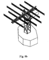
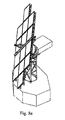
- An appropriately designed as a connection and / or construction device device is advantageously designed as a system of 2-point and / or 3-point and / or 4-point lattice trusses, as used in Mastbau (Glttermast), or stage construction (s. Fig. 8b ), flexible for the arrangement of, for example, plate-shaped elements (photovoltaic modules) at certain distances from each other or similar profile elements used.
- a further advantageous embodiment of the invention provides for the use of the device according to the invention as a presentation device for objects to be presented or advertising or electronic presentation elements, for example as a device for aligning screens or the like.
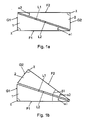
- the Fig. 1a and 1b show in a schematic side view of an apparatus for providing two functional surfaces F1 and F2, the position of which is mutually adjustable by rotation against each other.
- the functional surface F1 is arranged on the ground and the functional surface F2 forms the support surface or a support for the support surface.
- the device has two wedge elements 1 and 2 serving as wedge-shaped elements 1 and 2, whose bearing surface L1 or L2 and functional surface F1 or F2 converge at an acute angle ⁇ 1 or ⁇ 2, in the present case approximately 18o.
- the wedge-shaped elements 1 and 2 are presently designed as rectangular Kell comprise 1 and 2, wherein the angle between the angle ⁇ 1 or ⁇ 2 opposite side or side surface G1 or G2 and the jewelligen functional surface F1 or F2, in this case the angle ⁇ , 90 °.
- the wedge elements 1 and 2 are rotatably supported with their bearing surfaces in L1 and L2, wherein the bearing surfaces L1 and L2 of the wedge elements 1 and 2 face each other. Accordingly, the functional surfaces F1 and F2 of the Kell implant 1 and 2 facing away from each other.
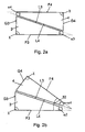
- Fig. 2a and 2b is a further embodiment of a device for providing functional surfaces F3 and F4, the position of which is adjustable to each other, shown.
- the functional surface F3 is arranged on the substrate and the functional surface F4 forms the support surface or a support for the support surface.
- the wedge-shaped elements 3 and 4 are presently formed as wedge stumps 3 and 4, wherein between the bearing surfaces L3 and L4 and the functional surfaces F3 and F4 of the wedge stumps 3 and 4 respectively the angle ⁇ 3 or ⁇ 4, in the present case about 18 °, is given.
- the position of the functional surface F4 of the truncated wedge 4 relative to the functional surface F3 of the truncated wedge 3 in the present case can be changed.
- the change in the position of the functional surface F4 relative to the functional surface F3 is effected by a change in the angle between the functional surface F3 and the functional surface F4, vorilegend the angle ⁇ 2 in Fig. 2b ,
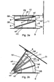
- FIG. 3a and 3b illustrated embodiment of an apparatus for providing two functional surfaces F5 and F8 are four wedge-shaped elements in the form of wedges 5, 6, 7 and 8, which are rotatably arranged, used.
- the functional surface F5 is arranged on the substrate 9 and the functional surface F8 forms a support for the support surface 10.
- the wedges 5 and 6 are presently formed at an angle ⁇ 5 and ⁇ 6 of about 18 °, while the trowel 7 and 8 an angle ⁇ 7 or have ⁇ 8 of about 9o.
- the functional surface F5 of the wedge 5 is in the present case rotatably mounted on the floor or a base surface 9.
- the functional surface F8 of the wedge 8 serves in the present case as a support for a support surface 10 mounted on a bearing 11.
- the device By twisting the wedges 6 and 8 relative to the wedges 5 and 7 respectively, the device is of the type described in US Pat Fig. 3a presented in the In Fig. 3b shown position can be brought, wherein between the functional surfaces F5 of the trowel 8 and the functional surface F8 of the wedge 8, the angle ⁇ 3 is taken.
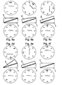
- Fig. 4a to 4f is shown in a schematic representation of the stepwise rotation of the wedge element 2 relative to the wedge element 1.
- the degree display shown above the wedge element 2 indicates the stepwise rotation of the wedge element 2.
- the specified below the wedge element 1 degree of rotation indicates the rotation of the wedge element 1 at.
- the Kell elements 1 is not twisted.
- Vorilegend a rotation of the Kell elements 2 starting from the in Fig. 4a Position shown by 360 ° In the in Fig. 4f shown position, corresponding to a full rotation of the wedge element 2.
- the wedge element 2 is rotated in each case by 45 ° clockwise relative to the wedge element 1.
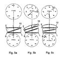
- Fig. 5a to 5c is a schematic, partially perspective schematic representation ( Fig. 5b and 6c ) shows the rotation of the wedge-shaped elements 1 and 2 of a further embodiment of a device according to the invention.
- the Fig. 5a to 5c show thereby the rotation of the wedge-shaped element 2 relative to the kellförmigen element 1 (of Fig. 5a to Fig. 5b ), with subsequent twisting (from Fig. 5b to Fig. 5c ) of both wedge-shaped elements 1 and 2 together with respect to the base.
- the device after the Fig. 5a to 5c has between the base 9 and the functional surface 1 of the wedge-shaped element 1, between the bearing surface 1 of the wedge-shaped element 1 and the bearing surface 2 of the wedge-shaped element 2, between the functional surface F2 of the wedge-shaped element 2 and the support surface 10 each pivot bearing.
- the relative position of the pivot bearing is selected so that the axis of rotation of the bearing between the base 9 and the functional surface 1 of the wedge-shaped element 1, the axis of rotation of the bearing between the bearing surface 1 of the wedge-shaped element 1 and the bearing surface 2 of the wedge-shaped element 2 and the axis of rotation of Bearing between the functional surface F2 of the wedge-shaped element 2 and the support surface 10 in this special case approximately at one point (pole, Drehpol) intersect the functional surface.
- the orientation of the 3-dimensionally dependent variable case (the arrow drawn on the support surface 10) whose magnitude and direction is clearly geometrically dependent on the relative displacement of the wedge-shaped element 2 with respect to the wedge-shaped element 1 is required when the direction of the line (the on the support surface 10 drawn arrow) should meet certain requirements, such as for tracking solar systems or as in a golf practice device, in which the skew of the stand on the function carrier against the direction of the golf ball can be aligned, eg in "hillside down” or “hillside up” or “lateral hillside up” or “lateral hillside up” or hybrid forms of said slopes, for example, an angle gauge, in which the 3-dimensional device change for a 2-dimensional Winkeidar ein or an angle projection a level (2-dimensional) is required.
- Fig. 5a to 5c illustrated embodiment is particularly advantageous available, especially since the point referred to above as the pole or Drehpol quasi resting for all possible movements.
- This point can advantageously be used in particular to devices in this Fix point on the functional surface, such as focusing devices, or target devices.
- the arrangement of the bearings is selected so that the point referred to above as pole or Drehpol definitely outside and / or above the functional level.
- This is particularly advantageous in the applications that require a dormant point above the functional level, for example, devices with resting as possible "focus” or targets (targets) targeted by laser, which then from different directions by operating the device with appropriately mounted Setup on the functional area, to this point (Pol, Drehpol) as a target, (target object) can aim.
- Applications are given for example in medical technology or energy technology. Due to the advantageously variably selectable arrangement of the pivot bearing can be prevented depending on the requirement in certain points of the device wobbling movements of the functional level or defined generated and / or performed.
- FIGS. 6d and 6e illustrated embodiment is particularly useful, in particular because the axis of rotation 201 of the upper Kellelements 202 approximately passes through the center of mass 203 of the entire upper functional unit 204, consisting of upper wedge element 202, the support structure 204a and the payload 204b, which are connected by connecting elements 211.
- Fig. 6d and 6e illustrated embodiment can be used particularly advantageous, especially since the point to be designated as the center of gravity or Drehpol point 203 undergoes no vertical displacement during all movements of the upper wedge member 202.
- This can advantageously be used in particular to minimize the drive power of the engine and to minimize the transmission in terms of the burden of own weight and payload.
- the particularly advantageous arrangement of the upperjanseinhelt 204 including payload 204b, such as photovoltaic modules, will be made with appropriate eccentricity 210 so that the geometric requirement that center of gravity 203 and axis of rotation 201 of the upper wedge member 202 meet in one point, with the inventive embodiment of the device according to Claim 1 is satisfied.
- the arrangement of the upper bearing 205 is arranged in the above embodiment according to claim 2 with such eccentricity 207 on the wedging plane that collisions with the lower wedge member 206 and the base 212 are avoided even with preferably 180 ° relative rotation of the upper Kellides 202 against the lower Kellelement 206 in that the functional plane 204 b additionally carries out a defined wobbling movement in addition to the desired banking of the inclined position without a substantial vertical movement of the center of mass 203 being established.
- the center of mass preferably moves in the device according to the invention on an approximately horizontal circular path by the common rotation of the two wedge elements 202 and 206 on the lower pivot bearing 208 about the axis of rotation 209th
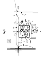
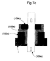
- the in the Fig. 7a to 7d shown embodiment of a device according to the invention comprises a mechanical Verstelleinhelt and structural design (II) for multiaxial angular or Drehwinkelverschlebungen, movements and / or changes with at least two angular elements, (wedge-shaped elements) or wedge-shaped constructions (hereinafter called angle elements, wedge elements or wedge discs) 101a and 101b, which are mutually rotatable or adjustable and / or stored or guided in the angle element or wedge element connection plane (wedge hinge connection plane) 102.
- a mechanical Verstelleinhelt and structural design II
- angle elements, wedge elements or wedge discs hereinafter called angle elements, wedge elements or wedge discs
- the Kellelbens 101a and 101b have fixed or freely adjustable Kellwinkel ⁇ 101a and ⁇ 101b.
- the relative rotational angle change ⁇ between the tiller arm 101a and the wedge disk 101b produces the change in the inclination angle ⁇ , that is, the inclination angle ⁇ is uniquely quantified by the relative rotational angle change ⁇ and the magnitude of the wallow angles ⁇ 101a and ⁇ 101b.
- the relative rotational angle change of the position angle ⁇ perpendicular to the functional plane which depends on the relative displacement ⁇ of the collision forces
- the falling falling line plane can be changed in any desired direction by the joint rotation angle change of the wedge disk 101a and the wedge disk 101b, preferably for example as in an angle gauge or by corresponding absolute rotation of the individual wedge shims 101a and 101b, which takes into account the desired angular position of the position angle ⁇ of the Failline.
- the base I has a suitable receptacle and / or bearing for the wedge element 101a, so that by adjusting the angle of rotation ⁇ of the wedge disks about the rotation axis 106 in addition to the adjustment of the inclination angle ⁇ and the orientation of the inclination angle ⁇ of the functional support level 104 to the desired position angle ⁇ can be achieved.
- the change of the angular position of the wedge elements to each other can be done manually or with one or more mechanical drives or by one or more preferably only stationary electrically operated drives.
- a stepless change of the multi-axial tilt angle can preferably be achieved with only a single drive unit.
- the device has operating devices or adjusting devices 107 and 111a and 111b for transmitting and changing the angular position of the Kellemia, which allow, driven by hand or with external energy, both targeted the relative movements of the wedge elements to each other, in particular the wedge disks 101a and 101b, and their gemelnsame To perform rotational movement or adjustment.
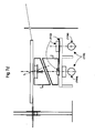
- the device further comprises a drive system (IV), which comprises at least one drive unit 109, with which the multiaxial angle or rotational angle displacements and movements and / or changes caused manually or by motor can be supported or selectively executed or prevented.
- a drive system (IV) which comprises at least one drive unit 109, with which the multiaxial angle or rotational angle displacements and movements and / or changes caused manually or by motor can be supported or selectively executed or prevented.
- the drive unit 109 preferably has at least one articulated shaft element 109b with which the multiaxial angular or rotational angle displacements and movements and / or changes of the wedge disk 101b caused manually or by motor can be supported or selectively executed and / or permitted or prevented.
- the shaft element 109b is preferably designed as a double shaft joint or as a propeller shaft as an articulated shaft element.
- the drive unit 109 is provided with devices 111 which transmit the actuating forces or the torque of the drive unit 109 to the wedge disks 101a and 101b.
- the device 111 is preferably embodied as a spoke ring 111a with spokes 111b, which transmit the actuating forces or the torque of the drive unit 109 to the splicebands 101a and 101b and from the wedge discs 101a and 101b to the drive unit 109.
- the drive unit 109 may additionally comprise at least one motor drive 110, as illustrated here.
- the motor drive 110 preferably has a single-stage or multistage geared motor (motor 110a with gear 110b.)
- the motor-driven drive 110 preferably has a single-stage or multistage worm geared motor, in the present case a twin-screw geared motor 110a, 110b, on the one hand to achieve low noise and, on the other hand, a high reduction ratio to be able to.
- the motor drive 110 may alternatively according to Fig. 7d a motor or a single or multi-stage geared motor 110a, and in addition a drive motor 112a with reduction stage 112, which may be implemented, for example with sprocket including drive chain or with a wedge or pulley including wedge or toothed belt.
- the drive unit 109 may additionally have a mechanical drive which acts as an extension of the drive shaft 109a as needed with an intermediate bevel gear or shaft joint, via which the manually or motor induced multiaxial angular or rotational angle shifts and movements and / or changes of the wedge disks 101a and 101b be supported or specifically executed or prevented.
- the device according to the invention has positively and / or non-positively cooperating elements with which the respective movements of the individual wedge discs to each other, as well as the movement of the wedge plate 101a on the base I, as well as the movement of the wedge plate 101 b relative to the functional support system (III) and also the movement of the function carrier system (III) relative to the stationary and / or the movable periphery (VI) can be prevented or blocked.
- the device according to the invention further comprises - as already explained a drive unit 109, in the gem.
- the positive and non-positive machine elements are integrated as a torque support and / or locking devices, preferably designed as a Frell runs or backstops 109c and 109d with a connecting element 109e.
- the drive unit 109 has for this purpose a torque arm or locking device or a positive and / or non-positive lock 109c, for example, Frel disruption, brakes, clutches, ratchets and / or the like locking devices or machine elements with rotation inhibiting and / or preventing effect, with the manually or motor-induced multiaxial angular or rotational angle shifts, movements and / or changes of at least one wedge disk 101a or 101b specifically supported, approved and / or can be prevented.
- the embodiment of the barrier 109c is preferably freewheeling, which selectively permits or prevents the relative rotation angle displacement and / or movement of the wedge disk 101a relative to the wedge disk 101b in a manner dependent on the direction of rotation.
- the drive unit 109 preferably has a further barrier 109d, which is preferably designed as a freewheeling system which selectively permits or prevents the rotation angle displacement and / or movement of the wedge disk 101a with respect to the base (I) in a direction dependent on the direction of rotation.
- the locks 109c and 109d as parts of the drive unit 109 are connected with each other by means of the connecting element 109e, with the drive unit 109 and with the base (I), so that by means of the idler pulleys 101a and 101b and the Antriebseinhelt 109 multiaxial rotation angle shifts and movements and the change in the inclination angle ⁇ or the inclination of the function carrier system (III) or - as vorllegend the inclination of the device on the choice of rotation on the one hand and by the respective rotation angle (+ ⁇ and - ⁇ ) preferably only a drive unit 109 can be brought about targeted or prevented00 can.
- the device has a rotation angle blocking system in the form of a torque support 107b, with which the target plane (functional support system III), that is the wing, can be held or guided relative to the periphery such that on the one hand there is up to 5-axis freedom of movement, on the other hand co-rotation of the target plane around the target axis in all oblique and angular and tilt positions is prevented.
- a rotation angle blocking system in the form of a torque support 107b, with which the target plane (functional support system III), that is the wing, can be held or guided relative to the periphery such that on the one hand there is up to 5-axis freedom of movement, on the other hand co-rotation of the target plane around the target axis in all oblique and angular and tilt positions is prevented.
- the device on the part of the function carrier system (III) also support surface, function carrier level, functional structure, target level, carrier level or head level called means on which fixed with the mechanical adjustment and / or the structural design (II), in particular with a wedge plate 101 b connected or advantageously movable or lockable connected to this or stored on this.
- These means of the functional support system (III) preferably comprise devices for positioning or fastening z.
- B of photovoltaic modules are preferably arranged or can be arranged centrally on the part of the functional support system (III).
- the functional support system (III) has a position angle element 131, which is preferably arranged connected to the toe plate 101b or the axis of rotation 106, the wedge disk axis 105 above the shaft joint 109b.
- the rotational angle position of the position angle element 131 represents the rotational angle position of the wedge discs relative to each other (relative displacement) in the Keilusionntagensebene 102, achievable or effected by rotation of the wedge disk axis 105, and thus the inclination angle ⁇ of the functional support level 104th
- the device according to the invention has, as a matter of principle, a mechanical angle position angle element 131, which also visually indicates the angle of elevation of the function carrier plane and / or has a corresponding rotary encoder function.
- the position angle element 131 preferably has a Anzelgefunktion the inclination angle ⁇ .
- the Position angle element 131 preferably has a rotary encoder function or functionality and is preferably designed such that it can be used as part of a rotary encoder system in order to detect the angle of inclination ⁇ .
- the device may comprise a controller (VII), ie a device for measuring, controlling and / or controlling the devices and / or devices of the golf training device according to the invention, which are the manually or motor induced multiaxial angle or rotational angle shifts, movements and / or changes switches, measures, regulates, controls or carries out the data or signal transmission and / or makes the motion event displayable via analogue or digital technology.
- the controller (VII) preferably comprises a banking position determining and / or transmitting system.
- the skew position determination and / or transmission system preferably comprises at least one rotary encoder or a position encoder system. This can be done both at the base (I), the mechanical adjustment unit (II), the functional support system (III), the drive system (IV).
- the rotary encoder of the encoder or position encoder system is preferably connected to the wedge element shaft 105 or the drive shaft 109a or the pivot bearings.
- the rotary encoder is preferably designed as a donor element for the relative rotational angle change ⁇ between the wedge disk 101a and the wedge disk 101b, which in the present case represents the change in the inclination angle ⁇ .
- the rotary encoder or the rotary encoder function can be used as an actual value encoder and preferably the actual values of the inclination angle ⁇ transmitted to an inclination angle actual value display,
- the encoder or position encoder system may have a rotary encoder or a rotary encoder function, preferably the registered change angle ⁇ of both wedge disks 101a and 101b, which represents the change of the rotational angle position or the change of the position angle ⁇ about the axis 106.
- the rotary encoder with rotary encoder function represents an actual value encoder function and preferably has an actual value transfer function of the position swing ⁇ for the transmission to the actual value display.
- the rotary encoder or rotary encoder functions preferably also have a donor function for the soil / actual value control or signal unit.
- the encoder or position encoder system has an actual value encoder function and / or an actual value transmission function for higher-level Control, data processing and / or for transfer purposes.
- the encoder or position sensor system further preferably has a network-connected or wireless signal transmission.
- the controller (VII) preferably has an engine control system.
- the engine control system has a network-attached or wireless signal transmission.
- the engine control system advantageously has a wireless, especially as a radio control or by infrared (IR) remote controlled signal transmission.
- the engine control system preferably has a radio control for signal transmission.
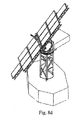
- Fig. 8a to 8h illustrated preferred embodiment in perspective view shows the Relatovverwarung of 0 °, 40 ", 80 °, 120 ° and 180 ° of the wedge-shaped elements of an embodiment of a device according to the invention for a tracking system for solar, antenna or radio equipment and a preferred embodiment of the support system in Fig. 8b with 2-point, 3-point and 4-point lattice trusses and lattice mast.
- Fig. 8g and 8h is the juxtaposition of the relative rotation 0 ° and 180 ° of the wedge-shaped elements corresponding to the starting position 0 ° degree oblique position and 90 ° inclined position in the embodiment of a device according to the invention, in which the effective wedge angle ⁇ 9 and ⁇ 10 are preferably 45 °.
- the angular accuracy is obtained by the wedge disk principle forced guidance of the tilting levels and increased by the jewellige choice of wedge element angle, since even small to maximum tilt angle always "enlarged” on the 180 ° scale of the rotation angle difference. be imaged between the wedge discs, so that can be realized with the wedge principle, among other things, precision angle teachings.
- Tilt angles can be represented by angles of rotation and simplify the metrological equipment.
- the operation for tracking and adjusting multi-axis turning or tilting angles generates only low noise levels and is characterized by the ability to dispense entirely with pneumatic or hydraulic drives and reduce the control effort for the drive system, characterized
- An advantage over the known devices for tracking solar, antenna or radio equipment is that the adjustability of the inclination of the wing of such functional units as preferably from 0 ° to 90 ° can be done to reduce weight and wind loads by adjustment and damage avoid.
Landscapes
- Engineering & Computer Science (AREA)
- Physics & Mathematics (AREA)
- Life Sciences & Earth Sciences (AREA)
- Sustainable Development (AREA)
- Sustainable Energy (AREA)
- Thermal Sciences (AREA)
- Chemical & Material Sciences (AREA)
- Combustion & Propulsion (AREA)
- Mechanical Engineering (AREA)
- General Engineering & Computer Science (AREA)
- Photovoltaic Devices (AREA)
- Support Of Aerials (AREA)
Applications Claiming Priority (1)
| Application Number | Priority Date | Filing Date | Title |
|---|---|---|---|
| DE102008018114A DE102008018114A1 (de) | 2008-04-09 | 2008-04-09 | Vorrichtung zur Bereitstellung von Funktionsflächen zur Einstellung von Solar-Antennen- und Funkanlagen |
Publications (2)
| Publication Number | Publication Date |
|---|---|
| EP2108901A2 true EP2108901A2 (fr) | 2009-10-14 |
| EP2108901A3 EP2108901A3 (fr) | 2012-03-14 |
Family
ID=40874478
Family Applications (1)
| Application Number | Title | Priority Date | Filing Date |
|---|---|---|---|
| EP09005081A Withdrawn EP2108901A3 (fr) | 2008-04-09 | 2009-04-07 | Dispositif de préparation de surfaces de fonctionnement, destiné au réglage d'installations solaires, d'antennes et/ou de radio |
Country Status (2)
| Country | Link |
|---|---|
| EP (1) | EP2108901A3 (fr) |
| DE (1) | DE102008018114A1 (fr) |
Cited By (2)
| Publication number | Priority date | Publication date | Assignee | Title |
|---|---|---|---|---|
| EP3176095A1 (fr) * | 2015-12-02 | 2017-06-07 | Thales | Structure deployable comportant un ensemble de generateurs solaires, systeme de deploiement d'une telle structure deployable et satellite comportant un tel systeme |
| CN115892484A (zh) * | 2022-11-24 | 2023-04-04 | 亿航智能设备(广州)有限公司 | 航空器动力组件 |
Families Citing this family (3)
| Publication number | Priority date | Publication date | Assignee | Title |
|---|---|---|---|---|
| DE102011105326A1 (de) * | 2011-06-03 | 2012-12-06 | Imo Holding Gmbh | Vorrichtung zur mehrachsigen Verstellung eines Anlagenteils |
| ES2674438R1 (es) * | 2016-12-28 | 2018-12-07 | Nabtesco Corporation | Helióstato y dispositivo de accionamiento para orientar un panel de un helióstato |
| DE102021006164A1 (de) | 2021-12-14 | 2023-06-15 | Kastriot Merlaku | Solarmodul-Nachführ-System |
Family Cites Families (6)
| Publication number | Priority date | Publication date | Assignee | Title |
|---|---|---|---|---|
| DE1225945B (de) * | 1962-02-20 | 1966-09-29 | Friedrich Wilhelm Deckel Dipl | Schwenkbarer Aufspanntisch fuer Werkstuecke |
| FR2486293B1 (fr) * | 1980-07-04 | 1986-11-21 | Europ Agence Spatiale | Nouveau dispositif d'orientation et de positionnement d'une charge utile |
| DE3244225A1 (de) * | 1982-11-30 | 1984-05-30 | Teldix Gmbh, 6900 Heidelberg | Anordnung zum positionieren von vorrichtungen wie antennen, solargeneratoren o.ae. |
| GB2188262A (en) * | 1986-03-25 | 1987-09-30 | Buckley & Taylor Limited | Universal manipulator for handling workpieces |
| DE102006002576A1 (de) * | 2006-01-18 | 2007-07-19 | Spiegel, Werner, Dipl. Ing. | Vorrichtung zur Bereitstellung von Funktionsflächen |
| DE102006002574A1 (de) * | 2006-01-18 | 2007-07-19 | Spiegel, Werner, Dipl. Ing. | Vorrrichtung zur Übung von Golfschlägen |
-
2008
- 2008-04-09 DE DE102008018114A patent/DE102008018114A1/de not_active Ceased
-
2009
- 2009-04-07 EP EP09005081A patent/EP2108901A3/fr not_active Withdrawn
Cited By (4)
| Publication number | Priority date | Publication date | Assignee | Title |
|---|---|---|---|---|
| EP3176095A1 (fr) * | 2015-12-02 | 2017-06-07 | Thales | Structure deployable comportant un ensemble de generateurs solaires, systeme de deploiement d'une telle structure deployable et satellite comportant un tel systeme |
| FR3044639A1 (fr) * | 2015-12-02 | 2017-06-09 | Thales Sa | Structure deployable comportant un ensemble de generateurs solaires, systeme de deploiement d'une telle structure deployable et satellite comportant un tel systeme |
| US10214302B2 (en) | 2015-12-02 | 2019-02-26 | Thales | Deployable structure comprising a set of solar generators, system for deploying such a deployable structure and satellite comprising such a system |
| CN115892484A (zh) * | 2022-11-24 | 2023-04-04 | 亿航智能设备(广州)有限公司 | 航空器动力组件 |
Also Published As
| Publication number | Publication date |
|---|---|
| DE102008018114A1 (de) | 2010-02-18 |
| EP2108901A3 (fr) | 2012-03-14 |
Similar Documents
| Publication | Publication Date | Title |
|---|---|---|
| EP3716471B1 (fr) | Entraînement à pivotement et déploiement pour panneaux solaires | |
| EP2108901A2 (fr) | Dispositif de préparation de surfaces de fonctionnement, destiné au réglage d'installations solaires, d'antennes et/ou de radio | |
| EP2619513A2 (fr) | Dispositif de reglage biaxial d'une installation, en particulier d'une unite de panneau solaire | |
| EP1691423A2 (fr) | Chassis pour supporter des modules solaires | |
| DE102005055258A1 (de) | Montierung für eine Gruppe von Solarmodulen | |
| DE102007051714A1 (de) | Photovoltaikanlage | |
| DE102009048855A1 (de) | Vorrichtung zur Positionierung von Solarsystemen | |
| EP2191129A2 (fr) | Dispositif de rotation | |
| DE202008013209U1 (de) | Baukastensystem eines Gestells für Solaranlagen | |
| DE102008050407A1 (de) | Baukastensystem eines Gestells für Solaranlagen | |
| DE202008015767U1 (de) | Nachführungseinrichtung für plattenförmige Solarmodule | |
| EP2754825A2 (fr) | Porte à tambour dotée d'une unité d'entraînement montée dans le sol | |
| DE202014000621U1 (de) | Zugfederkupplung zum Abbau windinduzierter Kräfte auf Solarnachführungen | |
| EP1973616A1 (fr) | Dispositif de formation de surfaces fonctionnelles pour exercices de golf | |
| WO2006131084A1 (fr) | Dispositif de creation d'un evenement | |
| DE102006002576A1 (de) | Vorrichtung zur Bereitstellung von Funktionsflächen | |
| WO2011110471A2 (fr) | Poursuite de surfaces solaires | |
| DE102008030747A1 (de) | Nachführeinrichtung | |
| EP0562428B1 (fr) | Manège avec une construction de fond raidement relevable | |
| EP1687673B1 (fr) | Tete de trepied a equilibrage de poids | |
| DE102008053039A1 (de) | Gleichgewichtstrainingsvorrichtung | |
| DE102006002574A1 (de) | Vorrrichtung zur Übung von Golfschlägen | |
| DE948950C (de) | Einfluegelwindmotor mit im wesentlichen vertikaler Drehachse | |
| DE102006022242A1 (de) | Verfahrsystem | |
| DE102019004468A1 (de) | Sonnennachführungsvorrichtung |
Legal Events
| Date | Code | Title | Description |
|---|---|---|---|
| PUAI | Public reference made under article 153(3) epc to a published international application that has entered the european phase |
Free format text: ORIGINAL CODE: 0009012 |
|
| AK | Designated contracting states |
Kind code of ref document: A2 Designated state(s): AT BE BG CH CY CZ DE DK EE ES FI FR GB GR HR HU IE IS IT LI LT LU LV MC MK MT NL NO PL PT RO SE SI SK TR |
|
| PUAL | Search report despatched |
Free format text: ORIGINAL CODE: 0009013 |
|
| AK | Designated contracting states |
Kind code of ref document: A3 Designated state(s): AT BE BG CH CY CZ DE DK EE ES FI FR GB GR HR HU IE IS IT LI LT LU LV MC MK MT NL NO PL PT RO SE SI SK TR |
|
| AX | Request for extension of the european patent |
Extension state: AL BA RS |
|
| RIC1 | Information provided on ipc code assigned before grant |
Ipc: F24J 2/54 20060101AFI20120206BHEP |
|
| STAA | Information on the status of an ep patent application or granted ep patent |
Free format text: STATUS: THE APPLICATION IS DEEMED TO BE WITHDRAWN |
|
| 18D | Application deemed to be withdrawn |
Effective date: 20120915 |