EP2108963A2 - Dispositif de détection d'une rotation d'un élément rotatif - Google Patents
Dispositif de détection d'une rotation d'un élément rotatif Download PDFInfo
- Publication number
- EP2108963A2 EP2108963A2 EP20090004825 EP09004825A EP2108963A2 EP 2108963 A2 EP2108963 A2 EP 2108963A2 EP 20090004825 EP20090004825 EP 20090004825 EP 09004825 A EP09004825 A EP 09004825A EP 2108963 A2 EP2108963 A2 EP 2108963A2
- Authority
- EP
- European Patent Office
- Prior art keywords
- receiver
- coil
- voltage signal
- coils
- arrangement according
- Prior art date
- Legal status (The legal status is an assumption and is not a legal conclusion. Google has not performed a legal analysis and makes no representation as to the accuracy of the status listed.)
- Granted
Links
- 238000000034 method Methods 0.000 claims abstract description 13
- 238000011156 evaluation Methods 0.000 claims description 51
- 239000003990 capacitor Substances 0.000 claims description 16
- 230000010355 oscillation Effects 0.000 claims description 10
- 238000001514 detection method Methods 0.000 claims description 8
- 230000005284 excitation Effects 0.000 claims description 6
- 230000001419 dependent effect Effects 0.000 claims description 4
- 238000007599 discharging Methods 0.000 claims description 2
- 238000010586 diagram Methods 0.000 description 11
- 230000008878 coupling Effects 0.000 description 7
- 238000010168 coupling process Methods 0.000 description 7
- 238000005859 coupling reaction Methods 0.000 description 7
- XLYOFNOQVPJJNP-UHFFFAOYSA-N water Substances O XLYOFNOQVPJJNP-UHFFFAOYSA-N 0.000 description 6
- 230000001939 inductive effect Effects 0.000 description 4
- 238000012545 processing Methods 0.000 description 4
- 230000001965 increasing effect Effects 0.000 description 3
- 230000009466 transformation Effects 0.000 description 3
- 239000004020 conductor Substances 0.000 description 2
- 238000013461 design Methods 0.000 description 2
- 238000005516 engineering process Methods 0.000 description 2
- 238000004519 manufacturing process Methods 0.000 description 2
- 238000005259 measurement Methods 0.000 description 2
- 238000012935 Averaging Methods 0.000 description 1
- 238000010521 absorption reaction Methods 0.000 description 1
- 230000006978 adaptation Effects 0.000 description 1
- 230000003321 amplification Effects 0.000 description 1
- 230000002238 attenuated effect Effects 0.000 description 1
- 230000005540 biological transmission Effects 0.000 description 1
- 238000004364 calculation method Methods 0.000 description 1
- 238000009833 condensation Methods 0.000 description 1
- 230000005494 condensation Effects 0.000 description 1
- 230000007423 decrease Effects 0.000 description 1
- 230000000994 depressogenic effect Effects 0.000 description 1
- 238000011161 development Methods 0.000 description 1
- 230000005611 electricity Effects 0.000 description 1
- 238000003199 nucleic acid amplification method Methods 0.000 description 1
- 239000000758 substrate Substances 0.000 description 1
- 238000004804 winding Methods 0.000 description 1
Images




Classifications
-
- G—PHYSICS
- G01—MEASURING; TESTING
- G01P—MEASURING LINEAR OR ANGULAR SPEED, ACCELERATION, DECELERATION, OR SHOCK; INDICATING PRESENCE, ABSENCE, OR DIRECTION, OF MOVEMENT
- G01P3/00—Measuring linear or angular speed; Measuring differences of linear or angular speeds
- G01P3/42—Devices characterised by the use of electric or magnetic means
- G01P3/44—Devices characterised by the use of electric or magnetic means for measuring angular speed
- G01P3/48—Devices characterised by the use of electric or magnetic means for measuring angular speed by measuring frequency of generated current or voltage
- G01P3/481—Devices characterised by the use of electric or magnetic means for measuring angular speed by measuring frequency of generated current or voltage of pulse signals
-
- G—PHYSICS
- G01—MEASURING; TESTING
- G01D—MEASURING NOT SPECIALLY ADAPTED FOR A SPECIFIC VARIABLE; ARRANGEMENTS FOR MEASURING TWO OR MORE VARIABLES NOT COVERED IN A SINGLE OTHER SUBCLASS; TARIFF METERING APPARATUS; MEASURING OR TESTING NOT OTHERWISE PROVIDED FOR
- G01D5/00—Mechanical means for transferring the output of a sensing member; Means for converting the output of a sensing member to another variable where the form or nature of the sensing member does not constrain the means for converting; Transducers not specially adapted for a specific variable
- G01D5/12—Mechanical means for transferring the output of a sensing member; Means for converting the output of a sensing member to another variable where the form or nature of the sensing member does not constrain the means for converting; Transducers not specially adapted for a specific variable using electric or magnetic means
- G01D5/14—Mechanical means for transferring the output of a sensing member; Means for converting the output of a sensing member to another variable where the form or nature of the sensing member does not constrain the means for converting; Transducers not specially adapted for a specific variable using electric or magnetic means influencing the magnitude of a current or voltage
- G01D5/20—Mechanical means for transferring the output of a sensing member; Means for converting the output of a sensing member to another variable where the form or nature of the sensing member does not constrain the means for converting; Transducers not specially adapted for a specific variable using electric or magnetic means influencing the magnitude of a current or voltage by varying inductance, e.g. by a movable armature
- G01D5/204—Mechanical means for transferring the output of a sensing member; Means for converting the output of a sensing member to another variable where the form or nature of the sensing member does not constrain the means for converting; Transducers not specially adapted for a specific variable using electric or magnetic means influencing the magnitude of a current or voltage by varying inductance, e.g. by a movable armature by influencing the mutual induction between two or more coils
- G01D5/2053—Mechanical means for transferring the output of a sensing member; Means for converting the output of a sensing member to another variable where the form or nature of the sensing member does not constrain the means for converting; Transducers not specially adapted for a specific variable using electric or magnetic means influencing the magnitude of a current or voltage by varying inductance, e.g. by a movable armature by influencing the mutual induction between two or more coils by a movable non-ferromagnetic conductive element
-
- G—PHYSICS
- G01—MEASURING; TESTING
- G01P—MEASURING LINEAR OR ANGULAR SPEED, ACCELERATION, DECELERATION, OR SHOCK; INDICATING PRESENCE, ABSENCE, OR DIRECTION, OF MOVEMENT
- G01P13/00—Indicating or recording presence, absence, or direction, of movement
- G01P13/02—Indicating direction only, e.g. by weather vane
- G01P13/04—Indicating positive or negative direction of a linear movement or clockwise or anti-clockwise direction of a rotational movement
-
- G—PHYSICS
- G01—MEASURING; TESTING
- G01P—MEASURING LINEAR OR ANGULAR SPEED, ACCELERATION, DECELERATION, OR SHOCK; INDICATING PRESENCE, ABSENCE, OR DIRECTION, OF MOVEMENT
- G01P3/00—Measuring linear or angular speed; Measuring differences of linear or angular speeds
- G01P3/42—Devices characterised by the use of electric or magnetic means
- G01P3/44—Devices characterised by the use of electric or magnetic means for measuring angular speed
- G01P3/48—Devices characterised by the use of electric or magnetic means for measuring angular speed by measuring frequency of generated current or voltage
- G01P3/481—Devices characterised by the use of electric or magnetic means for measuring angular speed by measuring frequency of generated current or voltage of pulse signals
- G01P3/488—Devices characterised by the use of electric or magnetic means for measuring angular speed by measuring frequency of generated current or voltage of pulse signals delivered by variable reluctance detectors
-
- G—PHYSICS
- G01—MEASURING; TESTING
- G01P—MEASURING LINEAR OR ANGULAR SPEED, ACCELERATION, DECELERATION, OR SHOCK; INDICATING PRESENCE, ABSENCE, OR DIRECTION, OF MOVEMENT
- G01P3/00—Measuring linear or angular speed; Measuring differences of linear or angular speeds
- G01P3/42—Devices characterised by the use of electric or magnetic means
- G01P3/44—Devices characterised by the use of electric or magnetic means for measuring angular speed
- G01P3/48—Devices characterised by the use of electric or magnetic means for measuring angular speed by measuring frequency of generated current or voltage
- G01P3/481—Devices characterised by the use of electric or magnetic means for measuring angular speed by measuring frequency of generated current or voltage of pulse signals
- G01P3/489—Digital circuits therefor
Definitions
- the invention relates to an arrangement for detecting a rotation of a rotary member.
- a common problem in consumer measurement technology is to electronically scan the rotational movement of a rotary element rotating at a consumption-proportional speed.
- Such consumption meters are found for example in water, heat; Gas and electricity meters.
- an electrical signal is generated, which is further processed by evaluation, to then represent the calculated consumption via a display system or to supply a billing system.
- a particular challenge is that the arrangement against temperature, moisture, dirt and electric and magnetic DC and AC fields as well as DC and alternating light should be insensitive, on the one hand to maintain the functionality of the arrangement and on the other hand, to exclude external manipulation. It can also happen that the consumption meter has to adjust to a maximum consumption detection in a very short period of time from a longer standstill.
- the power consumption for the arrangement should be as low as possible in order to ensure the operation of the consumption meter by means of a battery for at least one calibration period, which extends over a period of several years.
- an arrangement for detecting a rotation of a rotary member which comprises a rotary member having an electrically conductive partial surface and at least two electrodes, of which at least one serves as an excitation electrode and at least one as a receiving electrode, and the capacitive on rotation of the rotary member via the electrically conductive partial surface are coupled.
- the excitation electrode is supplied with voltage pulses, and at the receiver electrode receiver signals are tapped.
- DE 10 2005 054 342 A1 discloses an arrangement for detecting a rotation of a rotary element in which an excitation electrode and receiver electrodes are capacitively coupled via a rotary element, the rotary element having an electrically conductive partial surface, whereby the receiver signals of the receiver electrodes are modulated upon rotation of the rotary element.
- the high resistance of the capacitive sensing causes easy interference by medium and high-frequency interference fields.
- the capacitive sensing is disturbed by the presence of water, which is due to the high dielectric constant of the water. Therefore, direct capacitive sensing of an impeller in water is impossible. But even with other consumption measurements, condensation can disturb the capacitive sensing.
- DE 35 19 215 C2 discloses a sensor for converting a mechanical input into an electrical output, wherein a respective donor coil and receiver coil coupled to a resonant circuit is provided, and wherein the donor coil and receiver coil are substantially perpendicular to each other.
- the DE 39 23 398 C1 describes a rotation detector in which a rotor is capacitively coupled to a plurality of resonant circuits, resonances generated in the resonant circuits for revolution determination being evaluated.
- the invention is thus based on the object of specifying an arrangement for detecting a rotation of a rotary element, which is insensitive to external interference and easy to implement and thereby has a low power consumption.
- the invention it is therefore provided to inductively detect the rotation detection of the rotary element by an inductive coupling between at least one transmitter coil and at least one receiver coil, which is modulated by the rotational position of the rotary element.
- inductive coupling With inductive coupling, the transmission of energy between two coils is described by a common magnetic field, which can be realized even in low-voltage operation. Therefore, the inventive arrangement for detecting the rotation of a rotary element is insensitive to interference by water, whereby the rotating element can also be used in this. Due to the pulsed energization of the encoder coil low power consumption is realized.
- a current pulse can consist of a single pulse, a group of individual pulses or a damped oscillation.
- a current pulse is a current that exists only within a limited time. He is paused. If the pauses between the current pulses are of equal duration, these are individual pulses. A group of individual pulses is accordingly the repeated presence of the current with pauses between them, one group being separated from the next by a longer pause than the individual pulses of a group.
- a group of single pulses is also called a burst.
- Such a burst can also be generated when an alternating voltage is applied and then without pauses between the periods of the oscillation, this being called the alternating voltage burst.
- the sensor device may preferably have two, three or four receiver coils which are arranged substantially coplanar and in a planar manner and which are arranged substantially offset by 90 ° relative to one another.
- two receiver coils which are equally spaced from the encoder coil and arranged offset by 90 ° to each other, not only the full rotation of the rotary member can be detected, but also the direction of rotation.
- the sensor device has two mutually opposite receiver coils and a relative to these two offset by 90 ° each receiver coil.
- This then third receiver coil can be used to adjust the first receiver coil by the respective receiver voltage signals are compared or differential voltage is formed.
- tolerances or variations can be compensated by component tolerances, operating voltage or temperature changes.
- this calibration concept can also be transferred to the second receiver coil.
- these are distributed symmetrically around the encoder coil.
- the evaluation means may comprise at least one multiplexer, wherein the at least one multiplexer, the parallel incident receiver voltage signals of the receiver coils by repeated current pulse excitation of Encoder coil converts into a single serial receiver voltage signal.
- the at least one multiplexer any use of a multiplexer several energizations of the encoder coil are required, the time interval must be small compared to the Abtastzeitabstand so that the rotary element has rotated only minimally further between them and therefore the receiver voltage signals have changed only minimally between the two energys.
- an analog multiplexer it is possible to reduce the burden of evaluation means.
- the receiver voltage signals can then run on a single line and accordingly fall the required evaluation only once and not four times as in the case of four receiver coils.
- the receiver voltage signals from in each case two, preferably opposing, receiver coils can be combined by a multiplexer into a single serial receiver voltage signal.
- the signals can be subtracted from one another in the course of the further evaluation in order to obtain a differential voltage signal, but an averaging is also conceivable.
- each two receiver voltage signals are given to a multiplexer and converted into a serial signal, which can then be further processed.
- the evaluation means may comprise at least one transistor circuit, with which the receiver voltage signal given to this can be amplified.
- the number of transistor circuits depends firstly on the number of receiver coils and secondly on the use of one or more multiplexers.
- each receiver coil may be followed by a transistor circuit, however, when using a multiplexer, it makes sense to arrange the transistor circuit after this multiplexer and thus to amplify the serial receiver voltage signal, whereby the number of transistor circuits to be used can be reduced.
- Be four receiver voltage signals each two opposite each other Coils are combined by two multiplexers, accordingly, two transistor circuits are required, a single multiplexer is used to summarize the receiver voltage signals of all coils, so also satisfies a single transistor circuit.
- the considerations made here regarding the transistor circuit apply analogously also for the components used in the further evaluation.
- the evaluation means may comprise at least one maximum detector with a storage capacitor for storing the maximum receiver voltage signal.
- the receiver voltage signals are comparatively small and short, in particular the duration of a pulsed signal is approximately 50 ns.
- a transistor circuit can be used, while a maximum detector with a storage capacitor allows an extension of the pulse duration. This step is not absolutely necessary, but it can be used in the further processing chain cheaper and power-saving components, as it would not be possible without a maximum detector.
- the evaluation means may comprise a discharge resistor for discharging the storage capacitor until reaching a threshold voltage, wherein the discharge time serves as a measure of the height of the maximum receiver voltage signal.
- the evaluation means comprise an A / D converter for digitizing the maximum receiver voltage signal. For reading out the stored in the storage capacitor of the maximum detector maximum receiver voltage signal so there are several options available. Even when using a maximum detector with corresponding devices asserted again the above statements regarding the number depending on the receiver coils used and one or more multiplexers. If a discharge resistor is used to determine the maximum receiver voltage signal, the discharge time serving as a measure of the height of the maximum receiver voltage signal can also be easily digitized. Basically, it can therefore be assumed that the receiver voltage signal, whether it is serial or not, after passing of the maximum detector and the devices calculated in digital form, but an analogue further processing of the signals is not excluded.
- the evaluation means may comprise at least one comparator.
- the comparator is used to compare two variables and outputs an output result depending on the input variables.
- Comparators may be both analog and digital, and the output may be either a logic value, a difference value, the larger of the two inputs, or any other value.
- each receiver coil may be followed by a comparator, to which the respective receiver voltage signals are gebbar.
- this embodiment is conceivable if each receiver coil is individually followed by separate evaluation means; on the other hand, the receiver voltage signals converted by a multiplexer into a serial signal can also be split again into individual signals and in each case transferred separately to a comparator.
- the differential voltage signal of the receiver voltage signals of two, preferably opposing, receiver coils can be gebbar to a comparator.
- the coils may be connected in series according to their sense of winding so that the total voltage results as the differential voltage of the receiver voltage pulses of the two coils. It is also possible to compare a serial receiver voltage signal with a single comparator.
- the same threshold can be assigned to each comparator.
- the comparator requires in addition to the input signal in the form of a receiver voltage signal and a reference signal with which the input signal is compared.
- voltages are compared with one another at a comparator; therefore, in addition to an input voltage, a comparison voltage is also required. Therefore, to keep the structure simple, the same threshold can always be used.
- the thresholds associated with the comparators for comparing the receiver voltage signals may be adjustable to different values. Due to device tolerances it may be necessary to separately set the threshold for each receiver voltage signal, on the other hand, due to operating voltage or temperature changes, the adaptability of the thresholds during operation may also be necessary. In these cases, the adjustability of the individual threshold values should be kept as variable as possible in order to be able to react to the corresponding requirements.
- the threshold value for the differential voltage signal of the receiver voltage signals of two mutually opposite receiver coils may be dependent on the mean value of the receiver voltage signals.
- the differential voltage signal for example, temperature changes can be compensated for, while the dependence of the threshold value on the average value of the receiver voltage signals compensates for component tolerances.
- the receiver voltage signals from two, preferably opposite, receiver coils may be comparable on a comparator.
- no reference voltage or reference value is needed, but the voltages of two receiver coils are directly compared. This procedure can only be carried out in the case of at least three receiver coils.
- the conductive portion may be realized in the form of a conductor loop having a first loop portion located below the encoder coil and having a second loop portion located in the radial direction closer to the edge of the rotary member and below the one or more Receiver coils is movable.
- This arrangement realizes a double pulse transformer, wherein the donor coil and the first loop portion and the second loop portion and the receiver coil or receiver coils optionally above are magnetically coupled together, and the first and the second coil portion electrically to each other are connected. Since the rotary member can rotate, the same receiver coils are not always located over the second loop portion, which for this purpose does not fully cover the rotary member.
- the modulation of the receiver voltage signals can be amplified, and the signal difference between the receiver voltage signals of two coils, one over an electrically conductive portion of the rotary member and the other over an electrically non-conductive portion of the rotary member, can be increased.
- At least one coil can be realized as a printed circuit board coil.
- the multilayer PCB technology enables small PCB coils in the range up to a few ⁇ H.
- Such PCB coils ensure on the one hand minimum manufacturing tolerances, on the other hand, they allow a ferrite-free design of the coils.
- all coils are designed as depressed coils on a common substrate.
- the invention also relates to a method for detecting revolutions of a rotating and at least partially electrically conductive rotary member by means of a sensor device comprising at least one encoder coil, at least one receiver coil, means for pulsed energization of the encoder coil and evaluation, wherein the coils are formed flat and coplanar side by side when energized in at least one donor coil generates a pulsed magnetic field through which the donor coil and the at least one receiver coil are inductively coupled and through which in the at least one receiver coil a modulated depending on the rotational position of the rotary element, pulsed receiver voltage signal is generated by the evaluation is evaluated.
- a single receiver coil half of the rotation of the rotary element can be detected by evaluating the receiver voltage signal.
- the number of half revolutions can be determined, but taking into account the time to complete a full revolution can also be the angular velocity of the rotary member or the flow velocity of the medium whose flow volume is to be determined.
- the current pulse used in the method according to the invention can likewise consist of a single pulse, a group of individual pulses or a damped oscillation.
- a sensor device may be used having two receiver coils which are preferably equidistant from the encoder coil and substantially offset by ninety degrees from one another and which provide separate receiver voltage signals from which information describing the direction of rotation of the rotary element is determined. Only the use of a second coil thus allows the detection of the direction of rotation, but at the same time can be improved by the use of the second coil, the angular resolution of the revolution count of half revolutions to quarter turns.
- a sensor device can be used with a third receiver coil, which are offset substantially by 90 ° to each other and provide separate receiver voltage signals, wherein based on a comparison or a difference of the receiver voltage signals from two, preferably two opposing receiver coils, a compensation of any receiver voltage signal fluctuations.
- a third receiver coil which are offset substantially by 90 ° to each other and provide separate receiver voltage signals, wherein based on a comparison or a difference of the receiver voltage signals from two, preferably two opposing receiver coils, a compensation of any receiver voltage signal fluctuations.
- a sensor device can be used with a fourth receiver coil, which are offset substantially by 90 ° to each other and provide separate receiver voltage signals, wherein based on a comparison, a difference in the receiver voltage signals in each case two opposing receiver coils compensation of any receiver voltage signal fluctuations.
- the fully symmetrical arrangement of four receiver coils around the encoder coil allows tolerance-minimum and cost-optimal rotation detection and Störssennelimination. optimally, works such a coil array preferably low impedance and inductive, that is magnetic instead of electrical, which is why the process is not affected by any existing water and electrical interference.
- a battery-powered implementation of the method can be ensured over years, wherein the frequency of the current supply can be made dependent on the determined rotational speed.
- the pulse rate should be at least four times, in particular six to eight times the revolution frequency. Since such arrangements for detecting the rotational speed of the rotary element may stand still for years until the process according to the invention is carried out again by renewed consumption absorption, an adaptation of the clock frequency of the energization of the transmitter coil is expedient in order to save energy.
- a first loop section may be arranged on the rotary element, which is located below the encoder coil, and on the rotary element, a second loop section is arranged, which is arranged in the radial direction closer to the edge of the rotary member and is moved below the one or more receiver coils, wherein the loop sections are electrically connected to one another and, when the transmitter coil is energized in the first loop section, a current pulse is generated by magnetic coupling which is converted into a magnetic field pulse in the second loop section, thereby increasing the height of the receiver voltage signal in the receiver coils located above the second conductor loop.
- the parallel generated receiver voltage signals may be applied to at least one multiplexer which converts the receiver voltage signals into a single serial receiver voltage signal.
- the receiver voltage signals from each two, preferably opposing, receiver coils can be combined by a multiplexer into a single serial receiver voltage signal.
- the at least one receiver voltage signal can be applied to at least one transistor circuit with which the receiver voltage signal given to it is amplified.
- the at least one receiver voltage signal may be applied to at least one maximum detector having a storage capacitor for storing the maximum voltage value of the receiver coil signal of a receiver coil.
- the at least one receiver voltage signal can be applied to at least one half-wave integrator with a storage capacitor for storing the voltage value of the receiver coil signal of a receiver coil.
- the storage capacitor can be discharged via a discharge resistor until reaching a threshold voltage, wherein the discharge time is used as a measure of the height of the maximum receiver coil signal.
- the maximum receiver coil signal can be digitized by an A / D converter.
- the at least one receiver voltage signal can be applied to at least one comparator.
- each receiver coil may be followed by a comparator, to which the respective receiver voltage signals are applied.
- the differential voltage signal of the receiver voltage signals of two opposing receiver coils may be applied to a comparator.
- the same threshold can be assigned to each comparator.
- the thresholds associated with the comparators may be set to different values.
- the threshold value for the differential voltage signal of the receiver voltage signals of two mutually opposite receiver coils may depend on the mean value of the receiver voltage signals.
- the threshold value for the receiver voltage signal of one receiver coil may depend on the level of the receiver voltage signal of another receiver coil.
- the receiver voltage signals of two opposing receiver coils can be compared on a comparator.
- Fig. 1 Not shown is the line of the medium and the medium whose consumption is to be detected by the rotary member 1 and the sensor device 2.
- the rotary member 1 has a cylindrical or disc shape, wherein Fig. 1 shows the cross section of the cylinder or the disc, while the sensor device 2 is shown only schematically. Not shown are the devices of the rotary member 1, which cause the rotation. These are known in particular in the form of an impeller to those skilled in the art.
- the disc or cylinder so the rotary member 1, sits on z. B. the impeller and is rotated.
- the arrangement of the devices of the sensor device 2 can Fig. 2 be removed.
- the coil array formed from the coils is arranged such that the centrally arranged encoder coil 3 is surrounded by the four receiver coils 4, 5, 6 and 7 symmetrically and offset by 90 ° in each case.
- the receiver coils 4, 5, 6 and 7 each evaluation means 21 are connected downstream. However, the evaluation means 21 are explicitly drawn only for receiver coil 4.
- the encoder coil 3 is connected to the energizing means 8 and a supply voltage 9, while the energizing means 8 and the evaluation means 21 are each again connected to a control unit 22. While in the evaluation means 21 most different configurations can be realized, which are the donor coil Downstream means 36, which consist of Bestromungsstoff 8 and supply voltage 9, always provide.
- FIGS. 3A-C show various possible variations of the rotary member 1, wherein in each case an electrically conductive portion 11 and an electrically non-conductive portion 10 are given.
- a semicircular conductive portion 11 is shown in FIG Fig. 3B the semicircular portion 11 additionally has a semicircular section, so that the donor coil located above it is completely occupied.
- the electrically conductive section 11 short-circuit currents are induced by the magnetic field pulse, which generate an opposing field, are displaced by the sum of donor field and opposing field up and to the side, whereby the coupling between the donor and receiver coil also varies depending on the angle of rotation.
- Such a partially conductive rotary element 1 is easy to manufacture and therefore inexpensive.
- FIG. 3C An embodiment which enables a double pulse transformation is shown Fig. 3C ,
- the first loop 13 and the second loop 14 of the loop assembly 12 are electrically interconnected with the donor coil 3 disposed above the first loop 13 and one or more of the receiver coils 4, 5, 6 and 7 over the second loop 14.
- the linear configuration of the second loop 14 and its limitation to half the circumference of the rotary element 1 there are always two receiver coils over the second loop 14. Since the rotary element 1 rotates, in each case other receiver coils 4, 5, 6 or 7 lie above the second section 14 during the execution of the procedure.
- the area over the second loop 14 can be regarded as an electrically conductive portion 11, while the area not covered by the loop arrangement 12 is formed as an electrically non-conductive portion 10.
- a current pulse is generated in the first loop 13 by magnetic coupling, which is converted in the second loop 14 into a magnetic field pulse, which is increased in the receiver coil over the second loop 14, the height of the receiver voltage signal, which is a double pulse transformation equate to.
- the second loop 14 may be provided, which may be formed in particular semicircular and displaces the field of the donor coil by circulating currents induced in it. Depending on the geometry of Coils and rotating element thereby increases or decreases the second loop 14 at received receiver coils over the received voltage pulse.
- Fig. 4 shows receiver coil 4 with downstream evaluation means 21 in a first embodiment.
- the receiver voltage signal of the receiver coil 4 is thereby applied to a transistor circuit 15, whereby the receiver voltage signal is amplified.
- a maximum detector 37 with a storage capacitor 16 and a discharge resistor 17, whereby the maximum value of the receiver voltage signal can be determined.
- This maximum value is then compared at a comparator 20 with a threshold value, wherein the resistors 18 and 19 are still required as a voltage divider of the supply voltage 9, so that the comparison voltage applied to the comparator in each case is smaller than the charge voltage present at the storage capacitor 16. Since the maximum value has not been digitized, an analog comparison with a supply voltage 9 takes place at the comparator 20.
- the output signal returned by the comparator is then forwarded to the control unit 22.
- FIG. 5 An alternative way of signal processing after the maximum detector 37 is shown Fig. 5 . After the receiver voltage signal of the receiver coil 7 has been applied to the maximum detector 37, it is digitized by the A / D converter 38 and then passed to the control unit 22.
- the use of at least two receiver coils 4 and 7 also allows the determination of the direction of rotation of the rotary element 1, which in Fig. 6 is shown.
- a comparator 20 with resistors 18 and 19 is connected downstream, while for the evaluation of the receiver voltage signal of the receiver coil 7, the supply voltage 23, the resistors 24 and 25 and the comparator 26 is present.
- the comparators 20 and 26 respectively output signals 27 and 28 whose timing is represented by the curves 29 and 30.
- the time is indicated, while on the y-axes 32 and 41, the output from the respective comparator signal intensity is shown as a curve 29 and 30, respectively.
- the axis sections 33 and 34 indicate the respective output values of the curves 29 and 30.
- the value of the receiver voltage signal of the receiver coil 4 represented by curve 29 changes earlier from the value designated as intercept 34 as the value of the curve 30 and also returns earlier to this value.
- the time difference between the curves is shown as ⁇ t. From the time that elapses until curve 29 has again reached approximately the value of the axis section 34, the angular velocity of the rotary element 1 can be calculated, and from the position of the changes of the curve 29 and 30 to each other, the direction of rotation can be determined.
- a multiplexer 35 may be provided.
- the receiver voltage signals of the receiver coils 4 and 7 are converted by the multiplexer 35 into a serial receiver voltage signal which is applied to the comparator 20.
- the comparator 20 can be acted upon with different supply voltages 9 in order to assign a separate comparison value to each receiver voltage signal. If possible, however, the same supply voltage 9 is applied and thus also the same threshold value is used for all the receiver voltage signals.
- the output signal of the comparator 20 is applied to the control unit 22, which in turn controls the multiplexer 35 again.
- This digitized, serial receiver voltage signal of the receiver coils 4 and 7 is applied to the controller 22, which controls the A / D converter 37, the multiplexer 35 and the means 36 based on the received signals.
- the receiver voltage signal of the receiver coil 7 is compared at the comparator 20 with a value which is predetermined by the control device 22.
- the signal of the control device 22 is converted by a D / A converter 39 into an analog signal, wherein the signal and thus the height of the comparison voltage applied to the comparator 20 can be freely selected by the control device 22.
- Fig. 10 One way to combine the receiver voltage signals of two opposing receiver coils 5 and 7 shows Fig. 10 , The coils are connected in series according to their Windungsraum such that the comparator 20, the differential voltage signal of the two receiver coils 5 and 7 is applied. As a result, only the sign of the differential voltage signal is then evaluated. For simplicity, only two coils are shown here, the same arrangement with two offset by 90 ° receiver coils 4 and 6 with corresponding evaluation means 21 is still necessary for detecting the direction of rotation. By using the differential voltage, variations in the receiver voltage signal caused by temperature changes or the like can be eliminated. By using common evaluation means, which can also include amplifiers and maximum value detector, all offset and drift errors of these circuit elements are excluded from the evaluation.
- the receiver voltage signals of the receiver coils 5 and 7 may alternatively be applied to one input of the comparator 20, respectively, and then the receiver voltage signals of the receiver coils 5 and 7 are directly compared with each other. This automatically eliminates the dependence on absolute pulse heights. The sign of the differential voltage signal then decides which of the two mutually opposite receiver coils receives a larger voltage pulse due to the modulation by the rotary element.
- the comparator 20 can be used as Output value return a logic signal, for example, as a value 1 that the receiver voltage signal of the receiver coil 5 is greater than that of the receiver coil 7, while in the opposite case, a 0 is returned.
- the number of coils used is not limited to the number of coils shown in the figures, but is optimally assumed by four receiver coils. Only for the sake of clarity, the number of coils shown in the figures and the subsequent evaluation means has been reduced.
- the number of individual evaluation means depends on the presence of a multiplexer and also on the circuit of the receiver coils. If an analog multiplexer is used to combine all the receiver voltage signals, all offset and drift errors of the downstream evaluation means such as amplifiers, maximum value detector and comparator will drop out of the rotation detection. Accordingly, these evaluation means are also needed only once. The digitization of the signal can already take place after the maximum detector, but it can also be provided that the comparator connected downstream of a maximum detector is given an analog signal which is digitized only after the comparator.
- the usual quadrature logic can be used in at least two receiver coils. If more than two coils are used, the signals of two opposing coils are combined to form a logic signal, and then again perform the calculation with the usual quadrature logic.
- Fig. 12 shows an embodiment of the means 36 for acting on the encoder coil, with the application of a damped vibrations is possible.
- a capacitor 42 and a switch 43 are provided.
- the means 36 are controlled via the control unit 22.
- the advantage of this embodiment of the means 36 is that only the excitation energy is extracted for a single pulse of the battery, but the resulting induced receiver voltage signal consists of many pulses of the attenuated resonant circuit.
- the voltage waveform of the pulse generation according to this embodiment of the means 36 is shown in FIG Fig. 13 shown.
- the time t is plotted, while the axis 46 represents a measure of the voltage U.
- the curve of the voltage curve begins with the value 47 of the supply voltage, wherein the amplitude decays over time.
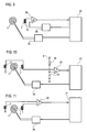
- Fig. 14 a circuit comprising a half-wave integrator 52 having a storage capacitor 16 and a diode 48. Due to the rectifier function of the diode only one half-wave of the receiver voltage signal is transmitted, so in each case the positive or negative half periods. These unipolar half periods are added up by the storage capacitor 16.
- the discharge resistor 17 simultaneously discharges the capacitor 16, causing the receiver voltage signal between two AC bursts or damped oscillations to slowly drop back to zero. The addition of the half-waves results in a larger overall useful signal.
- Fig. 15 shows an alternative embodiment of the arrangement of the diode 48, wherein depending on the configuration of the diode 48 according to Fig. 14 or according to Fig. 15 then each positive or negative half-waves are allowed to pass.
- the time course of the not yet summed receiver voltage signal of the half-wave integrator 52 is in Fig. 16 shown.
- the axis 49 represents time t and axis 50 represents the receiver voltage signal.
- the curve 51 thus shows the time profile of the receiver voltage signal.
- Fig. 17 shows a schematic diagram of two receiver coils with downstream evaluation means, wherein the encoder coil 3 is applied to an AC voltage burst or a damped oscillation periodically.
- the multiplexer 35 converts the receiver voltage signals of the receiver coils 4 and 7 into a single serial receiver voltage signal. This is applied to the half-wave integrator 52. In the half-wave integrator 52, the serial receiver voltage signal is added in a unipolar manner, with the receiver voltage signals of the individual receiver coils being added up separately. Thereafter, the receiver voltage signal is applied to a comparator 20.
- the function of the other components is as described for the previous figures.
Landscapes
- Physics & Mathematics (AREA)
- General Physics & Mathematics (AREA)
- Transmission And Conversion Of Sensor Element Output (AREA)
Applications Claiming Priority (1)
| Application Number | Priority Date | Filing Date | Title |
|---|---|---|---|
| DE200810018099 DE102008018099A1 (de) | 2008-04-09 | 2008-04-09 | Anordnung zum Erfassen einer Drehung eines Drehelements |
Publications (3)
| Publication Number | Publication Date |
|---|---|
| EP2108963A2 true EP2108963A2 (fr) | 2009-10-14 |
| EP2108963A3 EP2108963A3 (fr) | 2011-05-25 |
| EP2108963B1 EP2108963B1 (fr) | 2014-09-24 |
Family
ID=40873422
Family Applications (1)
| Application Number | Title | Priority Date | Filing Date |
|---|---|---|---|
| EP20090004825 Not-in-force EP2108963B1 (fr) | 2008-04-09 | 2009-04-01 | Dispositif de détection d'une rotation d'un élément rotatif |
Country Status (2)
| Country | Link |
|---|---|
| EP (1) | EP2108963B1 (fr) |
| DE (1) | DE102008018099A1 (fr) |
Cited By (3)
| Publication number | Priority date | Publication date | Assignee | Title |
|---|---|---|---|---|
| EP2881745A1 (fr) * | 2013-12-06 | 2015-06-10 | Rosemount Aerospace Inc. | Capteurs inductifs de vitesse de rotation |
| CN108279027A (zh) * | 2018-02-08 | 2018-07-13 | 江苏昕泉物联科技有限公司 | 抗强磁干扰的无磁转动信号采集装置 |
| CN109443462A (zh) * | 2018-12-07 | 2019-03-08 | 杭州为峰智能科技有限公司 | 一种防磁计量检测装置 |
Families Citing this family (1)
| Publication number | Priority date | Publication date | Assignee | Title |
|---|---|---|---|---|
| DE102010018271B4 (de) | 2010-04-26 | 2012-12-20 | Prof. Dr. Horst Ziegler & Partner GbR (vertretungsberechtigter Gesellschafter: Dipl.-Ing. F. W. Ziegler, 70499 Stuttgart) | Technik zur Erfassung einer Drehbewegung |
Citations (7)
| Publication number | Priority date | Publication date | Assignee | Title |
|---|---|---|---|---|
| EP0121734A1 (fr) | 1983-03-21 | 1984-10-17 | Socam | Dispositif de mesure de la rotation d'une turbine de compteurs de débit de fluide |
| DE3519215C2 (fr) | 1985-04-13 | 1989-06-15 | Ziegler, Horst, Prof. Dipl.-Phys. Dr., 4790 Paderborn, De | |
| DE3923398C1 (fr) | 1989-07-14 | 1991-01-03 | Ziegler, Horst, Prof. Dr., 4790 Paderborn, De | |
| US6043644A (en) | 1996-04-29 | 2000-03-28 | Cesm Centre Suisse D'electronique Et De Microtechnique Sa - Recherche Et Developpement | Device for detecting position and movement by using magnetic field variation |
| EP1033578A2 (fr) | 1999-02-27 | 2000-09-06 | Horst Prof. Dr. Ziegler | Dispositif de détermination de la rotation d'un élément rotatif |
| DE102005054342A1 (de) | 2005-11-11 | 2007-05-31 | Prof. Dr. Horst Ziegler und Partner GbR (vertretungsberechtigter Gesellschafter: Prof. Dr. Horst Ziegler 33100 Paderborn) | Anordnung zum Detektieren einer Rotation eines Drehelements |
| US20080164869A1 (en) | 2005-03-07 | 2008-07-10 | Sappel | Inductive Angular-Position Sensor |
Family Cites Families (6)
| Publication number | Priority date | Publication date | Assignee | Title |
|---|---|---|---|---|
| US3286200A (en) * | 1964-02-18 | 1966-11-15 | Orson G Foulger | Pulse-amplitude to pulse-duration converter apparatus |
| JPS5651674A (en) * | 1979-10-03 | 1981-05-09 | Victor Co Of Japan Ltd | Level detecting circuit |
| US4425511A (en) * | 1981-02-09 | 1984-01-10 | Amnon Brosh | Planar coil apparatus employing a stationary and a movable board |
| GB9720954D0 (en) * | 1997-10-02 | 1997-12-03 | Scient Generics Ltd | Commutators for motors |
| DE19813497C2 (de) * | 1998-03-26 | 2000-11-16 | Vogt Electronic Ag | Induktiver Weggeber |
| WO2007054592A1 (fr) * | 2005-11-08 | 2007-05-18 | Zertan, S.A. | Systeme d'elimination de perturbations destine a des capteurs inductifs |
-
2008
- 2008-04-09 DE DE200810018099 patent/DE102008018099A1/de not_active Withdrawn
-
2009
- 2009-04-01 EP EP20090004825 patent/EP2108963B1/fr not_active Not-in-force
Patent Citations (7)
| Publication number | Priority date | Publication date | Assignee | Title |
|---|---|---|---|---|
| EP0121734A1 (fr) | 1983-03-21 | 1984-10-17 | Socam | Dispositif de mesure de la rotation d'une turbine de compteurs de débit de fluide |
| DE3519215C2 (fr) | 1985-04-13 | 1989-06-15 | Ziegler, Horst, Prof. Dipl.-Phys. Dr., 4790 Paderborn, De | |
| DE3923398C1 (fr) | 1989-07-14 | 1991-01-03 | Ziegler, Horst, Prof. Dr., 4790 Paderborn, De | |
| US6043644A (en) | 1996-04-29 | 2000-03-28 | Cesm Centre Suisse D'electronique Et De Microtechnique Sa - Recherche Et Developpement | Device for detecting position and movement by using magnetic field variation |
| EP1033578A2 (fr) | 1999-02-27 | 2000-09-06 | Horst Prof. Dr. Ziegler | Dispositif de détermination de la rotation d'un élément rotatif |
| US20080164869A1 (en) | 2005-03-07 | 2008-07-10 | Sappel | Inductive Angular-Position Sensor |
| DE102005054342A1 (de) | 2005-11-11 | 2007-05-31 | Prof. Dr. Horst Ziegler und Partner GbR (vertretungsberechtigter Gesellschafter: Prof. Dr. Horst Ziegler 33100 Paderborn) | Anordnung zum Detektieren einer Rotation eines Drehelements |
Cited By (5)
| Publication number | Priority date | Publication date | Assignee | Title |
|---|---|---|---|---|
| EP2881745A1 (fr) * | 2013-12-06 | 2015-06-10 | Rosemount Aerospace Inc. | Capteurs inductifs de vitesse de rotation |
| US9285386B2 (en) | 2013-12-06 | 2016-03-15 | Rosemount Aerospace Inc. | Inductive rotational speed sensors |
| CN108279027A (zh) * | 2018-02-08 | 2018-07-13 | 江苏昕泉物联科技有限公司 | 抗强磁干扰的无磁转动信号采集装置 |
| CN109443462A (zh) * | 2018-12-07 | 2019-03-08 | 杭州为峰智能科技有限公司 | 一种防磁计量检测装置 |
| CN109443462B (zh) * | 2018-12-07 | 2024-05-10 | 杭州为峰智能科技有限公司 | 一种防磁计量检测装置 |
Also Published As
| Publication number | Publication date |
|---|---|
| EP2108963B1 (fr) | 2014-09-24 |
| EP2108963A3 (fr) | 2011-05-25 |
| DE102008018099A1 (de) | 2009-11-05 |
Similar Documents
| Publication | Publication Date | Title |
|---|---|---|
| EP2105713B1 (fr) | Appareil de mesure de position et son procédé de fonctionnement | |
| DE60216263T2 (de) | Positionsdetektor | |
| DE68907628T2 (de) | Elektromagnetischer durchflussmesser zur gleichzeitigen messung des durchflusses und der leitfaehigkeit einer fluessigkeit. | |
| EP2567223B1 (fr) | Dispositif de mesure de la conductibilité électrique d'un milieu liquide | |
| EP2666023B1 (fr) | Appareil de mesure de courant | |
| EP2108843B1 (fr) | Capteur destiné à allumer et/ou éteindre une pompe | |
| DE69532630T2 (de) | Magnetisch-induktiver Durchflussmesser | |
| DE2656111C3 (de) | Wirbelstromprüfgerät | |
| CH694996A5 (de) | Verfahren zu Ueberpruefen eines elektromagnetischen Durchflussmessers und elektromagnetische Durchflussmesseranordnung. | |
| AT509101A1 (de) | Induktive messeinrichtung für längen- und winkelerfassung | |
| EP2651043B1 (fr) | Dispositif et procédé de transmission d'énergie et de données entre une unité de commande et un appareil de mesure de position | |
| DE4447295A1 (de) | Verfahren und Vorrichtung zur Bestimmung einer jeweiligen örtlichen Position eines Körpers durch kapazitive Abtastung | |
| WO2014060330A1 (fr) | Procédé et dispositif de mesure d'un courant circulant dans un interrupteur | |
| EP2108963B1 (fr) | Dispositif de détection d'une rotation d'un élément rotatif | |
| DE102011015589B3 (de) | Anordnung und Verfahren zur kapazitiven Abtastung der Drehbwegung eines Drehelements | |
| EP2642663A1 (fr) | Capteur et procédé destinés à la vérification d'un objet | |
| DE102017128472B4 (de) | Induktiver Näherungsschalter und Verfahren zum Betreiben eines induktiven Näherungsschalters | |
| WO2016041726A1 (fr) | Dispositif et procédé permettant de surveiller une grandeur de processus d'un milieu | |
| WO2006040267A1 (fr) | Procede et dispositif de determination de l'ecart entre une surface profilee et une surface fonctionnelle mobile par rapport a celle-ci au moyen de deux bobines de mesure | |
| DE102017128471B4 (de) | Induktiver Näherungsschalter und Verfahren zum Betreiben eines induktiven Näherungsschalters | |
| DE102011111041A1 (de) | Sensoranordnung zur kontaktlosen Ermittlung der aktuellen Winkelstellung einer Welle | |
| EP2381223B1 (fr) | Technique de détection d'un mouvement de rotation | |
| EP3345302B1 (fr) | Commutateur de proximité inductif comprenant un microcontrôleur | |
| DE102008064544B4 (de) | Positions-/Wegmesssystem und Verfahren zur Bestimmung der Position eines Gebers | |
| CH667535A5 (de) | Verfahren zum messen eines magnetfeldes und einrichtung zur ausfuehrung des verfahrens. |
Legal Events
| Date | Code | Title | Description |
|---|---|---|---|
| PUAI | Public reference made under article 153(3) epc to a published international application that has entered the european phase |
Free format text: ORIGINAL CODE: 0009012 |
|
| AK | Designated contracting states |
Kind code of ref document: A2 Designated state(s): AT BE BG CH CY CZ DE DK EE ES FI FR GB GR HR HU IE IS IT LI LT LU LV MC MK MT NL NO PL PT RO SE SI SK TR |
|
| RIC1 | Information provided on ipc code assigned before grant |
Ipc: G01P 13/04 20060101ALI20100813BHEP Ipc: G01P 3/481 20060101AFI20090728BHEP Ipc: G01P 3/489 20060101ALI20100813BHEP Ipc: G01D 5/20 20060101ALI20100813BHEP |
|
| PUAL | Search report despatched |
Free format text: ORIGINAL CODE: 0009013 |
|
| AK | Designated contracting states |
Kind code of ref document: A3 Designated state(s): AT BE BG CH CY CZ DE DK EE ES FI FR GB GR HR HU IE IS IT LI LT LU LV MC MK MT NL NO PL PT RO SE SI SK TR |
|
| AX | Request for extension of the european patent |
Extension state: AL BA RS |
|
| 17P | Request for examination filed |
Effective date: 20110827 |
|
| GRAP | Despatch of communication of intention to grant a patent |
Free format text: ORIGINAL CODE: EPIDOSNIGR1 |
|
| INTG | Intention to grant announced |
Effective date: 20140417 |
|
| GRAP | Despatch of communication of intention to grant a patent |
Free format text: ORIGINAL CODE: EPIDOSNIGR1 |
|
| INTG | Intention to grant announced |
Effective date: 20140708 |
|
| GRAS | Grant fee paid |
Free format text: ORIGINAL CODE: EPIDOSNIGR3 |
|
| GRAA | (expected) grant |
Free format text: ORIGINAL CODE: 0009210 |
|
| AK | Designated contracting states |
Kind code of ref document: B1 Designated state(s): AT BE BG CH CY CZ DE DK EE ES FI FR GB GR HR HU IE IS IT LI LT LU LV MC MK MT NL NO PL PT RO SE SI SK TR |
|
| REG | Reference to a national code |
Ref country code: GB Ref legal event code: FG4D Free format text: NOT ENGLISH |
|
| REG | Reference to a national code |
Ref country code: CH Ref legal event code: EP |
|
| REG | Reference to a national code |
Ref country code: AT Ref legal event code: REF Ref document number: 688849 Country of ref document: AT Kind code of ref document: T Effective date: 20141015 |
|
| REG | Reference to a national code |
Ref country code: IE Ref legal event code: FG4D Free format text: LANGUAGE OF EP DOCUMENT: GERMAN |
|
| REG | Reference to a national code |
Ref country code: DE Ref legal event code: R096 Ref document number: 502009009994 Country of ref document: DE Effective date: 20141106 |
|
| PG25 | Lapsed in a contracting state [announced via postgrant information from national office to epo] |
Ref country code: NO Free format text: LAPSE BECAUSE OF FAILURE TO SUBMIT A TRANSLATION OF THE DESCRIPTION OR TO PAY THE FEE WITHIN THE PRESCRIBED TIME-LIMIT Effective date: 20141224 Ref country code: FI Free format text: LAPSE BECAUSE OF FAILURE TO SUBMIT A TRANSLATION OF THE DESCRIPTION OR TO PAY THE FEE WITHIN THE PRESCRIBED TIME-LIMIT Effective date: 20140924 Ref country code: GR Free format text: LAPSE BECAUSE OF FAILURE TO SUBMIT A TRANSLATION OF THE DESCRIPTION OR TO PAY THE FEE WITHIN THE PRESCRIBED TIME-LIMIT Effective date: 20141225 Ref country code: SE Free format text: LAPSE BECAUSE OF FAILURE TO SUBMIT A TRANSLATION OF THE DESCRIPTION OR TO PAY THE FEE WITHIN THE PRESCRIBED TIME-LIMIT Effective date: 20140924 Ref country code: LT Free format text: LAPSE BECAUSE OF FAILURE TO SUBMIT A TRANSLATION OF THE DESCRIPTION OR TO PAY THE FEE WITHIN THE PRESCRIBED TIME-LIMIT Effective date: 20140924 |
|
| REG | Reference to a national code |
Ref country code: LT Ref legal event code: MG4D Ref country code: NL Ref legal event code: VDEP Effective date: 20140924 |
|
| PG25 | Lapsed in a contracting state [announced via postgrant information from national office to epo] |
Ref country code: LV Free format text: LAPSE BECAUSE OF FAILURE TO SUBMIT A TRANSLATION OF THE DESCRIPTION OR TO PAY THE FEE WITHIN THE PRESCRIBED TIME-LIMIT Effective date: 20140924 Ref country code: HR Free format text: LAPSE BECAUSE OF FAILURE TO SUBMIT A TRANSLATION OF THE DESCRIPTION OR TO PAY THE FEE WITHIN THE PRESCRIBED TIME-LIMIT Effective date: 20140924 Ref country code: CY Free format text: LAPSE BECAUSE OF FAILURE TO SUBMIT A TRANSLATION OF THE DESCRIPTION OR TO PAY THE FEE WITHIN THE PRESCRIBED TIME-LIMIT Effective date: 20140924 |
|
| PG25 | Lapsed in a contracting state [announced via postgrant information from national office to epo] |
Ref country code: NL Free format text: LAPSE BECAUSE OF FAILURE TO SUBMIT A TRANSLATION OF THE DESCRIPTION OR TO PAY THE FEE WITHIN THE PRESCRIBED TIME-LIMIT Effective date: 20140924 |
|
| PG25 | Lapsed in a contracting state [announced via postgrant information from national office to epo] |
Ref country code: SK Free format text: LAPSE BECAUSE OF FAILURE TO SUBMIT A TRANSLATION OF THE DESCRIPTION OR TO PAY THE FEE WITHIN THE PRESCRIBED TIME-LIMIT Effective date: 20140924 Ref country code: EE Free format text: LAPSE BECAUSE OF FAILURE TO SUBMIT A TRANSLATION OF THE DESCRIPTION OR TO PAY THE FEE WITHIN THE PRESCRIBED TIME-LIMIT Effective date: 20140924 Ref country code: RO Free format text: LAPSE BECAUSE OF FAILURE TO SUBMIT A TRANSLATION OF THE DESCRIPTION OR TO PAY THE FEE WITHIN THE PRESCRIBED TIME-LIMIT Effective date: 20140924 Ref country code: IS Free format text: LAPSE BECAUSE OF FAILURE TO SUBMIT A TRANSLATION OF THE DESCRIPTION OR TO PAY THE FEE WITHIN THE PRESCRIBED TIME-LIMIT Effective date: 20150124 Ref country code: PT Free format text: LAPSE BECAUSE OF FAILURE TO SUBMIT A TRANSLATION OF THE DESCRIPTION OR TO PAY THE FEE WITHIN THE PRESCRIBED TIME-LIMIT Effective date: 20150126 Ref country code: CZ Free format text: LAPSE BECAUSE OF FAILURE TO SUBMIT A TRANSLATION OF THE DESCRIPTION OR TO PAY THE FEE WITHIN THE PRESCRIBED TIME-LIMIT Effective date: 20140924 Ref country code: ES Free format text: LAPSE BECAUSE OF FAILURE TO SUBMIT A TRANSLATION OF THE DESCRIPTION OR TO PAY THE FEE WITHIN THE PRESCRIBED TIME-LIMIT Effective date: 20140924 |
|
| PG25 | Lapsed in a contracting state [announced via postgrant information from national office to epo] |
Ref country code: PL Free format text: LAPSE BECAUSE OF FAILURE TO SUBMIT A TRANSLATION OF THE DESCRIPTION OR TO PAY THE FEE WITHIN THE PRESCRIBED TIME-LIMIT Effective date: 20140924 |
|
| REG | Reference to a national code |
Ref country code: DE Ref legal event code: R097 Ref document number: 502009009994 Country of ref document: DE |
|
| PG25 | Lapsed in a contracting state [announced via postgrant information from national office to epo] |
Ref country code: DK Free format text: LAPSE BECAUSE OF FAILURE TO SUBMIT A TRANSLATION OF THE DESCRIPTION OR TO PAY THE FEE WITHIN THE PRESCRIBED TIME-LIMIT Effective date: 20140924 |
|
| PLBE | No opposition filed within time limit |
Free format text: ORIGINAL CODE: 0009261 |
|
| STAA | Information on the status of an ep patent application or granted ep patent |
Free format text: STATUS: NO OPPOSITION FILED WITHIN TIME LIMIT |
|
| PG25 | Lapsed in a contracting state [announced via postgrant information from national office to epo] |
Ref country code: IT Free format text: LAPSE BECAUSE OF FAILURE TO SUBMIT A TRANSLATION OF THE DESCRIPTION OR TO PAY THE FEE WITHIN THE PRESCRIBED TIME-LIMIT Effective date: 20140924 |
|
| 26N | No opposition filed |
Effective date: 20150625 |
|
| PG25 | Lapsed in a contracting state [announced via postgrant information from national office to epo] |
Ref country code: LU Free format text: LAPSE BECAUSE OF FAILURE TO SUBMIT A TRANSLATION OF THE DESCRIPTION OR TO PAY THE FEE WITHIN THE PRESCRIBED TIME-LIMIT Effective date: 20150401 Ref country code: MC Free format text: LAPSE BECAUSE OF FAILURE TO SUBMIT A TRANSLATION OF THE DESCRIPTION OR TO PAY THE FEE WITHIN THE PRESCRIBED TIME-LIMIT Effective date: 20140924 |
|
| GBPC | Gb: european patent ceased through non-payment of renewal fee |
Effective date: 20150401 |
|
| REG | Reference to a national code |
Ref country code: IE Ref legal event code: MM4A |
|
| PG25 | Lapsed in a contracting state [announced via postgrant information from national office to epo] |
Ref country code: GB Free format text: LAPSE BECAUSE OF NON-PAYMENT OF DUE FEES Effective date: 20150401 |
|
| PG25 | Lapsed in a contracting state [announced via postgrant information from national office to epo] |
Ref country code: SI Free format text: LAPSE BECAUSE OF FAILURE TO SUBMIT A TRANSLATION OF THE DESCRIPTION OR TO PAY THE FEE WITHIN THE PRESCRIBED TIME-LIMIT Effective date: 20140924 |
|
| REG | Reference to a national code |
Ref country code: FR Ref legal event code: PLFP Year of fee payment: 8 |
|
| PG25 | Lapsed in a contracting state [announced via postgrant information from national office to epo] |
Ref country code: IE Free format text: LAPSE BECAUSE OF NON-PAYMENT OF DUE FEES Effective date: 20150401 |
|
| PG25 | Lapsed in a contracting state [announced via postgrant information from national office to epo] |
Ref country code: MT Free format text: LAPSE BECAUSE OF FAILURE TO SUBMIT A TRANSLATION OF THE DESCRIPTION OR TO PAY THE FEE WITHIN THE PRESCRIBED TIME-LIMIT Effective date: 20140924 |
|
| REG | Reference to a national code |
Ref country code: FR Ref legal event code: PLFP Year of fee payment: 9 |
|
| PG25 | Lapsed in a contracting state [announced via postgrant information from national office to epo] |
Ref country code: BG Free format text: LAPSE BECAUSE OF FAILURE TO SUBMIT A TRANSLATION OF THE DESCRIPTION OR TO PAY THE FEE WITHIN THE PRESCRIBED TIME-LIMIT Effective date: 20140924 Ref country code: HU Free format text: LAPSE BECAUSE OF FAILURE TO SUBMIT A TRANSLATION OF THE DESCRIPTION OR TO PAY THE FEE WITHIN THE PRESCRIBED TIME-LIMIT; INVALID AB INITIO Effective date: 20090401 |
|
| PG25 | Lapsed in a contracting state [announced via postgrant information from national office to epo] |
Ref country code: BE Free format text: LAPSE BECAUSE OF NON-PAYMENT OF DUE FEES Effective date: 20150430 |
|
| PG25 | Lapsed in a contracting state [announced via postgrant information from national office to epo] |
Ref country code: TR Free format text: LAPSE BECAUSE OF FAILURE TO SUBMIT A TRANSLATION OF THE DESCRIPTION OR TO PAY THE FEE WITHIN THE PRESCRIBED TIME-LIMIT Effective date: 20140924 |
|
| REG | Reference to a national code |
Ref country code: FR Ref legal event code: PLFP Year of fee payment: 10 |
|
| PG25 | Lapsed in a contracting state [announced via postgrant information from national office to epo] |
Ref country code: MK Free format text: LAPSE BECAUSE OF FAILURE TO SUBMIT A TRANSLATION OF THE DESCRIPTION OR TO PAY THE FEE WITHIN THE PRESCRIBED TIME-LIMIT Effective date: 20140924 |
|
| PGFP | Annual fee paid to national office [announced via postgrant information from national office to epo] |
Ref country code: FR Payment date: 20200421 Year of fee payment: 12 Ref country code: CH Payment date: 20200423 Year of fee payment: 12 Ref country code: DE Payment date: 20200409 Year of fee payment: 12 |
|
| PGFP | Annual fee paid to national office [announced via postgrant information from national office to epo] |
Ref country code: AT Payment date: 20200421 Year of fee payment: 12 |
|
| REG | Reference to a national code |
Ref country code: DE Ref legal event code: R119 Ref document number: 502009009994 Country of ref document: DE |
|
| REG | Reference to a national code |
Ref country code: AT Ref legal event code: MM01 Ref document number: 688849 Country of ref document: AT Kind code of ref document: T Effective date: 20210401 |
|
| PG25 | Lapsed in a contracting state [announced via postgrant information from national office to epo] |
Ref country code: DE Free format text: LAPSE BECAUSE OF NON-PAYMENT OF DUE FEES Effective date: 20211103 Ref country code: FR Free format text: LAPSE BECAUSE OF NON-PAYMENT OF DUE FEES Effective date: 20210430 Ref country code: AT Free format text: LAPSE BECAUSE OF NON-PAYMENT OF DUE FEES Effective date: 20210401 Ref country code: CH Free format text: LAPSE BECAUSE OF NON-PAYMENT OF DUE FEES Effective date: 20210430 Ref country code: LI Free format text: LAPSE BECAUSE OF NON-PAYMENT OF DUE FEES Effective date: 20210430 |