EP2109172A1 - Elektrolytmembran - Google Patents
Elektrolytmembran Download PDFInfo
- Publication number
- EP2109172A1 EP2109172A1 EP07860409A EP07860409A EP2109172A1 EP 2109172 A1 EP2109172 A1 EP 2109172A1 EP 07860409 A EP07860409 A EP 07860409A EP 07860409 A EP07860409 A EP 07860409A EP 2109172 A1 EP2109172 A1 EP 2109172A1
- Authority
- EP
- European Patent Office
- Prior art keywords
- electrolyte membrane
- sulfonic acid
- acid group
- membrane
- ion
- Prior art date
- Legal status (The legal status is an assumption and is not a legal conclusion. Google has not performed a legal analysis and makes no representation as to the accuracy of the status listed.)
- Withdrawn
Links
Images

Classifications
-
- H—ELECTRICITY
- H01—ELECTRIC ELEMENTS
- H01B—CABLES; CONDUCTORS; INSULATORS; SELECTION OF MATERIALS FOR THEIR CONDUCTIVE, INSULATING OR DIELECTRIC PROPERTIES
- H01B1/00—Conductors or conductive bodies characterised by the conductive materials; Selection of materials as conductors
- H01B1/06—Conductors or conductive bodies characterised by the conductive materials; Selection of materials as conductors mainly consisting of other non-metallic substances
- H01B1/12—Conductors or conductive bodies characterised by the conductive materials; Selection of materials as conductors mainly consisting of other non-metallic substances organic substances
- H01B1/122—Ionic conductors
-
- H—ELECTRICITY
- H01—ELECTRIC ELEMENTS
- H01M—PROCESSES OR MEANS, e.g. BATTERIES, FOR THE DIRECT CONVERSION OF CHEMICAL ENERGY INTO ELECTRICAL ENERGY
- H01M8/00—Fuel cells; Manufacture thereof
- H01M8/10—Fuel cells with solid electrolytes
-
- H—ELECTRICITY
- H01—ELECTRIC ELEMENTS
- H01B—CABLES; CONDUCTORS; INSULATORS; SELECTION OF MATERIALS FOR THEIR CONDUCTIVE, INSULATING OR DIELECTRIC PROPERTIES
- H01B1/00—Conductors or conductive bodies characterised by the conductive materials; Selection of materials as conductors
- H01B1/06—Conductors or conductive bodies characterised by the conductive materials; Selection of materials as conductors mainly consisting of other non-metallic substances
-
- H—ELECTRICITY
- H01—ELECTRIC ELEMENTS
- H01M—PROCESSES OR MEANS, e.g. BATTERIES, FOR THE DIRECT CONVERSION OF CHEMICAL ENERGY INTO ELECTRICAL ENERGY
- H01M8/00—Fuel cells; Manufacture thereof
- H01M8/02—Details
-
- H—ELECTRICITY
- H01—ELECTRIC ELEMENTS
- H01M—PROCESSES OR MEANS, e.g. BATTERIES, FOR THE DIRECT CONVERSION OF CHEMICAL ENERGY INTO ELECTRICAL ENERGY
- H01M8/00—Fuel cells; Manufacture thereof
- H01M8/02—Details
- H01M8/0289—Means for holding the electrolyte
-
- H—ELECTRICITY
- H01—ELECTRIC ELEMENTS
- H01M—PROCESSES OR MEANS, e.g. BATTERIES, FOR THE DIRECT CONVERSION OF CHEMICAL ENERGY INTO ELECTRICAL ENERGY
- H01M8/00—Fuel cells; Manufacture thereof
- H01M8/10—Fuel cells with solid electrolytes
- H01M8/1016—Fuel cells with solid electrolytes characterised by the electrolyte material
- H01M8/1018—Polymeric electrolyte materials
- H01M8/102—Polymeric electrolyte materials characterised by the chemical structure of the main chain of the ion-conducting polymer
- H01M8/1023—Polymeric electrolyte materials characterised by the chemical structure of the main chain of the ion-conducting polymer having only carbon, e.g. polyarylenes, polystyrenes or polybutadiene-styrenes
-
- H—ELECTRICITY
- H01—ELECTRIC ELEMENTS
- H01M—PROCESSES OR MEANS, e.g. BATTERIES, FOR THE DIRECT CONVERSION OF CHEMICAL ENERGY INTO ELECTRICAL ENERGY
- H01M8/00—Fuel cells; Manufacture thereof
- H01M8/10—Fuel cells with solid electrolytes
- H01M8/1016—Fuel cells with solid electrolytes characterised by the electrolyte material
- H01M8/1018—Polymeric electrolyte materials
- H01M8/1039—Polymeric electrolyte materials halogenated, e.g. sulfonated polyvinylidene fluorides
-
- H—ELECTRICITY
- H01—ELECTRIC ELEMENTS
- H01M—PROCESSES OR MEANS, e.g. BATTERIES, FOR THE DIRECT CONVERSION OF CHEMICAL ENERGY INTO ELECTRICAL ENERGY
- H01M8/00—Fuel cells; Manufacture thereof
- H01M8/10—Fuel cells with solid electrolytes
- H01M8/1016—Fuel cells with solid electrolytes characterised by the electrolyte material
- H01M8/1018—Polymeric electrolyte materials
- H01M8/1067—Polymeric electrolyte materials characterised by their physical properties, e.g. porosity, ionic conductivity or thickness
-
- H—ELECTRICITY
- H01—ELECTRIC ELEMENTS
- H01M—PROCESSES OR MEANS, e.g. BATTERIES, FOR THE DIRECT CONVERSION OF CHEMICAL ENERGY INTO ELECTRICAL ENERGY
- H01M2300/00—Electrolytes
- H01M2300/0017—Non-aqueous electrolytes
- H01M2300/0065—Solid electrolytes
- H01M2300/0082—Organic polymers
-
- H—ELECTRICITY
- H01—ELECTRIC ELEMENTS
- H01M—PROCESSES OR MEANS, e.g. BATTERIES, FOR THE DIRECT CONVERSION OF CHEMICAL ENERGY INTO ELECTRICAL ENERGY
- H01M2300/00—Electrolytes
- H01M2300/0088—Composites
- H01M2300/0094—Composites in the form of layered products, e.g. coatings
-
- Y—GENERAL TAGGING OF NEW TECHNOLOGICAL DEVELOPMENTS; GENERAL TAGGING OF CROSS-SECTIONAL TECHNOLOGIES SPANNING OVER SEVERAL SECTIONS OF THE IPC; TECHNICAL SUBJECTS COVERED BY FORMER USPC CROSS-REFERENCE ART COLLECTIONS [XRACs] AND DIGESTS
- Y02—TECHNOLOGIES OR APPLICATIONS FOR MITIGATION OR ADAPTATION AGAINST CLIMATE CHANGE
- Y02E—REDUCTION OF GREENHOUSE GAS [GHG] EMISSIONS, RELATED TO ENERGY GENERATION, TRANSMISSION OR DISTRIBUTION
- Y02E60/00—Enabling technologies; Technologies with a potential or indirect contribution to GHG emissions mitigation
- Y02E60/30—Hydrogen technology
- Y02E60/50—Fuel cells
-
- Y—GENERAL TAGGING OF NEW TECHNOLOGICAL DEVELOPMENTS; GENERAL TAGGING OF CROSS-SECTIONAL TECHNOLOGIES SPANNING OVER SEVERAL SECTIONS OF THE IPC; TECHNICAL SUBJECTS COVERED BY FORMER USPC CROSS-REFERENCE ART COLLECTIONS [XRACs] AND DIGESTS
- Y02—TECHNOLOGIES OR APPLICATIONS FOR MITIGATION OR ADAPTATION AGAINST CLIMATE CHANGE
- Y02P—CLIMATE CHANGE MITIGATION TECHNOLOGIES IN THE PRODUCTION OR PROCESSING OF GOODS
- Y02P70/00—Climate change mitigation technologies in the production process for final industrial or consumer products
- Y02P70/50—Manufacturing or production processes characterised by the final manufactured product
Definitions
- the present invention relates to an electrolyte membrane including a graft polymer having sulfonic acid group as a proton conductive group, and more particularly relates to an electrolyte membrane different in sulfonic acid group content in a thickness direction.
- a solid polymer electrolyte fuel cell has been expected to be used in wide fields such as a domestic co-generation power source, a power source for mobile instruments, a power source for electric automobiles and a simple auxiliary power source, because of its high energy density.
- an electrolyte membrane functions as an electrolyte for conducting protons, and simultaneously plays a role of a diaphragm for preventing hydrogen or methanol which is a fuel from being directly mixed with oxygen.
- Such an electrolyte membrane is required to have high ion-exchange capacity as an electrolyte, to have high proton conductivity, to be electrochemically stable and low in electric resistance because of passing an electric current for a long period of time, to have high mechanical strength as a membrane, and to have low gas permeability to hydrogen gas or methanol which is a fuel and to oxygen gas.
- a perfluorosulfonic acid membrane (NAFION, a registered trade mark of DuPont) developed by DuPont, and the like have been generally used as such an electrolyte membrane for a fuel cell.
- NAFION perfluorosulfonic acid membrane
- problems that ion-exchange capacity is low, whereas chemical stability is excellent, and further that drying of the ion-exchange membranes occurs, resulting in a decrease in proton conductivity, because of insufficient water retention thereof.
- an object of the invention is to provide an electrolyte membrane having excellent adhesion with an electrode and inducing no decrease in proton conductivity.
- the present inventors have found that as a means for keeping excellent proton conductivity in a fuel cell, it is effective to maintain delivery and receipt of a proton at an interface between the electrolyte membrane and the electrode, namely low interface resistance of the electrolyte membrane. Then, the inventors have found that the above-mentioned object can be achieved by inhibiting changes in area of the electrolyte membrane, which are associated with water inclusion, thus arriving at completion of the invention.
- the invention relates to the following (1) to (5):
- outer regions and “inner regions” as used herein mean the following. Namely, when the electrolyte membrane of the invention is divided into four equal parts in the thickness direction thereof, two outer regions of the four regions obtained by dividing the electrolyte membrane into four equal parts are referred to as the outer regions. Further, similarly, when the electrolyte membrane of the invention is divided into four equal parts in the thickness direction thereof, regions on the inner side of the above-mentioned two outer regions of the four regions obtained by dividing the electrolyte membrane into four equal parts are referred to as the inner regions.
- the electrolyte membrane of the invention has a structure in which the outer regions have a higher sulfonic acid group density than the inner regions.
- the sulfonic acid group density in the vicinity of a membrane surface is high, the interface resistance between the membrane and the electrode can be decreased.
- the sulfonic acid group density in the inside of the membrane is low, changes in area of the membrane, which are associated with water inclusion, can be inhibited, and adhesion with the electrode can be maintained well.
- (A1+A2)/(B1+B2) is hereinafter referred to as an S distribution ratio, and when the S distribution ratio is less than 1.5, it is impossible to satisfy both increased proton conductivity and maintenance of excellent adhesion with the electrode, because the difference in sulfonic acid group density between the outer regions and the inner regions is small.
- the S distribution ratio exceeds 8
- the sulfonic acid group density in the inner regions becomes too low, resulting in insufficient ion conductivity, or the sulfonic acid group density in the outer regions becomes too high, resulting in increased changes in area of the membrane which are associated with water inclusion (resulting in failure to obtain the effect caused by decreasing the sulfonic acid group density in the inner regions), although it depends on the ion-exchange capacity of the electrolyte membrane. Further, deformations (warps and wrinkles) of the electrolyte membrane occur.
- the electrolyte membrane of the invention is required to have an ion-exchange capacity of 0.5 to 2 meq/g. Although it depends on an inner distribution of ion exchange groups, when the ion-exchange capacity is less than 0.5 meq/g, the absolute amount of ion exchange groups becomes too small, resulting in insufficient proton conductivity. On the other hand, when the ion-exchange capacity exceeds 2 meq/g, the absolute amount of ion exchange groups becomes too large, resulting in an increase in changes in area associated with water inclusion.
- a main chain of the above-mentioned graft polymer is preferably a fluorine-containing polymer.
- a fluorine-containing polymer With respect to electron beam irradiation at a low accelerating voltage, a lower limit of the accelerating voltage exists in a known electron beam irradiation device due to its performance, and irradiation cannot be performed at an extremely low accelerating voltage in many cases.
- Use of the fluorine-containing polymer having a high specific gravity more restricts the penetration depth of an electron beam to make it easy to perform treatment in the vicinity of the surface.
- the electrolyte membrane of the invention includes a graft polymer having sulfonic acid groups as a proton conductive group.
- a fluorine-containing polymer As a polymer which is a material for the membrane, for example, a fluorine-containing polymer, an olefinic polymer or the like may be used.
- the fluorine-containing polymers include polytetrafluoroethylene (hereinafter referred to as PTFE for brevity), a tetrafluoroethylene-hexafluoropropylene copolymer (hereinafter referred to as FEP for brevity), a tetrafluoroethylene-hexafluoropropylene-vinylidene fluoride copolymer, a tetrafluoroethylene-perfluoroalkyl vinyl ether copolymer (hereinafter referred to as PFA for brevity), polyvinyl fluoride (hereinafter referred to as PVDF for brevity), an ethylene-tetrafluoroethylene copolymer (hereinafter referred to as ETFE for brev
- the olefinic polymers include low-density polyethylene, high-density polyethylene and polypropylene. These may be used alone or in combination thereof.
- the fluorine-containing polymer having high durability to electrochemical reaction and the like in a cell is preferably used, and particularly, from the viewpoint of adhesion to an electrode in preparing a membrane/electrode assembly (MEA), PVdF is preferably used.
- these polymers are previously crosslinked.
- a crosslinking method of PTFE a method disclosed in JP-A-6-116423 can be employed, and as a crosslinking method of FEP or PFA, a method disclosed in JP-A-2001-348439 can be employed.
- a graft chain by grafting a monomer by using radiation (such as an electron beam).
- radiation such as an electron beam
- a monomer one having a vinyl group or one in which a part of hydrogen atoms bonded to a vinyl group is substituted with a different functional group or the like (this is hereinafter referred to as a vinyl monomer) may be used.
- vinyl monomer it is also possible to use a crosslinking agent having a plurality of unsaturated bonds having graft reactivity in a molecule thereof.
- a crosslinking agent having a plurality of unsaturated bonds having graft reactivity in a molecule thereof.
- Specific examples thereof include 1,2-bis(p-vinylphenyl), divinylsulfone, ethylene glycol divinyl ether, diethylene glycol divinyl ether, triethylene glycol divinyl ether, divinylbenzene, cyclohexane dimethanol divinyl ether, phenylacetylene, diphenylacetylene, 2,3-diphenylacetylene, 1,4-diphenyl-1,3-butadiene, diallyl ether, 2,4,6-triallyloxy-1,3,5-triazine, triallyl-1,2,4-benzenetricarboxylate, triallyl-1,3,5-triazine-2,4,6-trione,
- Graft polymerization of the above-mentioned monomer to a substrate polymer can be conducted by either a pre-irradiation method of irradiating a substrate film with radiation and then reacting it with the monomer, or a simultaneous irradiation method of simultaneously irradiating the substrate film and the monomer with radiation to polymerize the monomer.
- the pre-irradiation method in which the amount of a homopolymer formed is small is preferred from the viewpoint of simplicity.
- the pre-irradiation method includes two methods: a polymer radical method in which the substrate film is irradiated with radiation in an inert gas; and a peroxide method in which the substrate film is irradiated with radiation under oxygen-present atmosphere. Both of them can be used in the invention.
- the substrate film may be a microporous film, but a nonporous film is preferred.
- the thickness of the substrate film is preferably from 5 to 300 ⁇ m, and more preferably from 20 to 150 ⁇ m, from the viewpoint of obtaining sufficient proton conductivity while maintaining mechanical strength and the like.
- the electrolyte membrane of the invention can be produced, for example, by using an electron beam as the radiation and controlling the accelerating voltage value of the electron beam.
- the polymer constituting the substrate film absorbs its energy, followed by excitation and ionization to form active sites, with which the monomer is allowed to come in contact, thereby starting the graft reaction.
- More graft chains can be formed in the outer regions than in the inner regions by changing the density of these active sites in the thickness direction of the substrate film, specifically by more increasing the active site density in the outer regions than in the inner regions.
- Methods for forming the difference in the density of the active sites include a method of adjusting the accelerating voltage value of electrons at the time of irradiation with the electron beam.
- the difference in the density of the active sites can be formed in the thickness direction by once irradiating the substrate film with the electron beam at a high accelerating voltage, and then, irradiating the substrate film with the electron beam from both surfaces thereof at a low accelerating voltage. Then, the above-mentioned monomer is allowed to come in contact with the substrate film in this state, thereby being able to form the difference in the density of the graft chains in the thickness direction.
- a substrate film in which graft chains are uniformly distributed overall or a substrate film in which proton conductive groups are uniformly distributed overall is irradiated with an electron beam at a sufficiently low accelerating voltage value in the same manner as described above, and graft polymerization is conducted in a state where active sites are formed only in the vicinity of a surface thereof, thereby being able to form the difference in the density of the graft chains in the thickness direction.
- a plurality of electrolyte membranes which are different in ion-exchange capacity are laminated, thereby also being able to form the difference in the density of the proton conductive groups in the thickness direction.
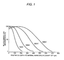
- a depth-dose curve is generally used.
- the treatment depth of an electron beam is also related to the specific gravity of a material to be irradiated, in addition to the accelerating voltage value.
- the depth-dose curve shows the relationship among the accelerating voltage value, the treatment depth and the relative dose showing treatment efficiency. For example, the relationship to a material having a specific gravity of 1 is shown in Fig. 1 .
- the relative dose is a value close to 100 in the depth range of 0 to 300 ⁇ m at an accelerating voltage value of 300 kV, which shows that uniform electron beam treatment is performed to the whole film.
- the pre-irradiation method electron beam treatment is performed to the substrate film at a high accelerating voltage in the atmosphere, and then, electron beam treatment is performed on both surfaces of the substrate film at a low accelerating voltage.
- the substrate film is inserted into a glass container, and thereafter, this container is subjected to vacuum deaeration, followed by replacement to an inert gas atmosphere. Then, a monomer from which oxygen gas has been removed by bubbling of an inert gas containing no oxygen or freeze deaeration, a mixed solution thereof or a monomer solution obtained by dissolving or diluting the monomer with a solvent is filled in the container containing the substrate film irradiated with the electron beam.
- the graft polymerization for introducing the graft chains into the substrate polymer is conducted usually at 30 to 150°C, and preferably at 40 to 80°C.
- the degree of grafting of the polymer largely depends on the molecular weight of the monomer to be polymerized. However, roughly, it is preferably from 6 to 150% by weight, and more preferably from 10 to 100% by weight, based on the substrate polymer before the polymerization. This degree of grafting can be changed by the irradiation dose, the polymerization temperature, the polymerization time and the like.
- a known method for introducing ion-exchange groups such as sulfonic acid groups into the graft polymer is disclosed, for example, in JP-A-2001-348439 .
- a graft-treated film is immersed in a chlorosufonic acid solution having a concentration of 0.2 to 0.5 mol/L using 1,2-dichloroethane as a solvent at room temperature to 80°C for 2 to 48 hours to conduct reaction. After the reaction for a predetermined period of time, the membrane is thoroughly washed.
- a sulfonating agent concentrated sulfuric acid, sulfur trioxide, sodium thiosulfate or the like may be used. It is not particularly limited as long as it can introduce the sulfonic acid groups. Further, ion-exchange groups such as carboxyl groups may be introduced together with the sulfonic acid groups.
- a graft monomer having an ion-exchange group When a graft monomer having an ion-exchange group is used, since the ion-exchange group has been introduced into the substrate polymer at the time when the graft polymerization reaction is terminated, it is unnecessary to separately introduce the ion-exchange group. Further, when a graft monomer having a derivative of an ion-exchange group is used, it is necessary to convert the derivative to the ion-exchange group by performing appropriate treatment after the graft polymerization reaction. For example, in the case of an ester group, it is converted to a carboxyl group by conducting hydrolysis.
- the sulfonic acid group which is a strong acid group is introduced, because more excellent conductivity is obtained.
- the determination of the ion-exchange group cannot be made. In these cases, distribution of the ion-exchange groups can be confirmed by substituting the ion-exchange groups by metal ions not contained in the electrolyte membrane, and confirming distribution of metal elements thereof.
- the content of the sulfonic acid group in each of outer regions is larger than the content of the sulfonic acid group in each of inner regions.
- the electrolyte membrane of the invention when A1 and A2 each represent the maximum value of the distribution amount of the sulfonic acid group in each of the outer regions, and B1 and B2 each represent the average value of maximum value and minimum value of the distribution amount of the sulfonic acid group in each of the inner regions, the above-mentioned A1, A2, B1 and B2 satisfy the following equation: 1.5 ⁇ (A1+A2)/(B1+B2) ⁇ 8.
- the S distribution ratio is preferably from 2 to 5.
- the ion-exchange capacity is 0.5 to 2 meq/g, and preferably 0.7 to 1.5 meq/g.
- the rate of change in area due to immersion in pure water at 25°C is preferably 40% or less, and more preferably 30% or less.
- the rate of change in area exceeds 40%, changes in area of the membrane, which are associated with water inclusion, become too large, resulting in failure to maintain well adhesion with the electrode.
- the electric conductivity at 25°C is preferably 0.03 ⁇ -1 cm -1 or more, and more preferably 0.05 ⁇ -1 cm -1 or more.
- the electric conductivity is less than 0.03 ⁇ -1 cm -1 , the electric resistance of the membrane increases, resulting in difficultly to obtain sufficient output.
- the electrolyte membrane of the invention has practically sufficient proton conductivity, chemical and thermal stability and mechanical characteristics, and is suitably used as a fuel cell membrane which can be used in solid polymer fuel cells or direct alcohol fuel cells using an alcohol such as methanol. Pure hydrogen, reformed hydrogen gas made from methanol, natural gas, or gasoline, alcohols such as methanol, dimethyl ether and the like can be used as fuels.
- the ion-exchange capacity (Iex) of an electrolyte membrane is represented by the following equation.
- Iex ion-exchange capacity
- the electric conductivity of the electrolyte membrane was measured by an alternating current method (Shin Jikken Kagaku Koza 19, Polymer Chemistry ⁇ II>, page 992, Maruzen).
- the measurement of the membrane resistance (Rm) was made by using an ordinary membrane resistance measurement cell and an LCR meter (E-4925A, manufactured by Hewlett-Packard).
- the cell was filled with a 1 M sulfuric acid aqueous solution at 25°C, and the resistance between platinum electrodes (distance: 5 mm) was measured by the presence or absence of the membrane.
- the electrolyte membrane (3 mm ⁇ 8 mm) prepared was embedded in an epoxy resin, followed by curing.
- the resulting cured body (5 mm ⁇ 10 mm) was cut with a microtome to expose a cross section. That was fixed to a sample holder and subjected to Pt-Pd vapor deposition to prepare a sample.
- FE-SEM S-4800 field emission scanning electron microscope
- XMA EMAX Energy EX-200 manufactured by Horiba, Ltd.
- the cross section of the sample was divided into four equal parts, A1 and A2 each were taken as the maximum value of the distribution amount of the sulfonic acid group in each of the outer regions, B1 and B2 each were taken as the average value of maximum value and minimum value of the distribution amount of the sulfonic acid group in each of the two inner regions, and the S distribution ratio [(A1+A2)/(B1+B2)] was calculated.
- Each of the electrolyte membranes prepared in Examples and Comparative Examples was put between two commercial electrodes (25 cm 2 , noble metal carrying amount: anode 4 mg/cm 2 , cathode 2 mg/cm 2 ), and hot pressed at a press pressure of 1.5 MPa at 180°C ⁇ 5 min to prepare a sample including the electrode-the electrolyte membrane-the electrode.
- output characteristic evaluation of DMFC was made under conditions of an operating temperature of 70°C; a methanol aqueous solution concentration of 2 mol/L and 0.8 ml/min; and stoichiometrically triple the amount of dry air, to measure the maximum output value P (mW/cm 2 ).
- a PVdF film (thickness: 50 ⁇ m, specific gravity: 1.8, a nonporous film) formed by a melt extrusion method was irradiated with an electron beam under a nitrogen atmosphere under conditions of an accelerating voltage value of 250 kV and an irradiation dose of 5 kGy.
- the film was placed in a glass separable container (inner diameter: 3 cm, height: 20 cm) equipped with a cock, and the container was filled with argon gas of 1 atm, after deaeration.
- a styrene-toluene mixed solution (a mixed solution of 50% by volume of styrene and 50% by volume of toluene) from which dissolved oxygen was previously removed by argon bubbling was introduced into this container under an argon atmosphere.
- the film was in a state where it was completely immersed in the mixed solution.
- heating was performed at 60°C for 5 hours to conduct graft polymerization.
- the film was thoroughly washed with toluene, and dried to obtain a graft membrane.
- This graft-polymerized PVdF film was immersed in a 0.3 M chlorosulfonic acid solution diluted with 1,2-dichloroethane, and heated at 60°C for 8 hours in a sealed state. Then, the film was washed with water and dried to obtain a sulfonated graft membrane, namely, an electrolyte membrane.
- a PVdF film (thickness: 50 ⁇ m, specific gravity: 1.8, a nonporous film) formed by a melt extrusion method was irradiated with an electron beam under a nitrogen atmosphere under conditions of an accelerating voltage value of 250 kV and an irradiation dose of 5 kGy. Subsequently, electron beam irradiation was performed on both surfaces of the PVdF film by using an ultra small-scale electron beam irradiation device (Min-EBSTEM-Chamber II, manufactured by Ushio Inc.) under a vacuum atmosphere under conditions of an accelerating voltage value of 25 kV and an irradiation dose of 20 kGy.
- an ultra small-scale electron beam irradiation device Min-EBSTEM-Chamber II, manufactured by Ushio Inc.
- the film was placed in a glass separable container (inner diameter: 3 cm, height: 20 cm) equipped with a cock, and the container was filled with argon gas of 1 atm. after deaeration. Subsequently, about 100 g of a styrene-toluene mixed solution (a mixed solution of 50% by volume of styrene and 50% by volume of toluene) from which dissolved oxygen was previously removed by argon bubbling was introduced into this container under an argon atmosphere. Here, the film was in a state where it was completely immersed in the mixed solution. After the introduction of the mixed solution, heating was performed at 60°C for 5 hours to conduct graft polymerization. After the reaction, the film was thoroughly washed with toluene, and dried to obtain a graft membrane.
- a styrene-toluene mixed solution a mixed solution of 50% by volume of styrene and 50% by volume of toluene
- This graft-polymerized PVdF film was immersed in a 0.3 M chlorosulfonic acid solution diluted with 1,2-dichloroethane, and heated at 60°C for 8 hours in a sealed state. Then, the film was washed with water and dried to obtain a sulfonated graft membrane, namely, an electrolyte membrane.
- An electrolyte membrane was obtained in the same manner as in Example I with the exception that the conditions of the second electron beam irradiation were changed to "an accelerating voltage value of 25 kV and an irradiation dose of 5 kGy".
- An electrolyte membrane was obtained in the same manner as in Example 1 with the exception that the conditions of the second electron beam irradiation were changed to "an accelerating voltage value of 25 kV and an irradiation dose of 80 kGy".
- An electrolyte membrane was obtained in the same manner as in Example 1 with the exception that the conditions of the first graft polymerization were changed to "60°C for 60 minutes" and that the conditions of the second electron beam irradiation were changed to "an accelerating voltage value of 25 kV and an irradiation dose of 5 kGy".
- An electrolyte membrane was obtained in the same manner as in Example 1 with the exception that the conditions of the first electron beam irradiation were changed to "an accelerating voltage value of 250 kV and an irradiation dose of 15 kGy" and that the conditions of the second electron beam irradiation were changed to "an accelerating voltage value of 25 kV and an irradiation dose of 80 kGy
- An electrolyte membrane was obtained in the same manner as in Example 1 with the exception that the conditions of the first electron beam irradiation were changed to "an accelerating voltage value of 250 kV and an irradiation dose of 7 kGy" and that the second electron beam irradiation and graft polymerization were not conducted.
- An electrolyte membrane was obtained in the same manner as in Example 1 with the exception that the conditions of the second electron beam irradiation were changed to "an accelerating voltage value of 25 kV and an irradiation dose of 2.5 kGy".
- An electrolyte membrane was obtained in the same manner as in Example 1 with the exception that the conditions of the second electron beam irradiation were changed to "an accelerating voltage value of 25 kV and an irradiation dose of 120 kGy".
- An electrolyte membrane was obtained in the same manner as in Example 1 with the exception that the conditions of the first graft polymerization were changed to "60°C for 30 minutes" and that the conditions of the second electron beam irradiation were changed to "an accelerating voltage value of 25 kV and an irradiation dose of 5 kGy".
- An electrolyte membrane was obtained in the same manner as in Example 1 with the exception that the conditions of the first electron beam irradiation were changed to "an accelerating voltage value of 250 kV and an irradiation dose of 20 kGy" and that the conditions of the second electron beam irradiation were changed to "an accelerating voltage value of 25 kV and an irradiation dose of 80 kGy".
- the electrolyte membrane of the invention has the structure in which the outer regions have a higher sulfonic acid group density than the inner regions.
- the sulfonic acid group density in the vicinity of a membrane surface is high, the interface resistance between the membrane and the electrode can be decreased. Further, since the sulfonic acid group density in the inside of the membrane is low, changes in area of the membrane, which are associated with water inclusion, can be inhibited, and adhesion with the electrode can be maintained well.
Landscapes
- Chemical & Material Sciences (AREA)
- General Chemical & Material Sciences (AREA)
- Life Sciences & Earth Sciences (AREA)
- Sustainable Development (AREA)
- Sustainable Energy (AREA)
- Engineering & Computer Science (AREA)
- Chemical Kinetics & Catalysis (AREA)
- Manufacturing & Machinery (AREA)
- Electrochemistry (AREA)
- Crystallography & Structural Chemistry (AREA)
- Spectroscopy & Molecular Physics (AREA)
- Physics & Mathematics (AREA)
- Fuel Cell (AREA)
- Conductive Materials (AREA)
- Manufacture Of Macromolecular Shaped Articles (AREA)
- Treatments Of Macromolecular Shaped Articles (AREA)
Applications Claiming Priority (2)
| Application Number | Priority Date | Filing Date | Title |
|---|---|---|---|
| JP2006355480A JP4986219B2 (ja) | 2006-12-28 | 2006-12-28 | 電解質膜 |
| PCT/JP2007/075188 WO2008081896A1 (ja) | 2006-12-28 | 2007-12-27 | 電解質膜 |
Publications (2)
| Publication Number | Publication Date |
|---|---|
| EP2109172A1 true EP2109172A1 (de) | 2009-10-14 |
| EP2109172A4 EP2109172A4 (de) | 2011-09-21 |
Family
ID=39588578
Family Applications (1)
| Application Number | Title | Priority Date | Filing Date |
|---|---|---|---|
| EP07860409A Withdrawn EP2109172A4 (de) | 2006-12-28 | 2007-12-27 | Elektrolytmembran |
Country Status (6)
| Country | Link |
|---|---|
| US (1) | US8133635B2 (de) |
| EP (1) | EP2109172A4 (de) |
| JP (1) | JP4986219B2 (de) |
| KR (1) | KR101298796B1 (de) |
| CN (1) | CN101578729B (de) |
| WO (1) | WO2008081896A1 (de) |
Families Citing this family (9)
| Publication number | Priority date | Publication date | Assignee | Title |
|---|---|---|---|---|
| JP5305283B2 (ja) * | 2008-02-29 | 2013-10-02 | 独立行政法人日本原子力研究開発機構 | 燃料電池用高分子電解質膜の製造方法、その電解質膜及びその膜を使用した燃料電池用膜電極接合体 |
| US11236196B2 (en) | 2014-11-18 | 2022-02-01 | Rensselaer Polytechnic Institute | Polymers and methods for their manufacture |
| CA2968110C (en) | 2014-11-18 | 2023-10-10 | Rensselaer Polytechnic Institute | Novel polymers and methods for their manufacture |
| US10199667B2 (en) * | 2016-11-30 | 2019-02-05 | Nissan North America, Inc. | Segmented cation-anion exchange membrane for self-humidification of fuel cells and method of making |
| US20200238272A1 (en) | 2017-07-06 | 2020-07-30 | Rensselaer Polytechnic Institute | Ionic functionalization of aromatic polymers for ion exchange membranes |
| CN112512668A (zh) | 2018-04-24 | 2021-03-16 | 伦斯勒理工学院 | 用于阴离子交换膜的芳香族聚合物的交联 |
| AU2019388889B2 (en) * | 2018-11-26 | 2025-05-01 | Rensselaer Polytechnic Institute | Phosphate anion-quaternary ammonium ion pair coordinated polymer membranes |
| CN111477923A (zh) * | 2020-03-24 | 2020-07-31 | 武汉惠强新能源材料科技有限公司 | 一种三层共挤复合质子交换膜及其制备方法 |
| CN111490278A (zh) * | 2020-03-24 | 2020-08-04 | 武汉惠强新能源材料科技有限公司 | 一种三层共挤质子交换膜及其制备方法 |
Family Cites Families (9)
| Publication number | Priority date | Publication date | Assignee | Title |
|---|---|---|---|---|
| JP3317452B2 (ja) | 1992-10-05 | 2002-08-26 | 株式会社レイテック | 改質ポリテトラフルオロエチレンとその製造方法 |
| JPH09102322A (ja) | 1995-07-31 | 1997-04-15 | Imura Zairyo Kaihatsu Kenkyusho:Kk | 燃料電池用の固体高分子電解質膜およびその製造方法 |
| JP3485032B2 (ja) * | 1999-07-02 | 2004-01-13 | トヨタ自動車株式会社 | 燃料電池および固体高分子電解質膜 |
| JP4568848B2 (ja) | 2000-06-07 | 2010-10-27 | 独立行政法人 日本原子力研究開発機構 | 広範囲なイオン交換容量のフッ素樹脂イオン交換膜及びその製造方法 |
| JP4871591B2 (ja) * | 2003-05-13 | 2012-02-08 | 旭硝子株式会社 | 固体高分子型燃料電池用電解質ポリマー、その製造方法及び膜・電極接合体 |
| JP4959924B2 (ja) * | 2004-03-16 | 2012-06-27 | 株式会社カネカ | プロトン伝導性高分子膜およびその製造方法並びにそれを使用した固体高分子形燃料電池 |
| JP2005353581A (ja) * | 2004-05-10 | 2005-12-22 | Toray Ind Inc | 電解質膜および膜電極複合体ならびに高分子電解質型燃料電池 |
| KR100657740B1 (ko) * | 2004-12-22 | 2006-12-14 | 주식회사 엘지화학 | 브랜치된 술폰화 멀티 블록 공중합체 및 이를 이용한전해질막 |
| JP5109311B2 (ja) | 2005-12-27 | 2012-12-26 | 日産自動車株式会社 | 膜電極接合体、および、これを用いた燃料電池 |
-
2006
- 2006-12-28 JP JP2006355480A patent/JP4986219B2/ja not_active Expired - Fee Related
-
2007
- 2007-12-27 KR KR1020097013224A patent/KR101298796B1/ko not_active Expired - Fee Related
- 2007-12-27 WO PCT/JP2007/075188 patent/WO2008081896A1/ja not_active Ceased
- 2007-12-27 EP EP07860409A patent/EP2109172A4/de not_active Withdrawn
- 2007-12-27 CN CN200780048710XA patent/CN101578729B/zh not_active Expired - Fee Related
- 2007-12-27 US US12/521,361 patent/US8133635B2/en not_active Expired - Fee Related
Also Published As
| Publication number | Publication date |
|---|---|
| EP2109172A4 (de) | 2011-09-21 |
| JP2008166159A (ja) | 2008-07-17 |
| KR101298796B1 (ko) | 2013-08-22 |
| CN101578729B (zh) | 2012-01-11 |
| US8133635B2 (en) | 2012-03-13 |
| CN101578729A (zh) | 2009-11-11 |
| KR20090102765A (ko) | 2009-09-30 |
| WO2008081896A1 (ja) | 2008-07-10 |
| US20100316933A1 (en) | 2010-12-16 |
| JP4986219B2 (ja) | 2012-07-25 |
Similar Documents
| Publication | Publication Date | Title |
|---|---|---|
| US8133635B2 (en) | Electrolyte membrane | |
| JP4568848B2 (ja) | 広範囲なイオン交換容量のフッ素樹脂イオン交換膜及びその製造方法 | |
| EP2110875A1 (de) | Polymer-elektrolytmembran, verfahren zu ihrer herstellung, membran-elektrodenbaugruppe und festpolymer-brennstoffzelle | |
| JP5004178B2 (ja) | 機械的強度に優れる高プロトン伝導性高分子電解質膜及びその製造方法 | |
| EP1110992B1 (de) | Fester Polymerelektrolyt mit hoher Dauerhaftigkeit | |
| EP1893323B1 (de) | Verfahren zur herstellung einer strahlungsbrennstoffzellenmembran mit verbesserter chemischer stabilität und membranelektrodenanordnung | |
| EP1806371A1 (de) | Elektrolytmaterial, elektrolytmembran und membran-elektroden-anordnung für eine feste polymerbrennstoffzelle | |
| JP5557430B2 (ja) | プロトン伝導性高分子電解質膜およびその製造方法ならびにそれを用いた膜−電極接合体および高分子電解質型燃料電池 | |
| WO2008023801A1 (en) | Polymer electrolyte membrane composed of aromatic polymer membrane base and method for producing the same | |
| EP1518289B1 (de) | Brennstoffzelle mit durch strahlung gepfropfter polymer-elektrolyt-membran | |
| JP4822389B2 (ja) | 耐酸化性の優れた電解質膜 | |
| EP2192645B1 (de) | Trennmembran für eine direkt-flüssigbrennstoffzelle und herstellungsverfahren dafür | |
| US7714027B2 (en) | Crosslinked aromatic polymer electrolyte membrane and method for producing same | |
| Sproll et al. | Membrane architecture with ion-conducting channels through swift heavy ion induced graft copolymerization | |
| JP4437663B2 (ja) | プロトン伝導性高分子電解質、プロトン伝導性高分子電解質膜及び膜−電極接合体、並びに固体高分子形燃料電池 | |
| JP4716363B2 (ja) | プロトン伝導性膜の製造方法 | |
| JP4499004B2 (ja) | スルホン化された高分子電解質膜の製造方法 | |
| JP4574514B2 (ja) | プロトン伝導性膜及びその製造方法 | |
| KR20080019284A (ko) | 고체 고분자 전해질막 및 그 제조 방법, 및 연료 전지 | |
| EP1863110B1 (de) | Elektrolytfilm mit ausgezeichneter adhäsion der elektrode | |
| JP2006307051A (ja) | 固体高分子電解質膜及びその製造方法、並びに燃料電池 | |
| TWI281283B (en) | Proton exchange membrane and manufacture thereof | |
| CN117397071A (zh) | 质子交换膜状物 | |
| JP2008181860A (ja) | 電解質膜の製造方法 | |
| JP2010153186A (ja) | プロトン伝導性高分子電解質膜とそれを用いた膜−電極接合体および高分子電解質型燃料電池 |
Legal Events
| Date | Code | Title | Description |
|---|---|---|---|
| PUAI | Public reference made under article 153(3) epc to a published international application that has entered the european phase |
Free format text: ORIGINAL CODE: 0009012 |
|
| 17P | Request for examination filed |
Effective date: 20090626 |
|
| AK | Designated contracting states |
Kind code of ref document: A1 Designated state(s): AT BE BG CH CY CZ DE DK EE ES FI FR GB GR HU IE IS IT LI LT LU LV MC MT NL PL PT RO SE SI SK TR |
|
| DAX | Request for extension of the european patent (deleted) | ||
| A4 | Supplementary search report drawn up and despatched |
Effective date: 20110824 |
|
| RIC1 | Information provided on ipc code assigned before grant |
Ipc: H01M 8/10 20060101ALI20110818BHEP Ipc: H01B 1/06 20060101ALI20110818BHEP Ipc: H01M 8/02 20060101AFI20110818BHEP |
|
| 17Q | First examination report despatched |
Effective date: 20120712 |
|
| STAA | Information on the status of an ep patent application or granted ep patent |
Free format text: STATUS: THE APPLICATION IS DEEMED TO BE WITHDRAWN |
|
| 18D | Application deemed to be withdrawn |
Effective date: 20121123 |