EP2109176B1 - Brennstoffzelle - Google Patents
Brennstoffzelle Download PDFInfo
- Publication number
- EP2109176B1 EP2109176B1 EP08790831.5A EP08790831A EP2109176B1 EP 2109176 B1 EP2109176 B1 EP 2109176B1 EP 08790831 A EP08790831 A EP 08790831A EP 2109176 B1 EP2109176 B1 EP 2109176B1
- Authority
- EP
- European Patent Office
- Prior art keywords
- small openings
- flow
- paths
- fuel cell
- flow space
- Prior art date
- Legal status (The legal status is an assumption and is not a legal conclusion. Google has not performed a legal analysis and makes no representation as to the accuracy of the status listed.)
- Not-in-force
Links
- 239000000446 fuel Substances 0.000 title claims description 80
- 239000012530 fluid Substances 0.000 claims description 84
- 239000012528 membrane Substances 0.000 claims description 6
- 239000003792 electrolyte Substances 0.000 claims description 3
- 239000001257 hydrogen Substances 0.000 description 57
- 229910052739 hydrogen Inorganic materials 0.000 description 57
- UFHFLCQGNIYNRP-UHFFFAOYSA-N Hydrogen Chemical compound [H][H] UFHFLCQGNIYNRP-UHFFFAOYSA-N 0.000 description 55
- 230000004941 influx Effects 0.000 description 37
- 238000004891 communication Methods 0.000 description 19
- 239000007789 gas Substances 0.000 description 9
- 239000003054 catalyst Substances 0.000 description 4
- 239000006185 dispersion Substances 0.000 description 4
- OKKJLVBELUTLKV-UHFFFAOYSA-N Methanol Chemical compound OC OKKJLVBELUTLKV-UHFFFAOYSA-N 0.000 description 3
- MWUXSHHQAYIFBG-UHFFFAOYSA-N nitrogen oxide Inorganic materials O=[N] MWUXSHHQAYIFBG-UHFFFAOYSA-N 0.000 description 3
- 239000005518 polymer electrolyte Substances 0.000 description 2
- 239000007787 solid Substances 0.000 description 2
- 239000000956 alloy Substances 0.000 description 1
- 229910045601 alloy Inorganic materials 0.000 description 1
- 238000003491 array Methods 0.000 description 1
- 238000007796 conventional method Methods 0.000 description 1
- 230000005611 electricity Effects 0.000 description 1
- 150000002431 hydrogen Chemical class 0.000 description 1
- 125000004435 hydrogen atom Chemical group [H]* 0.000 description 1
- 238000000034 method Methods 0.000 description 1
- 238000010248 power generation Methods 0.000 description 1
- 230000002265 prevention Effects 0.000 description 1
- 238000000926 separation method Methods 0.000 description 1
- XTQHKBHJIVJGKJ-UHFFFAOYSA-N sulfur monoxide Chemical class S=O XTQHKBHJIVJGKJ-UHFFFAOYSA-N 0.000 description 1
- 229910052815 sulfur oxide Inorganic materials 0.000 description 1
Images


Classifications
-
- H—ELECTRICITY
- H01—ELECTRIC ELEMENTS
- H01M—PROCESSES OR MEANS, e.g. BATTERIES, FOR THE DIRECT CONVERSION OF CHEMICAL ENERGY INTO ELECTRICAL ENERGY
- H01M8/00—Fuel cells; Manufacture thereof
- H01M8/24—Grouping of fuel cells, e.g. stacking of fuel cells
- H01M8/2465—Details of groupings of fuel cells
- H01M8/2484—Details of groupings of fuel cells characterised by external manifolds
-
- H—ELECTRICITY
- H01—ELECTRIC ELEMENTS
- H01M—PROCESSES OR MEANS, e.g. BATTERIES, FOR THE DIRECT CONVERSION OF CHEMICAL ENERGY INTO ELECTRICAL ENERGY
- H01M8/00—Fuel cells; Manufacture thereof
- H01M8/10—Fuel cells with solid electrolytes
- H01M2008/1095—Fuel cells with polymeric electrolytes
-
- Y—GENERAL TAGGING OF NEW TECHNOLOGICAL DEVELOPMENTS; GENERAL TAGGING OF CROSS-SECTIONAL TECHNOLOGIES SPANNING OVER SEVERAL SECTIONS OF THE IPC; TECHNICAL SUBJECTS COVERED BY FORMER USPC CROSS-REFERENCE ART COLLECTIONS [XRACs] AND DIGESTS
- Y02—TECHNOLOGIES OR APPLICATIONS FOR MITIGATION OR ADAPTATION AGAINST CLIMATE CHANGE
- Y02E—REDUCTION OF GREENHOUSE GAS [GHG] EMISSIONS, RELATED TO ENERGY GENERATION, TRANSMISSION OR DISTRIBUTION
- Y02E60/00—Enabling technologies; Technologies with a potential or indirect contribution to GHG emissions mitigation
- Y02E60/30—Hydrogen technology
- Y02E60/50—Fuel cells
Definitions
- the present invention relates to a fuel cell feeding an anode fluid from the manifold to each cell unit of the cell stack.
- Fuel cell is a generator with an energy density several fold those of the existing batteries. Fuel cell has characteristic features of higher energy efficiency and no or less nitrogen oxides or sulfur oxides in discharged gases. Therefore, fuel cell is an extremely effective device satisfying the demand as a next-generation electric source device.
- the cell of a fuel cell comprises an anode-side catalyst (anode) and a cathode-side catalyst (cathode) on both the sides of the solid polymer electrolyte membrane as an electrolyte membrane.
- anode anode
- cathode cathode-side catalyst
- a fuel cell of such stack structure is equipped with a manifold for uniformly dividing a fuel to each of the cell units to uniformly feed the fuel in the cell stack, so as to feed the fuel from the manifold to each of the cell units.
- the manifold is constructed with a second space for dispersion, which is arranged adjacent to the cell stack, and a first space where a hydrogen rich gas is fed.
- the hydrogen rich gas fed in the first space is transferred through a through hole to the second space, where the hydrogen rich gas is dispersed and fed to each of the cell units.
- Patent reference 1 JP-A-Hei 9-161828
- a fuel cell includes a cell unit, an inlet fuel-supply manifold, an outlet fuel-exhaust manifold, an inlet air-supply manifold and an outlet air-exhaust manifold.
- Each fuel inlet manifold comprises an outer plate and three thermal shields.
- the thermal shield nearest the outer plate has a single inlet opening, through which fuel from an inlet pipe flows. This fuel from this single opening is then divided and flows through holes provided in each of the remaining two thermal shields until it reaches an inner plate having holes aligned with individual flow paths forming part of the cell unit.
- the holes in the second and third thermal shields are narrow close to the fuel inlet pipe and wide far from it.
- the flow paths are supplied with fuel via respective conduits, which correspond with openings in a second plate. The fuel flows through a pipe and is divided into three paths before entering the space between the outer plate and the second plate.
- the hydrogen rich gas is necessarily dispersed in the second space according to the conventional technique, it was required to make the ratio of the volume of the second space to the whole volume of the first space and the second space larger. Unless the distance from the through hole to the cell units is at a certain dimension, therefore, the feed volume of the hydrogen rich gas varies depending on the positional relation between the through hole and each of the cell units, so that the manifold should inevitably be made as a larger type so as to uniformly feed the hydrogen rich gas to each of the cell units.
- a fuel cell has the features set forth in claim 1.
- the anode fluid fed from the side face of the flow space along the face direction through the flow conduit of the fluid supply plate is fed into the flow space to reduce the flow rate of the anode fluid and the anode fluid at a reduced flow rate is allowed to influx the paths in the block group to be dispersed in the small openings. Therefore, the anode fluid can be dispersed in a plurality of the small openings in such a limited space of the manifold of a thin type, so that the anode fluid can uniformly be fed to each of the cell units, even when the manifold is made as a thin type.
- a fuel cell is characterized in that the paths formed with the block group are plurally formed and the width of such paths remote from the opening part of the flow conduit into the flow space is larger than the width of such paths close to the opening part of the flow conduit into the flow space.
- the width of the paths remote from the opening part to which the anode fluid is fed is larger, so that the flow resistance in such remote paths is reduced for ready flowing.
- the anode fluid can be fed uniformly from a plurality of the paths into the small openings, despite the distances thereof from the opening part.
- a fuel cell is characterized in that the paths formed with the block group are plurally formed and the length of such paths remote from the opening part of the flow conduit into the flow space is shorter than the length of such paths close to the opening part of the flow conduit into the flow space.
- the loss of the flow pressure in the remote paths is reduced for ready flowing because the length of the paths remote from the opening part of the flow conduit into the flow space where the anode fluid is fed is shorter, so that the anode fluid can uniformly be fed from a plurality of the paths into the small openings, despite the distances thereof from the opening part.
- a fuel cell is characterized in that a separator plate is arranged in such a manner that the separator plate separates the flow space through the block group on the opposite side of the small openings into a plurality of spaces along the direction of the small openings arranged and additionally divides the anode fluid into a plurality of the spaces.
- the anode fluid can be dispersed at a uniform state into a plurality of the small openings since the separator plate divides the anode fluid in a plurality of the spaces.
- a fuel cell is characterized in that a separator wall for separating the flow space through the block group on the opposite side of the small openings is arranged along the direction of the small openings arranged, where the opening part of the flow conduit into the flow space is formed in a manner corresponding to a plurality of the spaces separated with the separator wall.
- the anode fluid can be transferred from the opening parts corresponding to a plurality of the spaces into a plurality of the spaces, so that the anode fluid can be dispersed in a plurality of the small openings in a secure and uniform manner.
- a fuel cell is characterized in that a block group and a fluid supply plate are additionally arranged on the bottom plate through the small openings on the opposite side of the block group and the fluid supply plate, along the face direction thereof.
- the anode fluid flowing in the paths between the block groups on both the sides of the small openings can be fed, so that the flow pressure of the anode fluid into the small openings can be raised to feed the anode fluid into the small openings.
- the opening parts of the flow conduits facing each other into the flow space are arranged in an inversed direction to each other along the direction of the small openings arranged.
- the anode fluid can be fed from the opening parts arranged in an inversed direction to each other along the direction of the small openings arranged, so that the feed distribution of the anode fluid along the direction of the small openings arranged can be suppressed.
- a fuel cell is characterized in that the small openings are arranged in such a manner that the small openings close to the opening parts of the flow conduits into the flow space are more apart from the block group lying between the opening parts and the small openings than the small openings remote from the opening parts.
- the micro openings are arranged at a slanting state between the block groups, so the feed distribution of the anode fluid can further be suppressed.
- a fuel cell is characterized in that a plurality of small openings facing the anode fluid path are arranged on the top plate and the cell stacks are individually arranged on the bottom part of the bottom plate and the top part of the top plate.
- the cell stacks are arranged on both the sides of the manifold, while the manifold lies between the cell stacks. Therefore, the anode fluid can be fed from the manifold of a thin type to many cells.
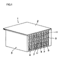
- Fig. 1 is a view of the appearance of a fuel cell in the first embodiment
- Fig. 2 is a perspective view of the decomposed outer manifold
- Fig. 3 shows the appearance of the inner face of the bottom plate
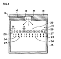
- Fig. 4 shows the status of a fuel flowing on the bottom plate.
- a fuel cell 1 in this mode is equipped with an outer manifold 2 as a manifold for feeding a fuel (hydrogen) as an anode fluid, where hydrogen is fed from the outer manifold 2 to a cell stack 3.
- the outer manifold 2 is connected with a fuel supply part not shown in the figures, for feeding hydrogen obtained from for example a hydrogen-absorbing alloy, while a control circuit not shown in the figures is connected with the electricity generation part of the cell stack 3.
- the cell 4 of the cell stack 3 is a membrane electrode assembly, where an anode-side catalyst (anode) and a cathode-side catalyst (cathode) are equipped on both the sides of a solid polymer electrolyte membrane as an electrolyte membrane. Then, a cell unit 11 is formed by alternately stacking a separator 5 with an anode fluid path (not shown in the figures) and a cathode fluid path 7 formed at a state of their sitting back to each other and the cell 4.
- the cell stack 3 is constructed by stacking together a plurality of the cell unit 11. So as to uniformly feed hydrogen in the cell stack 3 by uniformly dividing hydrogen in the anode fluid path of the separator 5 stacked in each cell unit 11 in the fuel cell 1 of such stack structure, an outer manifold 2 is equipped.
- the separator 5 is not limited to the shape where the anode fluid path and the cathode fluid path 7 are formed at a state of their sitting back to back.
- the separator may be in any shape where the anode fluid can be fed to the anode and the cathode fluid can be fed to the cathode.
- the outer manifold 2 comprises a top plate 12 and a bottom plate 13, where a hydrogen flow space 14 is formed between the inner face of the top plate 12 and the upper face of the bottom plate 13.
- a fluid supply plate 15 is arranged on the side part of the bottom plate 13 along the face direction at a state such that the fluid supply plate and the bottom plate are on the same face, while a flow conduit 16 for feeding hydrogen into the flow space 14 from the side part of the flow space 14 along the face direction is formed on the fluid supply plate 15.
- the top plate 12 is arranged over the bottom plate 13 and the fluid supply plate 15, while the flow conduit 16 is arranged between the inner face of the top plate 12 and the upper face of the fluid supply plate 15.
- An opening part 17 with an opening on the side of the flow space 14 is arranged in the flow conduit 16, and the opening part 17 is in communication with the influx part 18 on the bottom plate 13.
- the end of the flow conduit 16 is a fuel supply port 19.
- the fuel supply port 19 is connected with a fuel supply part not shown in the figure.
- a plurality of small openings 24 (12 small openings in the depicted example) facing the anode fluid path of the cell unit 11 (see Fig. 1 ) are arranged on the upper face of the bottom plate 13.
- the small openings 24 are arranged in an array in such a manner that one or more such small openings 24 can be arranged in one cell unit 11 (see Fig. 1 ).
- the small openings 24 are formed in an array of 12 small openings.
- a great number of small openings 24 may be formed for example by forming two or more such arrays, each array comprising 12 small openings.
- a block group 25 is formed between the influx part 18 and the small openings 24 on the upper face of the bottom plate 13, so that the block group 25 forms paths 26 for dispersing hydrogen fed from the influx part 18 into the small openings 24.
- a plurality of blocks 27 is arranged in the block group 25, while the spaces between the blocks 27 are the paths 26.
- the blocks are arranged in such a manner that the width of blocks 27 close to the influx part 18 (the opening part 17 of the flow conduit 16) is larger than the width of blocks 27 remote from the influx part 18 (the opening part 17 of the flow conduit 16).
- the width H of the paths 26 remote from the influx part 18 (the opening part 17 of the flow conduit 16) is larger than the width h of the paths 26 close to the influx part 18 (the opening part 17 of the flow conduit 16), so that the pressure loss in the paths 26 remote from the influx part 18 (the opening part 17 of the flow conduit 16) is reduced.
- a prevention wall preventing the efflux of hydrogen into the opposite side of the influx part 18 of hydrogen may be arranged through the small openings 24, on the opposite side of the block group 25, to securely retain the pressure for hydrogen supply into the small openings 24.
- hydrogen is fed from the fuel supply port 19 of the fluid supply plate 15 in the outer manifold 2, which is then transferred from the flow conduit 16 through the opening part 17 and the influx part 18 to the flow space 14, for dispersion along the plane direction. Hydrogen at a reduced flow rate due to the dispersion in the flow space 14 is divided in a plurality of the paths 26 in the block group 25 for flowing.
- the width H of the paths 26 remote from the opening part 17 of the flow conduit 16 is larger than the width h of the paths 26 close to the opening part 17 of the flow conduit 16, so that hydrogen transferred is uniformly divided in the paths 26 despite the distances from the opening part 17 of the flow conduit 16. Hydrogen uniformly divided in the paths 26 flows downward (along the direction crossing with the flow direction in the paths 26) to be fed to the anode fluid path of the cell unit 11 (see Fig. 1 ).
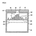
- Fig.5 shows the appearance of the inner face of the bottom plate of the outer manifold in a fuel cell in the second embodiment.
- the members except for the bottom plate 13 are the same as those in the first embodiment.
- the same members as the members for the bottom plate 13 shown in Fig. 3 (the first embodiment) are marked with the same symbols. Accordingly, overlapping descriptions are skipped.
- a block group 32 is formed between the influx part 18 and the small openings 24 on the upper face of the bottom plate 13.
- the block group 32 forms paths 33 for dispersing hydrogen fed from the communication hole 23 into the small openings 24.
- a plurality of blocks 34 are arranged in the block group 32, and the spaces between the blocks 34 are the path 33.
- the width (along the left and right direction in the figure) of the blocks 34 close to the influx part 18 (the opening part 17 of the flow conduit 16) is larger than the width of the blocks 34 remote from the influx part 18 (the opening part 17 of the flow conduit 16).
- the width H of the paths 33 remote from the influx part 18 (the opening part 17 of the flow conduit 16) is larger than the width h of the paths 33 close to the influx part 18 (the opening part 17 of the flow conduit 16), so that the pressure loss in the paths 33 remote from the influx part 18 (the opening part 17 of the flow conduit 16) is reduced.
- the length (along the upper and down direction in the figure) of the blocks 34 close to the influx part 18 is larger than the length of the blocks 34 remote from the influx part 18 (the opening part 17 of the flow conduit 16).
- the length I of the paths 33 remote from the influx part 18 is shorter than the length L of the paths 33 close to the influx part 18 (the opening part 17 of the flow conduit 16), so that the pressure loss in the paths 33 remote from the influx part 18 (the opening part 17 of the flow conduit 16) is reduced.
- Fig. 6 shows the appearance of the inner face of the bottom plate of the outer manifold in a fuel cell in the third embodiment.
- the members except for the bottom plate 13 are the same as those in the first embodiment, and the same members as the members for the bottom plate 13 (the first embodiment) shown in Fig. 3 are marked with the same symbols. Accordingly, overlapping descriptions are skipped.
- a separator plate 36 separating the flow space 14 lying through the block group 25 on the opposite side of the small openings 24 into two spaces 14a, 14b along the direction of the arranged small openings 24 (along the left and right direction in the figure) is arranged, while the separator plate 36 is arranged at a state such that the separator plate 36 may separate the influx part 18 (the opening part 17 of the flow conduit 16) into two equal portions.
- the separator plate 36 can divide hydrogen fed from the opening part 17 of the flow conduit 16 into the two spaces 14a, 14b. Therefore, hydrogen can be divided into the two spaces 14a, 14b with the separator plate 36, so that hydrogen can be dispersed at a uniform state into a plurality of the small openings 24.
- the separator plate 36 may be arranged on the bottom plate 13 in the second embodiment as shown in Fig. 5 .
- Fig. 7 shows the appearance of the inner face of the bottom plate of the outer manifold in the fuel cell in the fourth embodiment.
- the members except for the bottom plate 13 are the same members as in the first embodiment.
- the same members as the members for the bottom plate 13 shown in Fig. 3 (the first embodiment) are marked with the same symbols. Accordingly, overlapping descriptions are skipped.
- a separator wall 51 separating the flow space 14 through the block group 25 on the opposite side of the small openings 24 into two spaces 14a, 14b along the direction of the small openings 24 is arranged, so that influx parts 55a, 55b are formed in a manner corresponding to the two spaces 14a, 14b on the bottom plate 13.
- a fluid supply plate 52 is arranged at a state such that the fluid supply plate and the bottom plate 13 are on the same face, so that flow conduits 53a, 53b are formed on the fluid supply plate 52, for feeding hydrogen from the side of the flow space 14 along the face direction into the flow space 14.
- An opening part 54a in communication with the influx part 55a of the flow space 14a is arranged in the flow conduit 53a, while in the flow conduit 53b, an opening part 54b in communication with the influx part 55b of the flow space 14b is arranged.
- the ends of the flow conduits 53a, 53b are fuel supply ports 56a, 56b, and a fuel supply part not shown in the figure is connected with the fuel supply ports 56a, 56b.
- a top plate not shown in the figure is arranged over the bottom plate 13 and the fluid supply plate 52, and the flow conduits 53a, 53b are arranged between the inner face of the top plate and the upper face of the fluid supply plate 52.
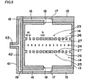
- Fig. 8 shows the appearance of the inner face of the bottom plate of the outer manifold in a fuel cell in the fifth embodiment.
- the members except for the bottom plate 13 are the same as those in the first embodiment, and the same members as the members for the bottom plate 13 shown in Fig. 3 (the first embodiment) are marked with the same symbols. Accordingly, overlapping descriptions are skipped.
- a block group 25 is additionally arranged through the small openings 24 on the opposite side (on the opposite side along the face direction) of the block group 25 on the bottom plate in the embodiment as shown in Fig. 3 .
- a block group 25 is additionally arranged on the lower side of the small openings 24 in the figure and faces the block group 25 on the upper side in the figure.
- a fluid supply plate 15 is arranged for feeding hydrogen from the paths 26 in the block groups 25 on both the sides of the small openings 24.
- a conduit communication plate 61 is arranged on the side of the bottom plate 13, and a communication path 62 is formed for allowing the fuel supply ports 19 of the two fluid supply plates 15 to be in communication. Then, a fuel supply path 63 is in communication with the communication path 62.
- hydrogen is fed from the fuel supply path 63, hydrogen is transferred through the communication path 62 to the fuel supply ports 19 of the two fluid supply plates 15, where hydrogen is dispersed from both the sides of the small openings 24 into the flow space 14. Hydrogen is fed from the paths 26 between the two block groups 25 into the individual small openings 24.
- the flow pressure of hydrogen into the small openings 24 between the two block groups 25 can be raised so that hydrogen can be fed stably into the small openings 24.
- Fig. 9 depicts the appearance of the inner face of the bottom plate of the outer manifold in a fuel cell in the sixth embodiment. Since the members except for the bottom plate 13 are the same as those in the first embodiment, the same members as those for the bottom plate 13 shown in Fig. 3 (the first embodiment) are marked with the same symbols. Accordingly, overlapping descriptions are skipped.
- the sixth embodiment differs from the fifth embodiment as shown in Fig. 8 , from the respects of the width of the paths in the block groups and the influx position of hydrogen on the fluid supply plate and additionally from the respect of the state of the arranged small openings. Therefore, the same members as the members in Fig. 8 are marked with the same symbols.
- fluid supply plates 71, 81 are individually arranged at a state such that the fluid supply plates and the bottom plate 13 are on the same face, while flow conduits 72, 82 are formed on the fluid supply plates 71, 81, for feeding hydrogen into the flow space 14 from both the sides of the flow space 14 (along the upper and down direction in the figure) along the face direction.
- An opening part 74 with an opening on the side of the flow space 14 is arranged in the flow conduit 72, while the opening part 74 is in communication with the influx part 75 on the bottom plate 13.
- the end of the flow conduit 72 is a fuel supply port 73.
- an opening part 84 with an opening on the side of the flow space 14 is arranged in the flow conduit 81, while the opening part 84 is in communication with the influx part 85 on the bottom plate 13.
- the end of the flow conduit 81 is the fuel supply port 83.
- a conduit communication plate 61 On the side part of the bottom plate 13 is arranged a conduit communication plate 61, and a communication path 62 allowing the fuel supply ports 73, 83 of two fluid supply plates 71, 81 to be in communication is formed on the conduit communication plate 61.
- a fuel supply path 63 is in communication with the communication path 62. When hydrogen is fed from the fuel supply path 63, specifically, hydrogen is transferred through the communication path 62 to the fuel supply ports 73, 83 of the two fluid supply plates 71, 81.
- a plurality of small openings 24 (12 small openings in the depicted example) facing the anode fluid path of the cell unit 11 (see Fig. 1 ) are formed. So as to arrange one or plural small openings 24 in one cell unit 11 (see Fig. 1 ), for example, the small openings 24 are arranged in an array.
- Paths 40 for dispersing hydrogen fed from the influx parts 75, 85 into the small openings 24 are formed with the block groups 38.
- a plurality of blocks 39 are arranged in the block groups 38, and the paths 40 are formed between the blocks 39.
- the width of the blocks 39 is structurally uniform, so that the width of the paths 40 is uniform.
- the opening parts 74, 84 of the flow conduits 72, 82 through the fluid supply plates 71, 81 facing each other into the flow space 14 are arranged in an inversed direction to each other along the direction of the small openings 24 arranged (along the left and right direction in the figure).
- the opening part 74 of the flow conduit 72 is arranged in the vicinity of the end on the left side in the figure, while the opening part 84 of the flow conduit 82 is arranged in the vicinity of the end on the right side in the figure.
- the small openings 24 are arranged in such a manner that the micro openings 24 close to the opening parts 74, 84 of the flow conduits 72, 82 are more apart from the block groups 38 lying between the opening parts 74, 84 than the small openings 24 remote from the opening parts 74, 84.
- the small openings 24 are arranged at a slanting state toward the upper right in the figure.
- hydrogen is fed from the opening parts 74, 84 arranged in an inversed direction to each other along the direction of the small openings 24 arranged, so that hydrogen is fed into the small openings 24 arranged at a state slanting toward the direction apart from the opening parts 74, 84, so that the hydrogen feed distribution along the direction of the arranged small openings 24 is more highly suppressed, leading to more uniform feeding of hydrogen into the small openings 24.
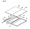
- Fig. 10 is a perspective view of the decomposed outer manifold of a fuel cell in the seventh embodiment; and Fig. 11 depicts the appearance of a fuel cell in the seventh embodiment.
- the same members as those in the first embodiment Figs. 1 and 2
- Figs. 1 and 2 are marked with the same symbols. Therefore, overlapping descriptions are skipped.
- an outer manifold 20 comprises small openings 22 formed through a top plate 28.
- the other structure is the same as that of the outer manifold shown in Fig. 2 .
- the small openings 22 are formed in a manner corresponding to the small openings 24 arranged through the bottom plate 13.
- individual cell stacks 3 are arranged on the lower side of the bottom plate 13 and the upper side of the top plate 28.
- the cell stacks 3 can be arranged through the outer manifold 20 on both the sides of the outer manifold 20.
- An anode fluid can be fed into two cells 4 with the outer manifold 20 of a thin type.
- hydrogen is exemplified as an anode fluid.
- the embodiment may be applicable to the supply of other fuels including methanol.
- an anode fluid can be dispersed into a plurality of small openings in the limited space of the manifold of a thin type, the anode fluid can be fed uniformly to each cell even when the manifold is made as such thin type.
Landscapes
- Life Sciences & Earth Sciences (AREA)
- Engineering & Computer Science (AREA)
- Manufacturing & Machinery (AREA)
- Sustainable Development (AREA)
- Sustainable Energy (AREA)
- Chemical & Material Sciences (AREA)
- Chemical Kinetics & Catalysis (AREA)
- Electrochemistry (AREA)
- General Chemical & Material Sciences (AREA)
- Fuel Cell (AREA)
Claims (9)
- Brennstoffzelle (1), umfassend eine Zelle mit einer Anode und einer Kathode, die durch eine Elektrolytenmembrane miteinander verbunden sind, einen Zellstapel (3), wobei mehrere von einer Zelleinheit (11) mit einem Separator (5), der mit einem Anodefluidpfad und der Zelle ausgestattet ist, zusammengestapelt sind, und einen Verteiler (2) zum Zuleiten eines Anodenfluids zu einer Position der Zelleinheit, welcher der Anodenfluidpfad zugewandt ist;
dadurch gekennzeichnet, dass:der Verteiler umfassteine Bodenplatte (13), die mit mehreren kleinen Öffnungen (24) ausgestattet ist, die dem Anodenfluidpfad zugewandt sind,eine Deckplatte (12), wo der Strömungsraum (14) des Anodenfluids an der Innenseite zwischen der oberen Fläche der Bodenplatte und der Deckplatte gebildet wird, undeine Fluidzuleitungsplatte (15), die mit einem Strömungskanal (16) zum Zuleiten eines Anodenfluids vom Seitenteil des Strömungsraumes entlang der Richtung der oberen Fläche der Bodenplatte in den Strömungsraum ausgestattet ist;eine Gruppe (25) von Blöcken (27), die Pfade (26) zum Dispergieren des Anodenfluids bildet, das aus dem Strömungskanal in die kleinen Öffnungen geleitet wird,an der oberen Fläche der Bodenplatte zwischen dem Öffnungsteil (17) des Strömungskanals der Fluidzuleitungsplatte in den Strömungsraum und den kleinen Öffnungen gebildet ist, wobei die der Pfade (26) zum Dispergieren des Anodenfluids zwischen den Blöcken gebildet sind; unddie Strömungsrate des Anodenfluids, das aus dem Strömungskanal (16) der Fluidzuleitungsplatte (15) zugeführt wird, im Strömungsraum (14) reduziert wird,und das Anodenfluid bei reduzierter Strömungsrate in die Pfade in der Blockgruppe (25) strömen gelassen wird, so dass es in die kleinen Öffnungen (14) dispergiert wird. - Brennstoffzelle nach Anspruch 1, dadurch gekennzeichnet, dass die Pfade (26), die mit der Blockgruppe (25) gebildet werden, mehrfach gebildet sind und die Breite (H) solcher Pfade fern des Öffnungsteils (17) des Strömungskanals (16) in den Strömungsraum (14) größer ist als die Breite (h) solcher Pfade nahe dem Öffnungsteil des Strömungskanals in den Strömungsraum.
- Brennstoffzelle nach Anspruch 1, dadurch gekennzeichnet, dass die Pfade (33), die mit der Blockgruppe (25) gebildet sind, mehrfach gebildet sind und die Länge (1) solcher Pfade fern des Öffnungsteils (17) des Strömungskanals (16) in den Strömungsraum (14) kürzer ist als die Länge (L) solcher Pfade nahe dem Öffnungsteil des Strömungskanals in den Strömungsraum.
- Brennstoffzelle nach Anspruch 1, dadurch gekennzeichnet, dass eine Separatorplatte (36) derart angeordnet ist, dass die Separatorplatte den Strömungsraum (14) durch die Blockgruppe (25) an der gegenüberliegenden Seite der kleinen Öffnungen (24) in mehrere Räume (14a, 14b) entlang der Anordnungsrichtung der kleinen Öffnungen trennt und zusätzlich das Anodenfluid in mehrere der Räume teilt.
- Brennstoffzelle nach Anspruch 1, dadurch gekennzeichnet, dass eine Separatorwand (51) zum Trennen des Strömungsraums durch die Blockgruppe (25) an der gegenüberliegenden Seite der kleinen Öffnungen (24) entlang der Anordnungsrichtung der kleinen Öffnungen angeordnet ist, wobei das Öffnungsteil des Strömungskanals (56a, 56b) in den Strömungsraum (14) in einer Weise gebildet ist, die mehreren Räumen (14a, 14b) entspricht, die mit der Separatorwand getrennt sind.
- Brennstoffzelle nach Anspruch 1, dadurch gekennzeichnet, dass eine Blockgruppe (25) und eine Fluidzuleitungsplatte (15) zusätzlich auf der Bodenplatte (13) an der den kleinen Öffnungen (24) gegenüberliegenden Seite der Blockgruppe (25) und der Fluidzuleitungsplatte (15) entlang der Flächenrichtung angeordnet sind.
- Brennstoffzelle nach Anspruch 6, dadurch gekennzeichnet, dass die Öffnungsteile (17) der einander zugewandten Strömungskanäle (16) in den Strömungsraum (14) in umgekehrter Richtung zueinander entlang der Anordnungsrichtung der kleinen Öffnungen (24) angeordnet sind.
- Brennstoffzelle nach Anspruch 7, dadurch gekennzeichnet, dass die kleinen Öffnungen (24) so angeordnet sind, dass die kleinen Öffnungen (24) nahe den Öffnungsteilen (74, 84) der Strömungskanäle in den Strömungsraum (14) weiter von der Blockgruppe (38) entfernt sind, die zwischen den Öffnungsteilen (74, 84) und den kleinen Öffnungen (24) liegt, als die kleinen Öffnungen fern den Öffnungsteilen.
- Brennstoffzelle nach Anspruch 1, dadurch gekennzeichnet, dass mehrere kleine Öffnungen (22), die dem Anodenfluidpfad zugewandt sind, an der Deckplatte (28) angeordnet sind und dass die Zellstapelt (3) einzeln auf dem unteren Teil der Bodenplatte (13) und dem oberen Teil der Deckplatte (28) angeordnet sind.
Applications Claiming Priority (2)
| Application Number | Priority Date | Filing Date | Title |
|---|---|---|---|
| JP2007181265A JP5207440B2 (ja) | 2007-07-10 | 2007-07-10 | 燃料電池 |
| PCT/JP2008/062027 WO2009008316A1 (ja) | 2007-07-10 | 2008-07-03 | 燃料電池 |
Publications (3)
| Publication Number | Publication Date |
|---|---|
| EP2109176A1 EP2109176A1 (de) | 2009-10-14 |
| EP2109176A4 EP2109176A4 (de) | 2012-02-29 |
| EP2109176B1 true EP2109176B1 (de) | 2014-12-24 |
Family
ID=40228494
Family Applications (1)
| Application Number | Title | Priority Date | Filing Date |
|---|---|---|---|
| EP08790831.5A Not-in-force EP2109176B1 (de) | 2007-07-10 | 2008-07-03 | Brennstoffzelle |
Country Status (5)
| Country | Link |
|---|---|
| US (1) | US8389179B2 (de) |
| EP (1) | EP2109176B1 (de) |
| JP (1) | JP5207440B2 (de) |
| CN (1) | CN101689673B (de) |
| WO (1) | WO2009008316A1 (de) |
Families Citing this family (4)
| Publication number | Priority date | Publication date | Assignee | Title |
|---|---|---|---|---|
| KR101132014B1 (ko) * | 2009-09-18 | 2012-04-02 | 삼성에스디아이 주식회사 | 분배기 및 이를 구비한 고체산화물 연료전지 모듈 |
| JP5065367B2 (ja) * | 2009-12-15 | 2012-10-31 | トヨタ自動車株式会社 | 燃料電池モジュール |
| JP5793432B2 (ja) * | 2012-01-11 | 2015-10-14 | 東芝燃料電池システム株式会社 | 燃料電池及び分配マニホールド |
| US10211478B2 (en) | 2015-10-07 | 2019-02-19 | Bloom Energy Corporation | Fuel cell stack column including stress-relief components |
Family Cites Families (14)
| Publication number | Priority date | Publication date | Assignee | Title |
|---|---|---|---|---|
| JPS6217962A (ja) | 1985-03-08 | 1987-01-26 | Hitachi Ltd | 燃料電池 |
| JP2610255B2 (ja) * | 1987-01-22 | 1997-05-14 | 株式会社東芝 | 溶融炭酸塩燃料電池 |
| JPH01281682A (ja) * | 1988-05-09 | 1989-11-13 | Toshiba Corp | 燃料電池 |
| JPH0758619B2 (ja) * | 1990-09-13 | 1995-06-21 | 株式会社日立製作所 | 複合大容量型ガスヘッダー構造 |
| JPH07118330B2 (ja) * | 1991-03-19 | 1995-12-18 | 株式会社日立製作所 | 燃料電池用ガスヘッダーおよびそれを用いた燃料電池 |
| JP3252473B2 (ja) * | 1992-08-12 | 2002-02-04 | 石川島播磨重工業株式会社 | 燃料電池 |
| JP3691141B2 (ja) * | 1995-12-14 | 2005-08-31 | 三洋電機株式会社 | 燃料電池 |
| CN2484648Y (zh) * | 2001-06-01 | 2002-04-03 | 上海神力科技有限公司 | 一种燃料电池的导流极板 |
| CN100356618C (zh) * | 2003-06-04 | 2007-12-19 | 上海神力科技有限公司 | 一种燃料电池导流双极板及其制造方法 |
| JP4121969B2 (ja) | 2004-02-24 | 2008-07-23 | 三洋電機株式会社 | アナログデジタル変換器 |
| JP4289674B2 (ja) | 2004-11-29 | 2009-07-01 | 本田技研工業株式会社 | 燃料噴射制御装置 |
| DE602006016389D1 (de) | 2005-10-20 | 2010-10-07 | Samsung Sdi Co Ltd | Teilpassives Brennstoffzellensystem |
| JP4851160B2 (ja) * | 2005-10-27 | 2012-01-11 | 日本電信電話株式会社 | 燃料電池 |
| JP5268044B2 (ja) * | 2007-02-16 | 2013-08-21 | セイコーインスツル株式会社 | 燃料電池 |
-
2007
- 2007-07-10 JP JP2007181265A patent/JP5207440B2/ja not_active Expired - Fee Related
-
2008
- 2008-07-03 US US12/450,048 patent/US8389179B2/en not_active Expired - Fee Related
- 2008-07-03 CN CN2008800241621A patent/CN101689673B/zh not_active Expired - Fee Related
- 2008-07-03 EP EP08790831.5A patent/EP2109176B1/de not_active Not-in-force
- 2008-07-03 WO PCT/JP2008/062027 patent/WO2009008316A1/ja not_active Ceased
Also Published As
| Publication number | Publication date |
|---|---|
| US8389179B2 (en) | 2013-03-05 |
| CN101689673B (zh) | 2013-03-13 |
| EP2109176A1 (de) | 2009-10-14 |
| EP2109176A4 (de) | 2012-02-29 |
| US20100104911A1 (en) | 2010-04-29 |
| JP2009021051A (ja) | 2009-01-29 |
| JP5207440B2 (ja) | 2013-06-12 |
| WO2009008316A1 (ja) | 2009-01-15 |
| CN101689673A (zh) | 2010-03-31 |
Similar Documents
| Publication | Publication Date | Title |
|---|---|---|
| EP2124283B1 (de) | Brennstoffzelle | |
| EP1147568B1 (de) | Mehrschicht-verteileranordnung mit effizientem volumenausbau für elektrochemische brennstoffzellenstapel | |
| RU2269842C2 (ru) | Блок топливных элементов на твердом полимерном электролите, батарея топливных элементов и способ подачи химически активного газа в топливный элемент | |
| KR101209684B1 (ko) | 분배 가이드를 갖는 스택 매니폴드 인서트 및 이를 포함하는 연료전지 스택 | |
| EP2860807B1 (de) | Brennstoffzellenstapel | |
| US9373853B2 (en) | Fuel cell employing multiple reactant supply passages | |
| US8617756B2 (en) | Fuel cell stack | |
| JP2006202524A (ja) | 燃料電池スタックのマニホールド構造 | |
| EP2109175A1 (de) | Brennstoffzelle | |
| EP2109176B1 (de) | Brennstoffzelle | |
| US20140349209A1 (en) | Fuel cell stack | |
| US8815464B2 (en) | Fuel cell | |
| JP7202107B2 (ja) | 電気化学セルスタック、燃料電池および水素製造装置 | |
| JP2006164762A (ja) | 燃料電池の配流特性の改善 | |
| US8455150B2 (en) | Fuel cell stack having reactant carrier plates delivering both anode and cathode reactants | |
| JP5123824B2 (ja) | 燃料電池スタックおよび燃料電池スタックの運転方法 | |
| EP1852929B1 (de) | Festoxidbrennstoffzelle | |
| JP7322265B2 (ja) | 電気化学セルスタック、燃料電池および水素製造装置 | |
| JP2007227398A (ja) | 燃料電池用セパレータ | |
| US20240204214A1 (en) | Separator for fuel cell | |
| US20230378486A1 (en) | Bipolar plate with media regulation and fuel cell stack | |
| JP5793432B2 (ja) | 燃料電池及び分配マニホールド | |
| JPH06333591A (ja) | 高電圧燃料電池システム | |
| CN116581351A (zh) | 包含喷嘴结构的用于燃料电池堆的反应物进料和回料总成 | |
| WO2025103585A1 (en) | Electrochemical cell unit |
Legal Events
| Date | Code | Title | Description |
|---|---|---|---|
| PUAI | Public reference made under article 153(3) epc to a published international application that has entered the european phase |
Free format text: ORIGINAL CODE: 0009012 |
|
| 17P | Request for examination filed |
Effective date: 20090721 |
|
| AK | Designated contracting states |
Kind code of ref document: A1 Designated state(s): AT BE BG CH CY CZ DE DK EE ES FI FR GB GR HR HU IE IS IT LI LT LU LV MC MT NL NO PL PT RO SE SI SK TR |
|
| DAX | Request for extension of the european patent (deleted) | ||
| A4 | Supplementary search report drawn up and despatched |
Effective date: 20120130 |
|
| RIC1 | Information provided on ipc code assigned before grant |
Ipc: H01M 8/10 20060101ALI20120124BHEP Ipc: H01M 8/24 20060101AFI20120124BHEP |
|
| 17Q | First examination report despatched |
Effective date: 20120903 |
|
| GRAP | Despatch of communication of intention to grant a patent |
Free format text: ORIGINAL CODE: EPIDOSNIGR1 |
|
| INTG | Intention to grant announced |
Effective date: 20140722 |
|
| GRAS | Grant fee paid |
Free format text: ORIGINAL CODE: EPIDOSNIGR3 |
|
| GRAA | (expected) grant |
Free format text: ORIGINAL CODE: 0009210 |
|
| AK | Designated contracting states |
Kind code of ref document: B1 Designated state(s): AT BE BG CH CY CZ DE DK EE ES FI FR GB GR HR HU IE IS IT LI LT LU LV MC MT NL NO PL PT RO SE SI SK TR |
|
| REG | Reference to a national code |
Ref country code: GB Ref legal event code: FG4D |
|
| REG | Reference to a national code |
Ref country code: CH Ref legal event code: EP |
|
| REG | Reference to a national code |
Ref country code: IE Ref legal event code: FG4D |
|
| REG | Reference to a national code |
Ref country code: AT Ref legal event code: REF Ref document number: 703549 Country of ref document: AT Kind code of ref document: T Effective date: 20150115 |
|
| REG | Reference to a national code |
Ref country code: DE Ref legal event code: R096 Ref document number: 602008036036 Country of ref document: DE Effective date: 20150219 |
|
| REG | Reference to a national code |
Ref country code: NL Ref legal event code: VDEP Effective date: 20141224 |
|
| PG25 | Lapsed in a contracting state [announced via postgrant information from national office to epo] |
Ref country code: FI Free format text: LAPSE BECAUSE OF FAILURE TO SUBMIT A TRANSLATION OF THE DESCRIPTION OR TO PAY THE FEE WITHIN THE PRESCRIBED TIME-LIMIT Effective date: 20141224 Ref country code: NO Free format text: LAPSE BECAUSE OF FAILURE TO SUBMIT A TRANSLATION OF THE DESCRIPTION OR TO PAY THE FEE WITHIN THE PRESCRIBED TIME-LIMIT Effective date: 20150324 Ref country code: LT Free format text: LAPSE BECAUSE OF FAILURE TO SUBMIT A TRANSLATION OF THE DESCRIPTION OR TO PAY THE FEE WITHIN THE PRESCRIBED TIME-LIMIT Effective date: 20141224 |
|
| REG | Reference to a national code |
Ref country code: LT Ref legal event code: MG4D |
|
| PG25 | Lapsed in a contracting state [announced via postgrant information from national office to epo] |
Ref country code: HR Free format text: LAPSE BECAUSE OF FAILURE TO SUBMIT A TRANSLATION OF THE DESCRIPTION OR TO PAY THE FEE WITHIN THE PRESCRIBED TIME-LIMIT Effective date: 20141224 Ref country code: SE Free format text: LAPSE BECAUSE OF FAILURE TO SUBMIT A TRANSLATION OF THE DESCRIPTION OR TO PAY THE FEE WITHIN THE PRESCRIBED TIME-LIMIT Effective date: 20141224 Ref country code: LV Free format text: LAPSE BECAUSE OF FAILURE TO SUBMIT A TRANSLATION OF THE DESCRIPTION OR TO PAY THE FEE WITHIN THE PRESCRIBED TIME-LIMIT Effective date: 20141224 Ref country code: GR Free format text: LAPSE BECAUSE OF FAILURE TO SUBMIT A TRANSLATION OF THE DESCRIPTION OR TO PAY THE FEE WITHIN THE PRESCRIBED TIME-LIMIT Effective date: 20150325 |
|
| REG | Reference to a national code |
Ref country code: AT Ref legal event code: MK05 Ref document number: 703549 Country of ref document: AT Kind code of ref document: T Effective date: 20141224 |
|
| PG25 | Lapsed in a contracting state [announced via postgrant information from national office to epo] |
Ref country code: NL Free format text: LAPSE BECAUSE OF FAILURE TO SUBMIT A TRANSLATION OF THE DESCRIPTION OR TO PAY THE FEE WITHIN THE PRESCRIBED TIME-LIMIT Effective date: 20141224 |
|
| PG25 | Lapsed in a contracting state [announced via postgrant information from national office to epo] |
Ref country code: ES Free format text: LAPSE BECAUSE OF FAILURE TO SUBMIT A TRANSLATION OF THE DESCRIPTION OR TO PAY THE FEE WITHIN THE PRESCRIBED TIME-LIMIT Effective date: 20141224 Ref country code: EE Free format text: LAPSE BECAUSE OF FAILURE TO SUBMIT A TRANSLATION OF THE DESCRIPTION OR TO PAY THE FEE WITHIN THE PRESCRIBED TIME-LIMIT Effective date: 20141224 Ref country code: RO Free format text: LAPSE BECAUSE OF FAILURE TO SUBMIT A TRANSLATION OF THE DESCRIPTION OR TO PAY THE FEE WITHIN THE PRESCRIBED TIME-LIMIT Effective date: 20141224 Ref country code: SK Free format text: LAPSE BECAUSE OF FAILURE TO SUBMIT A TRANSLATION OF THE DESCRIPTION OR TO PAY THE FEE WITHIN THE PRESCRIBED TIME-LIMIT Effective date: 20141224 Ref country code: CZ Free format text: LAPSE BECAUSE OF FAILURE TO SUBMIT A TRANSLATION OF THE DESCRIPTION OR TO PAY THE FEE WITHIN THE PRESCRIBED TIME-LIMIT Effective date: 20141224 |
|
| PG25 | Lapsed in a contracting state [announced via postgrant information from national office to epo] |
Ref country code: PL Free format text: LAPSE BECAUSE OF FAILURE TO SUBMIT A TRANSLATION OF THE DESCRIPTION OR TO PAY THE FEE WITHIN THE PRESCRIBED TIME-LIMIT Effective date: 20141224 Ref country code: AT Free format text: LAPSE BECAUSE OF FAILURE TO SUBMIT A TRANSLATION OF THE DESCRIPTION OR TO PAY THE FEE WITHIN THE PRESCRIBED TIME-LIMIT Effective date: 20141224 Ref country code: IS Free format text: LAPSE BECAUSE OF FAILURE TO SUBMIT A TRANSLATION OF THE DESCRIPTION OR TO PAY THE FEE WITHIN THE PRESCRIBED TIME-LIMIT Effective date: 20150424 |
|
| REG | Reference to a national code |
Ref country code: DE Ref legal event code: R097 Ref document number: 602008036036 Country of ref document: DE |
|
| PG25 | Lapsed in a contracting state [announced via postgrant information from national office to epo] |
Ref country code: DK Free format text: LAPSE BECAUSE OF FAILURE TO SUBMIT A TRANSLATION OF THE DESCRIPTION OR TO PAY THE FEE WITHIN THE PRESCRIBED TIME-LIMIT Effective date: 20141224 |
|
| PLBE | No opposition filed within time limit |
Free format text: ORIGINAL CODE: 0009261 |
|
| STAA | Information on the status of an ep patent application or granted ep patent |
Free format text: STATUS: NO OPPOSITION FILED WITHIN TIME LIMIT |
|
| 26N | No opposition filed |
Effective date: 20150925 |
|
| PG25 | Lapsed in a contracting state [announced via postgrant information from national office to epo] |
Ref country code: IT Free format text: LAPSE BECAUSE OF FAILURE TO SUBMIT A TRANSLATION OF THE DESCRIPTION OR TO PAY THE FEE WITHIN THE PRESCRIBED TIME-LIMIT Effective date: 20141224 |
|
| PG25 | Lapsed in a contracting state [announced via postgrant information from national office to epo] |
Ref country code: MC Free format text: LAPSE BECAUSE OF FAILURE TO SUBMIT A TRANSLATION OF THE DESCRIPTION OR TO PAY THE FEE WITHIN THE PRESCRIBED TIME-LIMIT Effective date: 20141224 Ref country code: SI Free format text: LAPSE BECAUSE OF FAILURE TO SUBMIT A TRANSLATION OF THE DESCRIPTION OR TO PAY THE FEE WITHIN THE PRESCRIBED TIME-LIMIT Effective date: 20141224 |
|
| REG | Reference to a national code |
Ref country code: CH Ref legal event code: PL |
|
| PG25 | Lapsed in a contracting state [announced via postgrant information from national office to epo] |
Ref country code: LU Free format text: LAPSE BECAUSE OF FAILURE TO SUBMIT A TRANSLATION OF THE DESCRIPTION OR TO PAY THE FEE WITHIN THE PRESCRIBED TIME-LIMIT Effective date: 20150703 |
|
| REG | Reference to a national code |
Ref country code: IE Ref legal event code: MM4A |
|
| PG25 | Lapsed in a contracting state [announced via postgrant information from national office to epo] |
Ref country code: CH Free format text: LAPSE BECAUSE OF NON-PAYMENT OF DUE FEES Effective date: 20150731 Ref country code: LI Free format text: LAPSE BECAUSE OF NON-PAYMENT OF DUE FEES Effective date: 20150731 |
|
| REG | Reference to a national code |
Ref country code: FR Ref legal event code: ST Effective date: 20160331 |
|
| PG25 | Lapsed in a contracting state [announced via postgrant information from national office to epo] |
Ref country code: BE Free format text: LAPSE BECAUSE OF FAILURE TO SUBMIT A TRANSLATION OF THE DESCRIPTION OR TO PAY THE FEE WITHIN THE PRESCRIBED TIME-LIMIT Effective date: 20141224 Ref country code: FR Free format text: LAPSE BECAUSE OF NON-PAYMENT OF DUE FEES Effective date: 20150731 |
|
| PG25 | Lapsed in a contracting state [announced via postgrant information from national office to epo] |
Ref country code: IE Free format text: LAPSE BECAUSE OF NON-PAYMENT OF DUE FEES Effective date: 20150703 |
|
| PG25 | Lapsed in a contracting state [announced via postgrant information from national office to epo] |
Ref country code: MT Free format text: LAPSE BECAUSE OF FAILURE TO SUBMIT A TRANSLATION OF THE DESCRIPTION OR TO PAY THE FEE WITHIN THE PRESCRIBED TIME-LIMIT Effective date: 20141224 |
|
| PG25 | Lapsed in a contracting state [announced via postgrant information from national office to epo] |
Ref country code: BG Free format text: LAPSE BECAUSE OF FAILURE TO SUBMIT A TRANSLATION OF THE DESCRIPTION OR TO PAY THE FEE WITHIN THE PRESCRIBED TIME-LIMIT Effective date: 20141224 Ref country code: HU Free format text: LAPSE BECAUSE OF FAILURE TO SUBMIT A TRANSLATION OF THE DESCRIPTION OR TO PAY THE FEE WITHIN THE PRESCRIBED TIME-LIMIT; INVALID AB INITIO Effective date: 20080703 |
|
| PG25 | Lapsed in a contracting state [announced via postgrant information from national office to epo] |
Ref country code: CY Free format text: LAPSE BECAUSE OF FAILURE TO SUBMIT A TRANSLATION OF THE DESCRIPTION OR TO PAY THE FEE WITHIN THE PRESCRIBED TIME-LIMIT Effective date: 20141224 |
|
| PG25 | Lapsed in a contracting state [announced via postgrant information from national office to epo] |
Ref country code: TR Free format text: LAPSE BECAUSE OF FAILURE TO SUBMIT A TRANSLATION OF THE DESCRIPTION OR TO PAY THE FEE WITHIN THE PRESCRIBED TIME-LIMIT Effective date: 20141224 |
|
| PG25 | Lapsed in a contracting state [announced via postgrant information from national office to epo] |
Ref country code: PT Free format text: LAPSE BECAUSE OF FAILURE TO SUBMIT A TRANSLATION OF THE DESCRIPTION OR TO PAY THE FEE WITHIN THE PRESCRIBED TIME-LIMIT Effective date: 20141224 |
|
| PGFP | Annual fee paid to national office [announced via postgrant information from national office to epo] |
Ref country code: DE Payment date: 20180619 Year of fee payment: 11 Ref country code: GB Payment date: 20180627 Year of fee payment: 11 |
|
| REG | Reference to a national code |
Ref country code: DE Ref legal event code: R119 Ref document number: 602008036036 Country of ref document: DE |
|
| GBPC | Gb: european patent ceased through non-payment of renewal fee |
Effective date: 20190703 |
|
| PG25 | Lapsed in a contracting state [announced via postgrant information from national office to epo] |
Ref country code: DE Free format text: LAPSE BECAUSE OF NON-PAYMENT OF DUE FEES Effective date: 20200201 Ref country code: GB Free format text: LAPSE BECAUSE OF NON-PAYMENT OF DUE FEES Effective date: 20190703 |