EP2109204A1 - Analyse eines Unterstationsautomationssystems - Google Patents
Analyse eines Unterstationsautomationssystems Download PDFInfo
- Publication number
- EP2109204A1 EP2109204A1 EP08154381A EP08154381A EP2109204A1 EP 2109204 A1 EP2109204 A1 EP 2109204A1 EP 08154381 A EP08154381 A EP 08154381A EP 08154381 A EP08154381 A EP 08154381A EP 2109204 A1 EP2109204 A1 EP 2109204A1
- Authority
- EP
- European Patent Office
- Prior art keywords
- value
- ied
- communication network
- values
- substation
- Prior art date
- Legal status (The legal status is an assumption and is not a legal conclusion. Google has not performed a legal analysis and makes no representation as to the accuracy of the status listed.)
- Withdrawn
Links
Images

Classifications
-
- H—ELECTRICITY
- H02—GENERATION; CONVERSION OR DISTRIBUTION OF ELECTRIC POWER
- H02J—ELECTRIC POWER NETWORKS; CIRCUIT ARRANGEMENTS OR SYSTEMS FOR SUPPLYING OR DISTRIBUTING ELECTRIC POWER; SYSTEMS FOR STORING ELECTRIC ENERGY
- H02J13/00—Circuit arrangements for providing remote monitoring or remote control of equipment in a power distribution network
- H02J13/10—Circuit arrangements for providing remote monitoring or remote control of equipment in a power distribution network characterised by displaying of information or by user interaction, e.g. supervisory control and data acquisition [SCADA] systems
-
- H—ELECTRICITY
- H02—GENERATION; CONVERSION OR DISTRIBUTION OF ELECTRIC POWER
- H02J—ELECTRIC POWER NETWORKS; CIRCUIT ARRANGEMENTS OR SYSTEMS FOR SUPPLYING OR DISTRIBUTING ELECTRIC POWER; SYSTEMS FOR STORING ELECTRIC ENERGY
- H02J13/00—Circuit arrangements for providing remote monitoring or remote control of equipment in a power distribution network
- H02J13/18—Circuit arrangements for providing remote monitoring or remote control of equipment in a power distribution network characterised by the remotely-controlled equipment, e.g. converters or transformers
- H02J13/333—Circuit arrangements for providing remote monitoring or remote control of equipment in a power distribution network characterised by the remotely-controlled equipment, e.g. converters or transformers the equipment forming part of substations
-
- Y—GENERAL TAGGING OF NEW TECHNOLOGICAL DEVELOPMENTS; GENERAL TAGGING OF CROSS-SECTIONAL TECHNOLOGIES SPANNING OVER SEVERAL SECTIONS OF THE IPC; TECHNICAL SUBJECTS COVERED BY FORMER USPC CROSS-REFERENCE ART COLLECTIONS [XRACs] AND DIGESTS
- Y02—TECHNOLOGIES OR APPLICATIONS FOR MITIGATION OR ADAPTATION AGAINST CLIMATE CHANGE
- Y02E—REDUCTION OF GREENHOUSE GAS [GHG] EMISSIONS, RELATED TO ENERGY GENERATION, TRANSMISSION OR DISTRIBUTION
- Y02E60/00—Enabling technologies; Technologies with a potential or indirect contribution to GHG emissions mitigation
-
- Y—GENERAL TAGGING OF NEW TECHNOLOGICAL DEVELOPMENTS; GENERAL TAGGING OF CROSS-SECTIONAL TECHNOLOGIES SPANNING OVER SEVERAL SECTIONS OF THE IPC; TECHNICAL SUBJECTS COVERED BY FORMER USPC CROSS-REFERENCE ART COLLECTIONS [XRACs] AND DIGESTS
- Y04—INFORMATION OR COMMUNICATION TECHNOLOGIES HAVING AN IMPACT ON OTHER TECHNOLOGY AREAS
- Y04S—SYSTEMS INTEGRATING TECHNOLOGIES RELATED TO POWER NETWORK OPERATION, COMMUNICATION OR INFORMATION TECHNOLOGIES FOR IMPROVING THE ELECTRICAL POWER GENERATION, TRANSMISSION, DISTRIBUTION, MANAGEMENT OR USAGE, i.e. SMART GRIDS
- Y04S10/00—Systems supporting electrical power generation, transmission or distribution
- Y04S10/16—Electric power substations
-
- Y—GENERAL TAGGING OF NEW TECHNOLOGICAL DEVELOPMENTS; GENERAL TAGGING OF CROSS-SECTIONAL TECHNOLOGIES SPANNING OVER SEVERAL SECTIONS OF THE IPC; TECHNICAL SUBJECTS COVERED BY FORMER USPC CROSS-REFERENCE ART COLLECTIONS [XRACs] AND DIGESTS
- Y04—INFORMATION OR COMMUNICATION TECHNOLOGIES HAVING AN IMPACT ON OTHER TECHNOLOGY AREAS
- Y04S—SYSTEMS INTEGRATING TECHNOLOGIES RELATED TO POWER NETWORK OPERATION, COMMUNICATION OR INFORMATION TECHNOLOGIES FOR IMPROVING THE ELECTRICAL POWER GENERATION, TRANSMISSION, DISTRIBUTION, MANAGEMENT OR USAGE, i.e. SMART GRIDS
- Y04S10/00—Systems supporting electrical power generation, transmission or distribution
- Y04S10/40—Display of information, e.g. of data or controls
Definitions
- the invention relates to the field of Substation Automation systems with a standardized configuration representation. It departs from a method of analysing a Substation Automation system as described in the preamble of claim 1.
- Substations for power distribution in high and medium voltage power networks include primary or field devices such as electrical cables, lines, bus bars, switches, breakers, power transformers and instrument transformers arranged in switch yards and/or bays. These primary devices are operated in an automated way via a Substation Automation (SA) system responsible for controlling, protecting and monitoring of substations.
- SA Substation Automation
- the SA system comprises programmable secondary devices, so-called Intelligent Electronic Devices (IED), interconnected in a SA communication network, and interacting with the primary devices via a process interface.
- IED Intelligent Electronic Devices
- the IEC standard 61850 "communication networks and systems in substations" decouples the substation-specific application functionality from the substation communication-specific issues and to this end, defines an abstract object model for compliant substations, and a method how to access these objects over a network via an Abstract Communication Service Interface (ACSI).
- ACSI Abstract Communication Service Interface
- OWS Operator Work Station
- An abstract data model incorporates SA functionality in terms of logical nodes grouped into logical devices and allocated to the IEDs as the physical devices.
- the communication-specific issues are handled via an ISO/OSI communication stack presently comprising a stack with MMS/TCP/IP/Ethernet and an optical, wireless or other media-type physical layer.
- the data model including attributes like time stamps or validity indications is realized by the application layer of the communication stack, messages for time-critical or safety-related communication, i.e. the Generic Object Oriented Substation Events (GOOSE) such as trips and blockings, as well as for analogue Sampled Values (SV), are mapped directly to the Ethernet link layer of the communication stack.
- GOOSE Generic Object Oriented Substation Events
- SV analogue Sampled Values
- the SCL language is used to describe the capabilities of a particular IED or IED type in an IED Capability Description (ICD). It enumerates the communication and application functionality of the physical device as delimited e.g. by the number of I/O ports.
- ICD IED Capability Description
- a Substation Configuration Description (SCD) file in SCL language describes a model of a particular substation, the IED functions in terms of logical nodes, and the communication connections.
- the SCD file comprises (1) a switch yard naming and topology description, (2) IED configuration description (functions in terms of logical nodes), (3) Relation between switch yard and IED functions, (4) communication network description.
- a particular IED is used within an SA system, then based on its ICD type description an object instance of the IED is inserted into the corresponding SCD file.
- the SCL language then allows specifying typical or individual values for data attributes carried by the instance and related to the particular IED, e.g. values for configuration attributes and setting parameters.
- the connection between the power process and the SA system is described in the SCL language by attaching logical nodes to elements of the primary equipment. Typically, a switch control logical node is attached to a switching device, whereas a measurement logical node or a protection function logical node is allocated to a bay unit.
- the SA configuration (topology, IED configuration and communication setup) is derived from the customer requirements and stored in an SCD file.
- SCD file For the actual installation or commissioning, all or parts of the configuration information previously engineered needs to be transferred to the physical devices, and the IEDs themselves need to be configured properly.
- inconsistencies between the SCD file and the actual configuration of an individual IED may arise. Such inconsistencies should be identified and remedied by a test and commissioning engineer during or after a commissioning of an SA system.
- the patent application EP-A 1 850 447 describes a Substation Automation testing tool which combines the information found in the SCL (Substation Configuration Language) File of a substation (Substation Configuration Description) or an IED (IED Capability description) with substation-relevant data extracted from the Substation Communication network traffic.
- SCL Substation Configuration Language
- IED IED Capability description
- a Substation Automation (SA) system for a substation of an electric power transmission or distribution system comprises Intelligent Electronic Devices (IED) interconnected by a SA communication network and repeatedly exchanging network messages.
- the SA system, or an individual component thereof is analysed or tested by capturing or intercepting network messages and extracting there from values of a particular process quantity of the substation, such as a switch position or a bus voltage, or of the SA system, such as a trip signal or a quality status indication.
- These successive values are displayed to a user in a chronological order as a function of a time-stamp associated to each value in a graphical manner, i.e. not entirely in alphanumerical form.
- a discontinuity indicator is likewise displayed in a suitable graphical form in case two successive values of the process quantity differ, thus marking, highlighting or emphasizing this fact to the user.
- the graphical representation of the time resolved process data and of the changes in the respective values simplifies a comparison among process quantities as well as an analysis of a temporal relation between their respective changes. It supports a user such as a testing or commissioning engineer in identifying and analysing problems more rapidly and thus contributes to a reduction of the time and effort for commissioning or testing an SA system.
- the intercepted network traffic may include process quantities of any type such as Boolean type used for trip signals, Integer type enumerating a few discrete integer values for switch positions, and Integer or Floating Point numbers used for RMS measurements.
- the discontinuity indicator may be a change in the graphical representation of the values, e.g. their dot size or colour, or it may comprise an additional marker such as an arrow pointing to the dot or icon representing the changed value.
- the discontinuity indicator may include a suitable interpolation between successive values, such as a line with a discontinuous or abrupt change in its representation, e.g. its line thickness or colour, and/or exhibiting a kink or step change at a particular point in time comprised in the interval defined by the two time-stamps associated to previous and the changed value of the process quantity, respectively. Depicting a discontinuity indicator may also be triggered by missing or substantially delayed cyclically transmitted telegrams.
- the SA system is compliant with the standard IEC 61850, meaning that standardized configuration descriptions of the SA system or of individual IEDs are available and that the network messages are standardized Ethernet frames with IEC 61850 conforming telegrams.
- the configuration information about the SA system and about the IEDs is contained respectively in a standardized Substation Configuration Description (SCD) or an IED Capability Description (ICD), or may be obtained from the IEDs via MMS Services.
- SCD Substation Configuration Description
- ICD IED Capability Description
- MMS Services MMS Services
- process quantities are enhanced with identifying information about the process quantity (type, ID, quality, etc.) by analysing IEC 61850 compliant frames such as MMS (Manufacturing Message Specification), GOOSE (Generic Object Oriented Substation Events) or SV (analogue Sampled Values).
- IEC 61850 compliant frames such as MMS (Manufacturing Message Specification), GOOSE (Generic Object Oriented Substation Events) or SV (analogue Sampled Values).
- the values of two or more distinct process quantities originating from one or several IEDs are displayed with respect to a common or shared time axis, facilitating comparison across the distinct process quantities and revealing the time relations of the their respective changes. For instance, signals from two different IEDs may be displayed. If a first IED cyclically transmits a binary trip status, the time delay between the first (off-cycle) message comprising a trip command and a response message from a second IED indicating that a circuit breaker has opened can be determined. Furthermore, the second process quantity may also be a process signal with a quasicontinuous range of (measurement) values, the graphical display thus resembling a kind of digital oscilloscope. Such a set-up depicting the above trip status together with corresponding Sampled Values represents a simple type of disturbance recording.
- a combination of the above preferred variant and advantageous embodiment enables a user to select the process quantities to be displayed concurrently independently of the originating IEDs or an internal structure of the telegrams comprising the process data.
- related process quantities can be identified according to their functional context, i.e. the enhanced semantic or contextual information about the substation as derived from the standardized configuration description of the latter.
- related process quantities can be grouped and designated accordingly.
- the process data from frames that were saved into a specific file or buffer in a previous session may be displayed.
- process data captured from the network is displayed instantaneously.
- the content of the display is updated spontaneously in on line mode, e.g. the time axis is adapted and interconnecting lines are redrawn in order to connect to the dot or icon representing the latest value added.
- the associated time-stamps may either relate to the time when the process data was received by an analyser, or may be taken from the header of the received frame.
- the present invention also relates to a computer program product including computer program code means for controlling one or more processors of an SA system analyser connected to an SA communication network and configured to store substation configuration data.
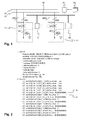
- Fig.1 shows a single line diagram of a part or section of an exemplary substation at an assumed voltage level of e.g. 110 kV, together with some communication links and Substation Automation (SA) or secondary equipment.
- the model of a switch yard at single line level contains the topological respectively electrical connections between primary equipment.
- the substation comprises a double bus bar configuration with two bus bars 10, 10', each of them feeding two bays 11, 11' via disconnectors QB1 to QB4.
- Each bay comprises a circuit breaker QA1, a disconnector QC1 and an earthing switch QE1.
- the corresponding excerpt of the SA system depicts, in bold lines, a communication network 20 connected to two IEDs 21, 22, which both host logical nodes of class CSWI (switch control).
- Substation specific SCL files 23 comprise a Substation Configuration Description (SCD) of the substation including IEDs 21, 22, or an IED Capability Description (ICD) of a first IED 21.
- SCD Substation Configuration Description
- ICD IED Capability Description
- a laptop computer as an analyser 24 is connected to the SA communication network 20 or inter-bay bus at strategic locations. Suitable or strategic locations include the vicinity of the Ethernet switch of the corresponding bay comprising the IED 21, or the vicinity of an Operator Work Station where most of the network traffic converges.
- One type of communication in modem SA systems is based on a publisher - subscriber model using multicast Ethernet frames.
- any client including analyser 24, connected to the network will, if configured accordingly, receive all GOOSE information.
- Tools have been developed that allow for analysis of the network traffic, i.e. basic Ethernet and related TCP/IP traffic, being exchanged in a SA network.
- the analysis of the extracted data comprises an interpretation with the help of the description found in the SCD or ICD file.
- Enhanced information thus generated relates e.g. to the specific data type or format of a piece of data extracted, i.e. whether a particular numerical value is represented in Integer, String or hexadecimal format.
- the information may also reveal the semantic meaning of the value and indicate e.g. a switch position or any other attribute that has to be known or set for a proper operation of the substation automation system.
- Fig.2 shows a possible representation of a single GOOSE frame, i.e. of its decoded content, in textual form.
- the frame is divided in header information and DataSet information.
- the IEC 61850 compliant configuration file usually a SCD file or any other SCL compatible file.
- the Data transferred in the frame are ordered according the dataset Information specified in the SCD file.
- the interpreted lines A and B both refer to a first instance "1" of a logical node of class "XCBR" (circuit breaker) in a logical device instance "C1" with prefix "QA1_1" on IED "AA1D1Q10A1".
- GOOSE communication between IEDs can be displayed by Network Analyzers that listen to GOOSE frames in a simple list based way.
- Network Analyzers that listen to GOOSE frames in a simple list based way.
- the same information might be transmitted several times over the Ethernet. Displaying the values in a textual way in this case makes it hard to identify the packet where the value of the data has changed.
- graphically representing the contents of exemplary GOOSE frames transmitted over the communication network appears more user-friendly.
- Fig.3 depicts, in the top half, an exemplary graphical representation of a first process quantity Y of an enumerating integer type "DPos", and corresponding to a switch position with the discrete integer values bad, open, closed and intermediate.
- the values depicted have been extracted from successively received IEC 61850 conforming telegrams.
- the first three values Y1, Y2, Y3 (corresponding to a sequence close-open-close) of the quantity Y are provided with references, and an exemplary discontinuity indicator Z in the form of a vertical line connecting the level "open” to the value Y3 at the level "closed” is surrounded by an oval.
- a second process quantity Y' of Boolean type is depicted.
- Discontinuity indicators in the form of vertical lines emphasize to the user the changes in the process quantity from "on” to "off” or vice versa.
- One exemplary discontinuity indicator has been surrounded by an oval and denoted by the reference Z'.
- the two process quantities Y, Y' originate from two distinct IEDs but are functionally related and thus share a common time axis in Fig.3 .
- Fig.4 finally is a screen-shot like representation of three distinct process quantities on a time scale spanning approximately 35 seconds.
- the topmost is of Integer type and represents a process quantity or measurand reported by a first IED, with values oscillating between 0 and 200 VA.
- the other two process quantities depicted are of the types DPos and Boolean as described in connection with Fig.3 , and originate from a second IED.
Landscapes
- Engineering & Computer Science (AREA)
- Power Engineering (AREA)
- Remote Monitoring And Control Of Power-Distribution Networks (AREA)
Priority Applications (2)
| Application Number | Priority Date | Filing Date | Title |
|---|---|---|---|
| EP08154381A EP2109204A1 (de) | 2008-04-11 | 2008-04-11 | Analyse eines Unterstationsautomationssystems |
| PCT/EP2009/054191 WO2009124958A1 (en) | 2008-04-11 | 2009-04-08 | Analysis of a substation automation system |
Applications Claiming Priority (1)
| Application Number | Priority Date | Filing Date | Title |
|---|---|---|---|
| EP08154381A EP2109204A1 (de) | 2008-04-11 | 2008-04-11 | Analyse eines Unterstationsautomationssystems |
Publications (1)
| Publication Number | Publication Date |
|---|---|
| EP2109204A1 true EP2109204A1 (de) | 2009-10-14 |
Family
ID=39731428
Family Applications (1)
| Application Number | Title | Priority Date | Filing Date |
|---|---|---|---|
| EP08154381A Withdrawn EP2109204A1 (de) | 2008-04-11 | 2008-04-11 | Analyse eines Unterstationsautomationssystems |
Country Status (2)
| Country | Link |
|---|---|
| EP (1) | EP2109204A1 (de) |
| WO (1) | WO2009124958A1 (de) |
Cited By (12)
| Publication number | Priority date | Publication date | Assignee | Title |
|---|---|---|---|---|
| EP2355412A1 (de) * | 2010-02-05 | 2011-08-10 | Omicron electronics GmbH | Verfahren und Vorrichtung zum Bewerten einer elektrischen Anlage eines elektrischen Energiesystems |
| EP2362577A1 (de) * | 2010-02-23 | 2011-08-31 | ABB Technology AG | Analyse der Kommunikationskonfiguration in einem Prozesssteuersystem |
| CN102564785A (zh) * | 2011-12-20 | 2012-07-11 | 施耐德万高(天津)电气设备有限公司 | 一种自动转换开关电器的自动检验装置 |
| EP2618228A1 (de) | 2012-01-17 | 2013-07-24 | ABB Technology AG | Analyse der Datenkommunikation in einer Prozesssteuerung oder in Untergeräte eines Automatisierungssystems |
| CN103329125A (zh) * | 2010-10-29 | 2013-09-25 | 电话有限公司 | 用于管理工业监督和控制系统中的通信的方法和系统 |
| EP2701340A1 (de) * | 2012-08-21 | 2014-02-26 | Omicron electronics GmbH | Verfahren zur Überwachung des Betriebs eines elektrischen Leistungssystems und Überwachungssystem |
| WO2014029652A1 (en) * | 2012-08-24 | 2014-02-27 | Abb Technology Ag | Communication configuration analysis in process control systems |
| CN103915897A (zh) * | 2014-02-28 | 2014-07-09 | 电信科学技术仪表研究所 | 一种数字化变电站采样值的监测方法及其监测装置 |
| US8804547B2 (en) * | 2008-08-18 | 2014-08-12 | Abb Technology Ag | Analyzing communication configuration in a process control system |
| CN105487002A (zh) * | 2015-11-26 | 2016-04-13 | 国家电网公司 | 变电站保护压板位置在线监测系统 |
| EP3367637A1 (de) * | 2017-02-23 | 2018-08-29 | Schneider Electric Industries SAS | Unterstationsspannungsreplika basierend auf digitaler spannung |
| WO2020245143A1 (en) | 2019-06-03 | 2020-12-10 | Abb Power Grids Switzerland Ag | Device and method for controlling an interface for a power utility |
Families Citing this family (2)
| Publication number | Priority date | Publication date | Assignee | Title |
|---|---|---|---|---|
| CN102761106B (zh) * | 2012-07-10 | 2014-10-22 | 清华大学 | 一种智能变电站集成保护的快速起动及相量计算方法 |
| CN103258041B (zh) * | 2013-05-23 | 2015-07-22 | 广东电网有限责任公司电力科学研究院 | 基于通用数据访问接口的tc57视图构建方法和系统 |
Citations (5)
| Publication number | Priority date | Publication date | Assignee | Title |
|---|---|---|---|---|
| US5768148A (en) * | 1996-04-03 | 1998-06-16 | General Electric Company | Man machine interface for power management control systems |
| US20020173927A1 (en) * | 2001-05-21 | 2002-11-21 | Benton Vandiver | System for testing of intelligent electronic devices with digital communications |
| US6904385B1 (en) * | 1998-05-29 | 2005-06-07 | Powerweb, Inc. | Multi-utility energy control system with internet energy platform having diverse energy-related engines |
| WO2006060371A2 (en) * | 2004-11-30 | 2006-06-08 | Abb Research Ltd. | Intelligent configuration system for power distribution feeder reclosers and switches |
| EP1850447A1 (de) | 2006-04-24 | 2007-10-31 | Abb Research Ltd. | Konfigurationsüberprüfung eines intelligenten elektronischen Geräts |
-
2008
- 2008-04-11 EP EP08154381A patent/EP2109204A1/de not_active Withdrawn
-
2009
- 2009-04-08 WO PCT/EP2009/054191 patent/WO2009124958A1/en not_active Ceased
Patent Citations (5)
| Publication number | Priority date | Publication date | Assignee | Title |
|---|---|---|---|---|
| US5768148A (en) * | 1996-04-03 | 1998-06-16 | General Electric Company | Man machine interface for power management control systems |
| US6904385B1 (en) * | 1998-05-29 | 2005-06-07 | Powerweb, Inc. | Multi-utility energy control system with internet energy platform having diverse energy-related engines |
| US20020173927A1 (en) * | 2001-05-21 | 2002-11-21 | Benton Vandiver | System for testing of intelligent electronic devices with digital communications |
| WO2006060371A2 (en) * | 2004-11-30 | 2006-06-08 | Abb Research Ltd. | Intelligent configuration system for power distribution feeder reclosers and switches |
| EP1850447A1 (de) | 2006-04-24 | 2007-10-31 | Abb Research Ltd. | Konfigurationsüberprüfung eines intelligenten elektronischen Geräts |
Cited By (21)
| Publication number | Priority date | Publication date | Assignee | Title |
|---|---|---|---|---|
| US8804547B2 (en) * | 2008-08-18 | 2014-08-12 | Abb Technology Ag | Analyzing communication configuration in a process control system |
| EP2355412A1 (de) * | 2010-02-05 | 2011-08-10 | Omicron electronics GmbH | Verfahren und Vorrichtung zum Bewerten einer elektrischen Anlage eines elektrischen Energiesystems |
| AU2011200436B2 (en) * | 2010-02-05 | 2013-09-12 | Omicron Electronics Gmbh | Method and device for evaluating an electrical installation of an electrical power system |
| EP2362577A1 (de) * | 2010-02-23 | 2011-08-31 | ABB Technology AG | Analyse der Kommunikationskonfiguration in einem Prozesssteuersystem |
| CN103329125A (zh) * | 2010-10-29 | 2013-09-25 | 电话有限公司 | 用于管理工业监督和控制系统中的通信的方法和系统 |
| CN102564785A (zh) * | 2011-12-20 | 2012-07-11 | 施耐德万高(天津)电气设备有限公司 | 一种自动转换开关电器的自动检验装置 |
| US9654345B2 (en) | 2012-01-17 | 2017-05-16 | Abb Schweiz Ag | Analyzing data communication in a process control or substation automation system |
| EP2618228A1 (de) | 2012-01-17 | 2013-07-24 | ABB Technology AG | Analyse der Datenkommunikation in einer Prozesssteuerung oder in Untergeräte eines Automatisierungssystems |
| WO2013107772A1 (en) | 2012-01-17 | 2013-07-25 | Abb Technology Ag | Analysing data communication in a process control or substation automation system |
| CN103633639A (zh) * | 2012-08-21 | 2014-03-12 | 欧米克朗电子仪器有限公司 | 监视电力系统运行的方法和监视系统 |
| EP2701340A1 (de) * | 2012-08-21 | 2014-02-26 | Omicron electronics GmbH | Verfahren zur Überwachung des Betriebs eines elektrischen Leistungssystems und Überwachungssystem |
| US10338111B2 (en) | 2012-08-21 | 2019-07-02 | Omicron Electronics Gmbh | Method of monitoring operation of an electric power system and monitoring system |
| CN103633639B (zh) * | 2012-08-21 | 2016-08-10 | 欧米克朗电子仪器有限公司 | 监视电力系统运行的方法和监视系统 |
| WO2014029652A1 (en) * | 2012-08-24 | 2014-02-27 | Abb Technology Ag | Communication configuration analysis in process control systems |
| US10338544B2 (en) | 2012-08-24 | 2019-07-02 | Abb Schweiz Ag | Communication configuration analysis in process control systems |
| CN103915897A (zh) * | 2014-02-28 | 2014-07-09 | 电信科学技术仪表研究所 | 一种数字化变电站采样值的监测方法及其监测装置 |
| CN103915897B (zh) * | 2014-02-28 | 2017-02-01 | 电信科学技术仪表研究所 | 一种数字化变电站采样值的监测方法及其监测装置 |
| CN105487002A (zh) * | 2015-11-26 | 2016-04-13 | 国家电网公司 | 变电站保护压板位置在线监测系统 |
| EP3367637A1 (de) * | 2017-02-23 | 2018-08-29 | Schneider Electric Industries SAS | Unterstationsspannungsreplika basierend auf digitaler spannung |
| US11100262B2 (en) | 2017-02-23 | 2021-08-24 | Schneider Electric Industries Sas | Substation voltage replica based on digital voltage |
| WO2020245143A1 (en) | 2019-06-03 | 2020-12-10 | Abb Power Grids Switzerland Ag | Device and method for controlling an interface for a power utility |
Also Published As
| Publication number | Publication date |
|---|---|
| WO2009124958A1 (en) | 2009-10-15 |
Similar Documents
| Publication | Publication Date | Title |
|---|---|---|
| WO2009124958A1 (en) | Analysis of a substation automation system | |
| US8165841B2 (en) | Intelligent electronic device configuration inspection | |
| US8789182B2 (en) | Security event logging in process control | |
| EP3050259B1 (de) | Testen eines automatisierungssystems eines umspannwerks | |
| CN102685036B (zh) | Iec 61850变电站网关 | |
| US20090070051A1 (en) | Intelligent electronic device configuration verification | |
| CN104040447B (zh) | 分析过程控制或者分站自动化系统中的数据通信 | |
| US10374415B2 (en) | Load restoration in a high or medium voltage substation | |
| EP2540036B1 (de) | Analyse der kommunikationskonfiguration in einem iec 61850 prozesssteuersystem | |
| Ali et al. | Methodology & tools for performance evaluation of IEC 61850 GOOSE based protection schemes | |
| US10338544B2 (en) | Communication configuration analysis in process control systems | |
| EP4254704A1 (de) | Verfahren zum überwachen des betriebs eines elektrischen leistungssystems und überwachungssystem | |
| Wester et al. | Practical applications of peer-to-peer messaging in industrial facilities | |
| Ushakov et al. | iec 61850 digital communication protocols | |
| Gholizadeh | Iec 61850 standard and its capabilities in protection systems | |
| Dolezilek | Using Information From Relays to Improve the Power System–Revisited | |
| Tibbals et al. | Case Study: New Testing and Verification Practices for Virtual Wiring Among IEDs Via Ethernet Communications | |
| CN118233298A (zh) | 一种新增合智装置的免配置方法 | |
| Tibbals et al. | Case study: confidence in Ethernet IEC 61850 virtual wiring via innovative new testing and verification practices |
Legal Events
| Date | Code | Title | Description |
|---|---|---|---|
| PUAI | Public reference made under article 153(3) epc to a published international application that has entered the european phase |
Free format text: ORIGINAL CODE: 0009012 |
|
| AK | Designated contracting states |
Kind code of ref document: A1 Designated state(s): AT BE BG CH CY CZ DE DK EE ES FI FR GB GR HR HU IE IS IT LI LT LU LV MC MT NL NO PL PT RO SE SI SK TR |
|
| AX | Request for extension of the european patent |
Extension state: AL BA MK RS |
|
| AKX | Designation fees paid | ||
| REG | Reference to a national code |
Ref country code: DE Ref legal event code: 8566 |
|
| STAA | Information on the status of an ep patent application or granted ep patent |
Free format text: STATUS: THE APPLICATION IS DEEMED TO BE WITHDRAWN |
|
| 18D | Application deemed to be withdrawn |
Effective date: 20100415 |