EP2109212A1 - Moteur sans balai à aimant permanent régulé en flux direct utilisant un contrôle sans capteur - Google Patents
Moteur sans balai à aimant permanent régulé en flux direct utilisant un contrôle sans capteur Download PDFInfo
- Publication number
- EP2109212A1 EP2109212A1 EP09251090A EP09251090A EP2109212A1 EP 2109212 A1 EP2109212 A1 EP 2109212A1 EP 09251090 A EP09251090 A EP 09251090A EP 09251090 A EP09251090 A EP 09251090A EP 2109212 A1 EP2109212 A1 EP 2109212A1
- Authority
- EP
- European Patent Office
- Prior art keywords
- motor
- permanent magnet
- set forth
- along
- stator
- Prior art date
- Legal status (The legal status is an assumption and is not a legal conclusion. Google has not performed a legal analysis and makes no representation as to the accuracy of the status listed.)
- Granted
Links
- 230000004907 flux Effects 0.000 title claims abstract description 23
- 230000001105 regulatory effect Effects 0.000 title claims abstract description 6
- 230000005291 magnetic effect Effects 0.000 claims description 20
- 238000004804 winding Methods 0.000 claims description 11
- 230000005294 ferromagnetic effect Effects 0.000 claims description 8
- 239000003302 ferromagnetic material Substances 0.000 claims description 5
- 230000002093 peripheral effect Effects 0.000 claims 2
- 238000000034 method Methods 0.000 description 4
- 230000035699 permeability Effects 0.000 description 4
- 239000004020 conductor Substances 0.000 description 3
- 238000001514 detection method Methods 0.000 description 3
- 230000033228 biological regulation Effects 0.000 description 2
- 230000001276 controlling effect Effects 0.000 description 2
- 238000013461 design Methods 0.000 description 2
- 229910045601 alloy Inorganic materials 0.000 description 1
- 239000000956 alloy Substances 0.000 description 1
- 238000013459 approach Methods 0.000 description 1
- 238000010276 construction Methods 0.000 description 1
- 230000007423 decrease Effects 0.000 description 1
- 239000011888 foil Substances 0.000 description 1
- 238000003475 lamination Methods 0.000 description 1
- 239000010410 layer Substances 0.000 description 1
- 239000006247 magnetic powder Substances 0.000 description 1
- 238000012986 modification Methods 0.000 description 1
- 230000004048 modification Effects 0.000 description 1
- 238000012544 monitoring process Methods 0.000 description 1
- 230000010349 pulsation Effects 0.000 description 1
- 229920006395 saturated elastomer Polymers 0.000 description 1
- 239000002356 single layer Substances 0.000 description 1
- 239000007787 solid Substances 0.000 description 1
- 238000012546 transfer Methods 0.000 description 1
Images


Classifications
-
- H—ELECTRICITY
- H02—GENERATION; CONVERSION OR DISTRIBUTION OF ELECTRIC POWER
- H02P—CONTROL OR REGULATION OF ELECTRIC MOTORS, ELECTRIC GENERATORS OR DYNAMO-ELECTRIC CONVERTERS; CONTROLLING TRANSFORMERS, REACTORS OR CHOKE COILS
- H02P6/00—Arrangements for controlling synchronous motors or other dynamo-electric motors using electronic commutation dependent on the rotor position; Electronic commutators therefor
- H02P6/14—Electronic commutators
- H02P6/16—Circuit arrangements for detecting position
- H02P6/18—Circuit arrangements for detecting position without separate position detecting elements
- H02P6/182—Circuit arrangements for detecting position without separate position detecting elements using back-emf in windings
-
- H—ELECTRICITY
- H02—GENERATION; CONVERSION OR DISTRIBUTION OF ELECTRIC POWER
- H02K—DYNAMO-ELECTRIC MACHINES
- H02K29/00—Motors or generators having non-mechanical commutating devices, e.g. discharge tubes or semiconductor devices
- H02K29/06—Motors or generators having non-mechanical commutating devices, e.g. discharge tubes or semiconductor devices with position sensing devices
- H02K29/12—Motors or generators having non-mechanical commutating devices, e.g. discharge tubes or semiconductor devices with position sensing devices using detecting coils using the machine windings as detecting coil
-
- H—ELECTRICITY
- H02—GENERATION; CONVERSION OR DISTRIBUTION OF ELECTRIC POWER
- H02K—DYNAMO-ELECTRIC MACHINES
- H02K3/00—Details of windings
- H02K3/46—Fastening of windings on the stator or rotor structure
- H02K3/48—Fastening of windings on the stator or rotor structure in slots
- H02K3/487—Slot-closing devices
- H02K3/493—Slot-closing devices magnetic
Definitions
- This application relates to a permanent magnet flux regulated motor, wherein no sensor is necessary to provide position feedback of the location of the rotor.
- stator may include slots which are closed by ferromagnetic wedges.
- the wedges are provided with control coils fed with current. By controlling the current through the control coils, the overall magnetic flux can be controlled.
- a sensor could be provided; however, a sensor would add to the cost and weight.
- Another method of sensorless control is to sense the inductance variation along the quadrature and direct axes, known as the d and q axes.
- the direct axis is the center axis of the poles of the permanent magnets, while the quadrature axis is shifted by 45°.
- This last method is most reliable, and can be implemented at very low speeds, including a zero speed.
- standard permanent magnet motor designs result in very small differences between the inductances along the d and q axes, and thus make implementation of sensorless control utilizing this method difficult.
- a rotor to be associated with a permanent magnet flux regulated motor is constructed such that it will have increased saliency.
- the amount of ferromagnetic material through which the d axis and the q axis extend is made to be different, such that the difference in their inductances will also be more readily apparent, and a control will be able to more easily identify the position of the rotor.
- a rotor not shown in Figure 1
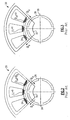
- the stator 20 is slotted.
- Stator slots are provided with wedges 22.
- control coils 24 are provided.
- the control coils may receive a DC or an AC current.
- the coils 24 may be connected in series to create a control winding.
- the slot wedges 22 behave as shunts for a magnetic flux produced by the permanent magnet motor. If the reluctance of the wedges is low, a portion of the magnetic flux is shunted by the wedges. While Figure 1 shows a double layer stator winding or wedges 22, the proposed systems also contemplate a single layer. Stator teeth 23 are positioned between the wedges 22.
- the wedges 22 may be made of a laminated ferromagnetic alloys or sintered magnetic powders.
- the magnetic wedges with the control coils can be inserted directly into conventional stator slots.
- the control coils 24 can also be wound with rectangular conductors or foil conductors.
- slot wedges can be stamped together with the stator teeth and after inserting the stator windings into the slots, a wound star-shaped stator core can be pressed into a ring-shaped stator ferromagnetic yoke. This is essentially the construction shown in Figure 4 , however it is not limiting on this application.
- the reluctance of a ferromagnetic material is inversely proportional to its magnetic permeability. If the control current in the control coils 24 is zero, the reluctance of the magnetic shunt into the wedges 22 is low because its magnetic permeability is high. Almost the total air gap magnetic flux produced by the permanent magnets will pass through the slot wedges. This is as shown in Figure 2 , which illustrates the flow when the current in the coils 24 is zero. The back EMF induced in the stator windings is small because the magnetic flux linked with the stator winding is very small. Relative to the permanent magnet flux, the electromagnetic torque is minimal.
- the magnetic flux linked with the stator windings increases, and so does the back EMF induced in the stator windings and the electromagnetic torque.
- the electromagnetic torque can be controlled as well as the EMF.
- the rotor magnetic flux can induce some AC voltage in the control winding. This voltage can be cancelled by connecting the same terminals (i.e., beginning with beginning and end with end of neighboring shunt coils). Such connection can typically only be done with DC control current.
- Proposed embodiments of a permanent magnet rotor 40 are shown in Figure 4 .
- the magnets 42 are positioned inward of ferromagnetic portions or caps 43.
- the d axis passes through the ferromagnetic portions and the permanent magnets, while the q axis does not.
- the inductances along those two axes will be starkly different, particularly when compared to existing non-salient permanent magnet rotors.
- Figure 5 shows another embodiment having ferromagnetic rotor core 50 wherein fingers 52 separate the permanent magnets 42 along the q axis. Still, the result will be a marked difference in the inductances along the two axes.
- variable inductance due to the difference between the direct and quadrature axes is sensed by monitoring line-to-neutral voltage of un-energized phase winding during 6-step commutation at a high carrier frequency.
- the measured voltage variation at carrier frequency is used to identify the position of the rotor as disclosed in the prior art, US Patent 5,363,032 .
- machines such as those shown in Figures 1-3 , can be provided with simple position feedback about their permanent magnet rotors.
- Standard stator laminations may be used.
- the machine has a topology which is typical of standard machines. Good heat transfer is provided because losses can be dissipated in the stator. Further, the mass and volume of the overall motor is smaller, and the machine is less expensive than machines requiring sensors.
Landscapes
- Engineering & Computer Science (AREA)
- Power Engineering (AREA)
- Control Of Motors That Do Not Use Commutators (AREA)
- Permanent Field Magnets Of Synchronous Machinery (AREA)
- Permanent Magnet Type Synchronous Machine (AREA)
Applications Claiming Priority (1)
| Application Number | Priority Date | Filing Date | Title |
|---|---|---|---|
| US12/100,452 US7843155B2 (en) | 2008-04-10 | 2008-04-10 | Direct flux regulated permanent magnet brushless motor utilizing sensorless control |
Publications (2)
| Publication Number | Publication Date |
|---|---|
| EP2109212A1 true EP2109212A1 (fr) | 2009-10-14 |
| EP2109212B1 EP2109212B1 (fr) | 2014-06-11 |
Family
ID=40800553
Family Applications (1)
| Application Number | Title | Priority Date | Filing Date |
|---|---|---|---|
| EP09251090.8A Not-in-force EP2109212B1 (fr) | 2008-04-10 | 2009-04-14 | Moteur sans balai à aimant permanent régulé en flux direct utilisant un contrôle sans capteur |
Country Status (2)
| Country | Link |
|---|---|
| US (1) | US7843155B2 (fr) |
| EP (1) | EP2109212B1 (fr) |
Cited By (4)
| Publication number | Priority date | Publication date | Assignee | Title |
|---|---|---|---|---|
| WO2011128166A3 (fr) * | 2010-04-16 | 2012-07-26 | Robert Bosch Gmbh | Moteur synchrone |
| WO2018225876A1 (fr) * | 2017-06-06 | 2018-12-13 | Kamanga Geoffrey Kamau | Générateur d'énergie électrique excité par un amplificateur de flux magnétique |
| EP2573907B1 (fr) * | 2011-09-20 | 2020-10-28 | Hamilton Sundstrand Corporation | Procédé de fabrication de machines à aimant permanent avec une régulation de flux magnétique |
| WO2023218224A1 (fr) * | 2022-05-11 | 2023-11-16 | Abb Schweiz Ag | Systèmes et procédés d'utilisation d'enroulements auxiliaires d'un moteur électrique pour l'alimentation de composants électroniques |
Families Citing this family (13)
| Publication number | Priority date | Publication date | Assignee | Title |
|---|---|---|---|---|
| US8698433B2 (en) | 2009-08-10 | 2014-04-15 | Emerson Climate Technologies, Inc. | Controller and method for minimizing phase advance current |
| US8508166B2 (en) | 2009-08-10 | 2013-08-13 | Emerson Climate Technologies, Inc. | Power factor correction with variable bus voltage |
| US8264192B2 (en) | 2009-08-10 | 2012-09-11 | Emerson Climate Technologies, Inc. | Controller and method for transitioning between control angles |
| CN102315743B (zh) * | 2010-07-01 | 2014-01-01 | 建准电机工业股份有限公司 | 无感应器的三相无刷直流马达 |
| US8855952B2 (en) | 2011-01-05 | 2014-10-07 | Hamilton Sundstrand Corporation | Ram air turbine with flux regulated permanent magnet generator and testing method |
| US9634593B2 (en) | 2012-04-26 | 2017-04-25 | Emerson Climate Technologies, Inc. | System and method for permanent magnet motor control |
| KR101975406B1 (ko) | 2012-07-11 | 2019-05-07 | 삼성전자주식회사 | 비휘발성 메모리 장치 및 그것을 포함하는 메모리 시스템 및 그것의 메모리 블록 관리, 소거, 및 프로그램 방법들 |
| CN104620498B (zh) | 2012-08-10 | 2017-09-22 | 艾默生环境优化技术有限公司 | 使用脉宽调制脉冲跳过的电动机驱动控制 |
| US9729036B2 (en) | 2013-03-15 | 2017-08-08 | Hamilton Sundstrand Corporation | Permanent magnet machine for integrated starter generator |
| US10787967B2 (en) | 2014-08-12 | 2020-09-29 | Hamilton Sundstrand Corporation | Starter-generator modules for gas turbine engines |
| US10355568B2 (en) | 2015-10-27 | 2019-07-16 | Hamilton Sundstrand Corporation | Flux control of permanent magnet electric machine |
| US10505411B2 (en) | 2016-10-26 | 2019-12-10 | Hamilton Sundstrand Corporation | Electric motors |
| US10483891B2 (en) | 2017-01-06 | 2019-11-19 | Hamilton Sundstrand Corporation | Double stator permanent magnet machine with magnetic flux regulation |
Citations (6)
| Publication number | Priority date | Publication date | Assignee | Title |
|---|---|---|---|---|
| JPS6142248A (ja) * | 1984-08-02 | 1986-02-28 | Toshiba Corp | 誘導電動機の固定子 |
| EP0201872A2 (fr) * | 1985-05-13 | 1986-11-20 | General Electric Company | Opération par affaiblissement de flux d'un moteur synchrone à aimant permanent à l'intérieur |
| US5363032A (en) | 1993-05-12 | 1994-11-08 | Sundstrand Corporation | Sensorless start of synchronous machine |
| JPH11243653A (ja) * | 1998-02-23 | 1999-09-07 | Fujitsu General Ltd | 永久磁石電動機 |
| JPH11332277A (ja) * | 1998-05-12 | 1999-11-30 | Toshiba Corp | 永久磁石形モータとその制御装置 |
| US20030233200A1 (en) * | 2002-03-20 | 2003-12-18 | Vladan Petrovic | Saliency-based position estimation in permanent magnet synchronous motors |
Family Cites Families (18)
| Publication number | Priority date | Publication date | Assignee | Title |
|---|---|---|---|---|
| US4139790A (en) * | 1977-08-31 | 1979-02-13 | Reliance Electric Company | Direct axis aiding permanent magnets for a laminated synchronous motor rotor |
| USRE32100E (en) | 1978-03-06 | 1986-04-01 | United Technologies Corporation | Efficiency air cycle environmental control system |
| US4748360A (en) * | 1983-12-05 | 1988-05-31 | Fanuc, Ltd. | Rotor for a synchronous motor |
| JPS60226759A (ja) | 1984-04-23 | 1985-11-12 | Yaskawa Electric Mfg Co Ltd | ブラシレスモ−タ |
| US4942493A (en) | 1988-11-02 | 1990-07-17 | Sundstrand Corporation | Method and apparatus for detecting prime mover start malfunction |
| US4929021A (en) | 1988-11-14 | 1990-05-29 | Designs For Leisure, Ltd. | Ornament displaying furniture |
| US5055764A (en) | 1989-12-11 | 1991-10-08 | Sundstrand Corporation | Low voltage aircraft engine starting system |
| US5144564A (en) * | 1991-01-08 | 1992-09-01 | University Of Tennessee Research Corp. | Rotor position estimation of a permanent magnet synchronous-machine for high performance drive |
| JP2943657B2 (ja) | 1994-08-02 | 1999-08-30 | トヨタ自動車株式会社 | 突極型永久磁石モータの制御装置 |
| JP3371314B2 (ja) | 1995-03-24 | 2003-01-27 | セイコーエプソン株式会社 | Dcブラシレスモータおよび制御装置 |
| JP3514929B2 (ja) | 1996-12-04 | 2004-04-05 | 株式会社三協精機製作所 | モータ |
| US6800977B1 (en) * | 1997-12-23 | 2004-10-05 | Ford Global Technologies, Llc. | Field control in permanent magnet machine |
| DE19914943C1 (de) | 1999-04-01 | 2000-08-24 | Daimler Chrysler Ag | Reluktanzmaschine mit wenigstens zwei, je mit einer Erregerwicklung versehenen ausgeprägten Statorpolen und Verfahren zur Herstellung des Stators einer solchen Reluktanzmaschine |
| US6208110B1 (en) * | 1999-10-01 | 2001-03-27 | General Motors Corporation | Method for determining rotor position |
| ATE242930T1 (de) * | 1999-12-15 | 2003-06-15 | Bien Air Holding Sa | Bürstenlosen motor mit vorrichtung zur ermittlung der rotorstellung |
| GB2372885B (en) * | 2000-07-06 | 2003-02-19 | Ching Chuen Chan | Flux regulated permanent magnet brushless DC motor |
| JP4027591B2 (ja) * | 2000-12-21 | 2007-12-26 | 株式会社日立製作所 | 同期リラクタンスモータ |
| JP2002354768A (ja) | 2001-05-24 | 2002-12-06 | Sankyo Seiki Mfg Co Ltd | モータ |
-
2008
- 2008-04-10 US US12/100,452 patent/US7843155B2/en not_active Expired - Fee Related
-
2009
- 2009-04-14 EP EP09251090.8A patent/EP2109212B1/fr not_active Not-in-force
Patent Citations (6)
| Publication number | Priority date | Publication date | Assignee | Title |
|---|---|---|---|---|
| JPS6142248A (ja) * | 1984-08-02 | 1986-02-28 | Toshiba Corp | 誘導電動機の固定子 |
| EP0201872A2 (fr) * | 1985-05-13 | 1986-11-20 | General Electric Company | Opération par affaiblissement de flux d'un moteur synchrone à aimant permanent à l'intérieur |
| US5363032A (en) | 1993-05-12 | 1994-11-08 | Sundstrand Corporation | Sensorless start of synchronous machine |
| JPH11243653A (ja) * | 1998-02-23 | 1999-09-07 | Fujitsu General Ltd | 永久磁石電動機 |
| JPH11332277A (ja) * | 1998-05-12 | 1999-11-30 | Toshiba Corp | 永久磁石形モータとその制御装置 |
| US20030233200A1 (en) * | 2002-03-20 | 2003-12-18 | Vladan Petrovic | Saliency-based position estimation in permanent magnet synchronous motors |
Cited By (4)
| Publication number | Priority date | Publication date | Assignee | Title |
|---|---|---|---|---|
| WO2011128166A3 (fr) * | 2010-04-16 | 2012-07-26 | Robert Bosch Gmbh | Moteur synchrone |
| EP2573907B1 (fr) * | 2011-09-20 | 2020-10-28 | Hamilton Sundstrand Corporation | Procédé de fabrication de machines à aimant permanent avec une régulation de flux magnétique |
| WO2018225876A1 (fr) * | 2017-06-06 | 2018-12-13 | Kamanga Geoffrey Kamau | Générateur d'énergie électrique excité par un amplificateur de flux magnétique |
| WO2023218224A1 (fr) * | 2022-05-11 | 2023-11-16 | Abb Schweiz Ag | Systèmes et procédés d'utilisation d'enroulements auxiliaires d'un moteur électrique pour l'alimentation de composants électroniques |
Also Published As
| Publication number | Publication date |
|---|---|
| US7843155B2 (en) | 2010-11-30 |
| EP2109212B1 (fr) | 2014-06-11 |
| US20090256511A1 (en) | 2009-10-15 |
Similar Documents
| Publication | Publication Date | Title |
|---|---|---|
| US7843155B2 (en) | Direct flux regulated permanent magnet brushless motor utilizing sensorless control | |
| Zhu et al. | Reduction of cogging torque in interior-magnet brushless machines | |
| Bianchi et al. | Potentials and limits of high-speed PM motors | |
| Bianchi et al. | High speed drive using a slotless PM motor | |
| Pang et al. | Analytical determination of optimal split ratio for permanent magnet brushless motors | |
| EP2157681B1 (fr) | Moteur sans balai à aimant permanent régulé en flux direct utilisant un contrôle sans capteur par excitation CC et AC | |
| EP3416268B1 (fr) | Machine électrique à commutation de flux à trois phases avec aimants orientés perpendiculairement | |
| EP2429063A1 (fr) | Machine électrique à ca avec pôles à griffes | |
| EP2866334A2 (fr) | Système et procédé permettant de chauffer des moteurs à aimant en ferrite pour basses températures | |
| EP2816725A2 (fr) | Générateur de commutation de flux triphasé dans une machine synchrone à champ, bobiné à trois étages | |
| CN111247736B (zh) | 防止电机中的永磁体消磁的系统和方法 | |
| US9236784B2 (en) | Flux-switching electric machine | |
| US10505411B2 (en) | Electric motors | |
| JP2000197325A (ja) | リラクタンスモ―タ | |
| US8587164B2 (en) | High power-density, high efficiency, non-permanent magnet electric machine | |
| US10574123B2 (en) | Concentric dual rotor electric machine | |
| CN209860683U (zh) | 用于异步起动永磁电机的转子及异步起动永磁电机 | |
| CN114598120A (zh) | 轴向磁场混合励磁无刷电机 | |
| JP2002272067A (ja) | 籠形回転子および該籠形回転子を用いる電動機 | |
| Paitandi et al. | Design, fabrication and parameter evaluation of a surface mounted permanent magnet synchronous motor | |
| Arshad et al. | On finding compact motor solutions for transient applications | |
| WO2015041483A1 (fr) | Rotor pour moteur à réluctance commutée | |
| JP2020089258A (ja) | ブラシレスモータ | |
| Junak et al. | Comparison of permanent magnet brushless motors designed for Automated Manual Transmission (AMT) systems | |
| JPH0491651A (ja) | 永久磁石回転子 |
Legal Events
| Date | Code | Title | Description |
|---|---|---|---|
| PUAI | Public reference made under article 153(3) epc to a published international application that has entered the european phase |
Free format text: ORIGINAL CODE: 0009012 |
|
| AK | Designated contracting states |
Kind code of ref document: A1 Designated state(s): AT BE BG CH CY CZ DE DK EE ES FI FR GB GR HR HU IE IS IT LI LT LU LV MC MK MT NL NO PL PT RO SE SI SK TR |
|
| 17P | Request for examination filed |
Effective date: 20100115 |
|
| 17Q | First examination report despatched |
Effective date: 20100209 |
|
| GRAP | Despatch of communication of intention to grant a patent |
Free format text: ORIGINAL CODE: EPIDOSNIGR1 |
|
| INTG | Intention to grant announced |
Effective date: 20140107 |
|
| GRAS | Grant fee paid |
Free format text: ORIGINAL CODE: EPIDOSNIGR3 |
|
| GRAA | (expected) grant |
Free format text: ORIGINAL CODE: 0009210 |
|
| AK | Designated contracting states |
Kind code of ref document: B1 Designated state(s): AT BE BG CH CY CZ DE DK EE ES FI FR GB GR HR HU IE IS IT LI LT LU LV MC MK MT NL NO PL PT RO SE SI SK TR |
|
| REG | Reference to a national code |
Ref country code: GB Ref legal event code: FG4D |
|
| REG | Reference to a national code |
Ref country code: CH Ref legal event code: EP |
|
| REG | Reference to a national code |
Ref country code: IE Ref legal event code: FG4D |
|
| REG | Reference to a national code |
Ref country code: AT Ref legal event code: REF Ref document number: 672654 Country of ref document: AT Kind code of ref document: T Effective date: 20140715 |
|
| REG | Reference to a national code |
Ref country code: DE Ref legal event code: R096 Ref document number: 602009024574 Country of ref document: DE Effective date: 20140724 |
|
| PG25 | Lapsed in a contracting state [announced via postgrant information from national office to epo] |
Ref country code: LT Free format text: LAPSE BECAUSE OF FAILURE TO SUBMIT A TRANSLATION OF THE DESCRIPTION OR TO PAY THE FEE WITHIN THE PRESCRIBED TIME-LIMIT Effective date: 20140611 Ref country code: FI Free format text: LAPSE BECAUSE OF FAILURE TO SUBMIT A TRANSLATION OF THE DESCRIPTION OR TO PAY THE FEE WITHIN THE PRESCRIBED TIME-LIMIT Effective date: 20140611 Ref country code: GR Free format text: LAPSE BECAUSE OF FAILURE TO SUBMIT A TRANSLATION OF THE DESCRIPTION OR TO PAY THE FEE WITHIN THE PRESCRIBED TIME-LIMIT Effective date: 20140912 Ref country code: NO Free format text: LAPSE BECAUSE OF FAILURE TO SUBMIT A TRANSLATION OF THE DESCRIPTION OR TO PAY THE FEE WITHIN THE PRESCRIBED TIME-LIMIT Effective date: 20140911 |
|
| REG | Reference to a national code |
Ref country code: NL Ref legal event code: VDEP Effective date: 20140611 |
|
| REG | Reference to a national code |
Ref country code: AT Ref legal event code: MK05 Ref document number: 672654 Country of ref document: AT Kind code of ref document: T Effective date: 20140611 |
|
| REG | Reference to a national code |
Ref country code: LT Ref legal event code: MG4D |
|
| PG25 | Lapsed in a contracting state [announced via postgrant information from national office to epo] |
Ref country code: LV Free format text: LAPSE BECAUSE OF FAILURE TO SUBMIT A TRANSLATION OF THE DESCRIPTION OR TO PAY THE FEE WITHIN THE PRESCRIBED TIME-LIMIT Effective date: 20140611 Ref country code: SE Free format text: LAPSE BECAUSE OF FAILURE TO SUBMIT A TRANSLATION OF THE DESCRIPTION OR TO PAY THE FEE WITHIN THE PRESCRIBED TIME-LIMIT Effective date: 20140611 Ref country code: HR Free format text: LAPSE BECAUSE OF FAILURE TO SUBMIT A TRANSLATION OF THE DESCRIPTION OR TO PAY THE FEE WITHIN THE PRESCRIBED TIME-LIMIT Effective date: 20140611 |
|
| PG25 | Lapsed in a contracting state [announced via postgrant information from national office to epo] |
Ref country code: CZ Free format text: LAPSE BECAUSE OF FAILURE TO SUBMIT A TRANSLATION OF THE DESCRIPTION OR TO PAY THE FEE WITHIN THE PRESCRIBED TIME-LIMIT Effective date: 20140611 Ref country code: EE Free format text: LAPSE BECAUSE OF FAILURE TO SUBMIT A TRANSLATION OF THE DESCRIPTION OR TO PAY THE FEE WITHIN THE PRESCRIBED TIME-LIMIT Effective date: 20140611 Ref country code: PT Free format text: LAPSE BECAUSE OF FAILURE TO SUBMIT A TRANSLATION OF THE DESCRIPTION OR TO PAY THE FEE WITHIN THE PRESCRIBED TIME-LIMIT Effective date: 20141013 Ref country code: SK Free format text: LAPSE BECAUSE OF FAILURE TO SUBMIT A TRANSLATION OF THE DESCRIPTION OR TO PAY THE FEE WITHIN THE PRESCRIBED TIME-LIMIT Effective date: 20140611 Ref country code: ES Free format text: LAPSE BECAUSE OF FAILURE TO SUBMIT A TRANSLATION OF THE DESCRIPTION OR TO PAY THE FEE WITHIN THE PRESCRIBED TIME-LIMIT Effective date: 20140611 Ref country code: RO Free format text: LAPSE BECAUSE OF FAILURE TO SUBMIT A TRANSLATION OF THE DESCRIPTION OR TO PAY THE FEE WITHIN THE PRESCRIBED TIME-LIMIT Effective date: 20140611 |
|
| PG25 | Lapsed in a contracting state [announced via postgrant information from national office to epo] |
Ref country code: IS Free format text: LAPSE BECAUSE OF FAILURE TO SUBMIT A TRANSLATION OF THE DESCRIPTION OR TO PAY THE FEE WITHIN THE PRESCRIBED TIME-LIMIT Effective date: 20141011 Ref country code: PL Free format text: LAPSE BECAUSE OF FAILURE TO SUBMIT A TRANSLATION OF THE DESCRIPTION OR TO PAY THE FEE WITHIN THE PRESCRIBED TIME-LIMIT Effective date: 20140611 Ref country code: AT Free format text: LAPSE BECAUSE OF FAILURE TO SUBMIT A TRANSLATION OF THE DESCRIPTION OR TO PAY THE FEE WITHIN THE PRESCRIBED TIME-LIMIT Effective date: 20140611 Ref country code: NL Free format text: LAPSE BECAUSE OF FAILURE TO SUBMIT A TRANSLATION OF THE DESCRIPTION OR TO PAY THE FEE WITHIN THE PRESCRIBED TIME-LIMIT Effective date: 20140611 |
|
| REG | Reference to a national code |
Ref country code: DE Ref legal event code: R097 Ref document number: 602009024574 Country of ref document: DE |
|
| PLBE | No opposition filed within time limit |
Free format text: ORIGINAL CODE: 0009261 |
|
| STAA | Information on the status of an ep patent application or granted ep patent |
Free format text: STATUS: NO OPPOSITION FILED WITHIN TIME LIMIT |
|
| PG25 | Lapsed in a contracting state [announced via postgrant information from national office to epo] |
Ref country code: IT Free format text: LAPSE BECAUSE OF FAILURE TO SUBMIT A TRANSLATION OF THE DESCRIPTION OR TO PAY THE FEE WITHIN THE PRESCRIBED TIME-LIMIT Effective date: 20140611 Ref country code: DK Free format text: LAPSE BECAUSE OF FAILURE TO SUBMIT A TRANSLATION OF THE DESCRIPTION OR TO PAY THE FEE WITHIN THE PRESCRIBED TIME-LIMIT Effective date: 20140611 |
|
| 26N | No opposition filed |
Effective date: 20150312 |
|
| REG | Reference to a national code |
Ref country code: DE Ref legal event code: R097 Ref document number: 602009024574 Country of ref document: DE Effective date: 20150312 |
|
| PG25 | Lapsed in a contracting state [announced via postgrant information from national office to epo] |
Ref country code: BE Free format text: LAPSE BECAUSE OF FAILURE TO SUBMIT A TRANSLATION OF THE DESCRIPTION OR TO PAY THE FEE WITHIN THE PRESCRIBED TIME-LIMIT Effective date: 20140611 |
|
| PG25 | Lapsed in a contracting state [announced via postgrant information from national office to epo] |
Ref country code: SI Free format text: LAPSE BECAUSE OF FAILURE TO SUBMIT A TRANSLATION OF THE DESCRIPTION OR TO PAY THE FEE WITHIN THE PRESCRIBED TIME-LIMIT Effective date: 20140611 |
|
| PG25 | Lapsed in a contracting state [announced via postgrant information from national office to epo] |
Ref country code: MC Free format text: LAPSE BECAUSE OF FAILURE TO SUBMIT A TRANSLATION OF THE DESCRIPTION OR TO PAY THE FEE WITHIN THE PRESCRIBED TIME-LIMIT Effective date: 20140611 Ref country code: LU Free format text: LAPSE BECAUSE OF FAILURE TO SUBMIT A TRANSLATION OF THE DESCRIPTION OR TO PAY THE FEE WITHIN THE PRESCRIBED TIME-LIMIT Effective date: 20150414 |
|
| REG | Reference to a national code |
Ref country code: CH Ref legal event code: PL |
|
| REG | Reference to a national code |
Ref country code: IE Ref legal event code: MM4A |
|
| PG25 | Lapsed in a contracting state [announced via postgrant information from national office to epo] |
Ref country code: CH Free format text: LAPSE BECAUSE OF NON-PAYMENT OF DUE FEES Effective date: 20150430 Ref country code: LI Free format text: LAPSE BECAUSE OF NON-PAYMENT OF DUE FEES Effective date: 20150430 |
|
| REG | Reference to a national code |
Ref country code: FR Ref legal event code: PLFP Year of fee payment: 8 |
|
| PG25 | Lapsed in a contracting state [announced via postgrant information from national office to epo] |
Ref country code: IE Free format text: LAPSE BECAUSE OF NON-PAYMENT OF DUE FEES Effective date: 20150414 |
|
| PG25 | Lapsed in a contracting state [announced via postgrant information from national office to epo] |
Ref country code: MT Free format text: LAPSE BECAUSE OF FAILURE TO SUBMIT A TRANSLATION OF THE DESCRIPTION OR TO PAY THE FEE WITHIN THE PRESCRIBED TIME-LIMIT Effective date: 20140611 |
|
| REG | Reference to a national code |
Ref country code: FR Ref legal event code: PLFP Year of fee payment: 9 |
|
| PG25 | Lapsed in a contracting state [announced via postgrant information from national office to epo] |
Ref country code: BG Free format text: LAPSE BECAUSE OF FAILURE TO SUBMIT A TRANSLATION OF THE DESCRIPTION OR TO PAY THE FEE WITHIN THE PRESCRIBED TIME-LIMIT Effective date: 20140611 Ref country code: HU Free format text: LAPSE BECAUSE OF FAILURE TO SUBMIT A TRANSLATION OF THE DESCRIPTION OR TO PAY THE FEE WITHIN THE PRESCRIBED TIME-LIMIT; INVALID AB INITIO Effective date: 20090414 |
|
| PG25 | Lapsed in a contracting state [announced via postgrant information from national office to epo] |
Ref country code: CY Free format text: LAPSE BECAUSE OF FAILURE TO SUBMIT A TRANSLATION OF THE DESCRIPTION OR TO PAY THE FEE WITHIN THE PRESCRIBED TIME-LIMIT Effective date: 20140611 |
|
| REG | Reference to a national code |
Ref country code: DE Ref legal event code: R082 Ref document number: 602009024574 Country of ref document: DE Representative=s name: SCHMITT-NILSON SCHRAUD WAIBEL WOHLFROM PATENTA, DE |
|
| PG25 | Lapsed in a contracting state [announced via postgrant information from national office to epo] |
Ref country code: TR Free format text: LAPSE BECAUSE OF FAILURE TO SUBMIT A TRANSLATION OF THE DESCRIPTION OR TO PAY THE FEE WITHIN THE PRESCRIBED TIME-LIMIT Effective date: 20140611 |
|
| REG | Reference to a national code |
Ref country code: FR Ref legal event code: PLFP Year of fee payment: 10 |
|
| PG25 | Lapsed in a contracting state [announced via postgrant information from national office to epo] |
Ref country code: MK Free format text: LAPSE BECAUSE OF FAILURE TO SUBMIT A TRANSLATION OF THE DESCRIPTION OR TO PAY THE FEE WITHIN THE PRESCRIBED TIME-LIMIT Effective date: 20140611 |
|
| PGFP | Annual fee paid to national office [announced via postgrant information from national office to epo] |
Ref country code: GB Payment date: 20200323 Year of fee payment: 12 |
|
| PGFP | Annual fee paid to national office [announced via postgrant information from national office to epo] |
Ref country code: FR Payment date: 20200319 Year of fee payment: 12 |
|
| PGFP | Annual fee paid to national office [announced via postgrant information from national office to epo] |
Ref country code: DE Payment date: 20200319 Year of fee payment: 12 |
|
| REG | Reference to a national code |
Ref country code: DE Ref legal event code: R119 Ref document number: 602009024574 Country of ref document: DE |
|
| GBPC | Gb: european patent ceased through non-payment of renewal fee |
Effective date: 20210414 |
|
| PG25 | Lapsed in a contracting state [announced via postgrant information from national office to epo] |
Ref country code: FR Free format text: LAPSE BECAUSE OF NON-PAYMENT OF DUE FEES Effective date: 20210430 Ref country code: GB Free format text: LAPSE BECAUSE OF NON-PAYMENT OF DUE FEES Effective date: 20210414 Ref country code: DE Free format text: LAPSE BECAUSE OF NON-PAYMENT OF DUE FEES Effective date: 20211103 |