EP2109252A1 - Verfahren, system und vorrichtung zum alarm-management in einem langreichweitigem passiven optischen netzsystem - Google Patents
Verfahren, system und vorrichtung zum alarm-management in einem langreichweitigem passiven optischen netzsystem Download PDFInfo
- Publication number
- EP2109252A1 EP2109252A1 EP08800950A EP08800950A EP2109252A1 EP 2109252 A1 EP2109252 A1 EP 2109252A1 EP 08800950 A EP08800950 A EP 08800950A EP 08800950 A EP08800950 A EP 08800950A EP 2109252 A1 EP2109252 A1 EP 2109252A1
- Authority
- EP
- European Patent Office
- Prior art keywords
- onu
- olt
- upstream
- pon
- los
- Prior art date
- Legal status (The legal status is an assumption and is not a legal conclusion. Google has not performed a legal analysis and makes no representation as to the accuracy of the status listed.)
- Withdrawn
Links
Images





Classifications
-
- H—ELECTRICITY
- H04—ELECTRIC COMMUNICATION TECHNIQUE
- H04L—TRANSMISSION OF DIGITAL INFORMATION, e.g. TELEGRAPHIC COMMUNICATION
- H04L41/00—Arrangements for maintenance, administration or management of data switching networks, e.g. of packet switching networks
- H04L41/06—Management of faults, events, alarms or notifications
- H04L41/0677—Localisation of faults
-
- H—ELECTRICITY
- H04—ELECTRIC COMMUNICATION TECHNIQUE
- H04B—TRANSMISSION
- H04B10/00—Transmission systems employing electromagnetic waves other than radio-waves, e.g. infrared, visible or ultraviolet light, or employing corpuscular radiation, e.g. quantum communication
- H04B10/07—Arrangements for monitoring or testing transmission systems; Arrangements for fault measurement of transmission systems
- H04B10/075—Arrangements for monitoring or testing transmission systems; Arrangements for fault measurement of transmission systems using an in-service signal
- H04B10/079—Arrangements for monitoring or testing transmission systems; Arrangements for fault measurement of transmission systems using an in-service signal using measurements of the data signal
- H04B10/0795—Performance monitoring; Measurement of transmission parameters
- H04B10/07953—Monitoring or measuring OSNR, BER or Q
-
- H—ELECTRICITY
- H04—ELECTRIC COMMUNICATION TECHNIQUE
- H04B—TRANSMISSION
- H04B10/00—Transmission systems employing electromagnetic waves other than radio-waves, e.g. infrared, visible or ultraviolet light, or employing corpuscular radiation, e.g. quantum communication
- H04B10/27—Arrangements for networking
- H04B10/272—Star-type networks or tree-type networks
-
- H—ELECTRICITY
- H04—ELECTRIC COMMUNICATION TECHNIQUE
- H04J—MULTIPLEX COMMUNICATION
- H04J3/00—Time-division multiplex systems
- H04J3/02—Details
- H04J3/14—Monitoring arrangements
-
- H—ELECTRICITY
- H04—ELECTRIC COMMUNICATION TECHNIQUE
- H04J—MULTIPLEX COMMUNICATION
- H04J3/00—Time-division multiplex systems
- H04J3/16—Time-division multiplex systems in which the time allocation to individual channels within a transmission cycle is variable, e.g. to accommodate varying complexity of signals, to vary number of channels transmitted
- H04J3/1694—Allocation of channels in TDM/TDMA networks, e.g. distributed multiplexers
-
- H—ELECTRICITY
- H04—ELECTRIC COMMUNICATION TECHNIQUE
- H04Q—SELECTING
- H04Q11/00—Selecting arrangements for multiplex systems
- H04Q11/0001—Selecting arrangements for multiplex systems using optical switching
- H04Q11/0062—Network aspects
- H04Q11/0067—Provisions for optical access or distribution networks, e.g. Gigabit Ethernet Passive Optical Network (GE-PON), ATM-based Passive Optical Network (A-PON), PON-Ring
-
- H—ELECTRICITY
- H04—ELECTRIC COMMUNICATION TECHNIQUE
- H04B—TRANSMISSION
- H04B2210/00—Indexing scheme relating to optical transmission systems
- H04B2210/08—Shut-down or eye-safety
-
- H—ELECTRICITY
- H04—ELECTRIC COMMUNICATION TECHNIQUE
- H04Q—SELECTING
- H04Q11/00—Selecting arrangements for multiplex systems
- H04Q11/0001—Selecting arrangements for multiplex systems using optical switching
- H04Q11/0062—Network aspects
- H04Q2011/0079—Operation or maintenance aspects
- H04Q2011/0081—Fault tolerance; Redundancy; Recovery; Reconfigurability
-
- H—ELECTRICITY
- H04—ELECTRIC COMMUNICATION TECHNIQUE
- H04Q—SELECTING
- H04Q11/00—Selecting arrangements for multiplex systems
- H04Q11/0001—Selecting arrangements for multiplex systems using optical switching
- H04Q11/0062—Network aspects
- H04Q2011/0079—Operation or maintenance aspects
- H04Q2011/0083—Testing; Monitoring
Definitions
- the present invention relates to a Passive Optical Network (PON) technology, and in particular, to a method, system and apparatus for managing alarms in a Long-Reach PON (LR-PON) system.
- PON Passive Optical Network
- LR-PON Long-Reach PON
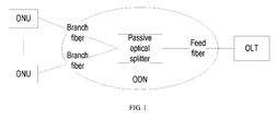
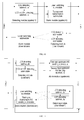
- FIG. 1 shows a structure of a traditional PON system.
- a traditional PON system is composed of an Optical Line Terminal (OLT), more than one Optical Network Unit (ONU), and an Optical Distribution Network (ODN) that connects the ONU to the OLT.
- the ODN includes a passive optical splitter for distributing optical power, a feed fiber between the passive optical splitter and the OLT, and a branch fiber between the passive optical splitter and the ONU.
- the OLT covers the ONUs that are not over 20 km away.
- FIG. 2 shows alarm links in a PON system in the prior art.
- the PON system provides three types of Operations, Administration and Maintenance (OAM) channels: embedded OAM, Physical Layer OAM (PLOAM), and Operation and Maintenance Center (OMC).
- OAM Operations, Administration and Maintenance
- BIP Bit Interleaved Parity
- RDI Remote Defect Indication
- DACT Deactivate
- the OLT is interconnected with the ONU directly through an optical splitter.
- failure detection is performed for fiber links and reported by raising alarms such as Loss of Signal (LOS) alarms and Loss of Frame (LOF) alarms; and data transmission performance is detected through BIP check and reported by raising alarms such as Signal Degrade (SD) alarms and Signal Fail (SF) alarms.
- SD Signal Degrade
- SF Signal Fail
- FIG. 3 shows a structure of an LR-PON system in the prior art.
- the LR-PON includes an OLT, a regenerator, more than one ONU, and an ODN1 and an ODN2 which are located on both sides of the regenerator.
- the ODN1 connects the regenerator to the OLT, and includes a feed fiber.
- the ODN2 connects the regenerator to the ONU, and includes: a passive optical splitter, a feed fiber between the passive optical splitter and the regenerator, and a branch fiber between the passive optical splitter and the ONU.
- a regenerator in the LR-PON system covers the ONUs up to 100 km away.
- E-R Electrical Relay
- the E-R regenerator extends the coverage of the PON and enables the OLT to cover ONUs as far as required, long-distance fiber failures may arise after the fiber transmission distance is extended from 20 km to 100 km.
- the active E-R device introduced into the PON also reduces the stability and reliability of the device in the system.
- the E-R regenerator on the feed fiber divides the fiber path into two sections, which increases the complexity of fast failure locating.
- the existing PON system provides complete monitoring and maintenance functions and specifies various alarm indications, performance events and management operations between the OLT and the ONU in detail, but such functions are applicable only to the scenarios where the OLT interworks with the ONU directly through optical signals in the traditional PON system.
- the E-R regenerator does not perform necessary monitoring or processing for the PON signals. Previous alarm indications and maintenance functions are transmitted transparently, and the failures of the intermediate nodes cannot be analyzed or located. Therefore, the existing E-R LR-PON solution does not monitor the LR-PON signals, and does not put forward various alarm indications raised in the LR-PON signal monitoring or the corresponding processing method.
- a method for managing alarms in an LR-PON system is provided in an embodiment of the present invention to monitor the LR-PON transmission quality and to process various alarm indications raised in the LR-PON signal monitoring.
- a system for managing alarms in an LR-PON system is provided in an embodiment of the present invention to monitor the LR-PON transmission quality and to process various alarm indications raised in the LR-PON signal monitoring.
- An E-R regenerator is provided in an embodiment of the present invention to monitor the LR-PON transmission quality and to raise alarms for different failures.
- a method for managing alarms in an LR-PON system includes:
- a system for managing alarms in an LR-PON system includes:
- An E-R regenerator includes:
- the alarm detection function is added in the E-R regenerator, and the detected alarm signal is transmitted to the OLT or ONU, so that the OLT can analyze, judge and locate the failure and can distinguish the alarm level, thus facilitating device maintenance.
- the OLT can analyze, judge and locate the failure and can distinguish the alarm level, thus facilitating device maintenance.
- the LR-PON transmission quality is monitored, and various alarm indications in the LR-PON signal monitoring are processed properly.
- FIG. 1 shows a structure of a traditional PON system
- FIG. 2 shows alarm links in a PON system in the prior art
- FIG. 3 shows a structure of an LR-PON system in the prior art
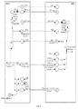
- FIG. 4 shows alarm links according to a first embodiment of the present invention
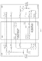
- FIG. 5 shows alarm links according to a second embodiment of the present invention
- FIG. 6 shows a structure of an upstream frame in a GPON according to an embodiment of the present invention
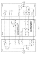
- FIG. 7 shows alarm links according to a third embodiment of the present invention.
- FIG. 8 shows an UpStream BandWidth Map (US BW Map) structure in a Physical Control Block downstream (PCBd) overhead field in a GPON according to an embodiment of the present invention
- FIG. 9 shows alarm links according to a fourth embodiment of the present invention.
- FIG. 10 shows a structure of an E-R regenerator according to the first embodiment of the present invention.
- FIG. 11 shows a structure of an E-R regenerator according to the second embodiment of the present invention.
- FIG. 12 shows a structure of an E-R regenerator according to the third embodiment of the present invention.
- FIG. 13 shows a structure of an E-R regenerator according to the fourth embodiment of the present invention.
- a method for managing alarms in an LR-PON system is provided in an embodiment of the present invention.
- the method includes:
- the method may further include:
- alarm detection is added in the E-R regenerator. After detecting an alarm, the E-R regenerator generates an alarm signal, and sends the generated alarm signal to the ONU or the OLT, so that the ONU or the OLT on the other side knows that the obtained signal fails.
- the traditional ONU and OLT need to be modified.
- Table 1 shows failure judgment and locating performed by the OLT for various alarm signals in this embodiment.
- Table 1 Alarm Type Alarm Check Point New Alarm or Existing Alarm Failure Analysis Failure Path Failure Type RDI Remote (ONU) received downstream data defect indication The ONU detects the alarm and sends it back to the OLT.
- Remote (E-R) received downstream data failure indication OLT New alarm An LOS or LOF alarm exists in the downstream data received by the E-R from the OLT. Downstream direction from the OLT to the E-R. When only failure detection is available, this alarm indicates a major alarm.
- AISd back-transmitted alarm Alarm inserted by E-R to ONU
- the ONU detects the alarm and sends it back to the OLT.
- New alarm An LOS or LOF alarm exists in the downstream data received by the E-R from the OLT. Downstream direction from the OLT to the E-R. Major alarm.
- RDId back-transmitted alarm Remote (E-R) received ONU upstream data defect indication
- the ONU detects the alarm and sends it back to the OLT.
- New alarm An LOS or LOSi or LOFi alarm exists in the upstream data received by the E-R.
- LOS Loss of signal OLT Existing alarm Loss of signal occurs in the whole upstream data stream received by the OLT. Upstream direction from the E-R to the OLT. Major alarm.
- AISu Alarm inserted by E-R to OLT OLT New alarm Loss of signal occurs in the whole upstream data stream received by the E-R.
- LOSi/ LOFi Loss of signal or frame of ONU; in the upstream direction OLT Existing alarm Loss of signal or frame occurs in the data of ONU; received in the upstream direction by the OLT. Upstream direction from the E-R to the OLT.
- AISi Alarm inserted by E-R to ONU i OLT New alarm Loss of signal and loss of frame occur in the data of Upstream received in the received in the upstream direction by the E-R. direction from ONU i to the E-R. Major alarm.
- the OLT After receiving the alarm signal, the OLT determines which side of the fiber path fails and the type of the failure according to the method of failure judgment and locating shown in Table 1.
- Table 2 shows how an OLT processes a new alarm signal
- Table 3 shows how an ONU processes a new alarm signal according to an embodiment of the present invention.
- Table 2 Alarm Type Detection Conditions Actions Cancellation Conditions AISu Alarm frame inserted for the whole upstream data stream A data stream compliant with the AISu alarm frame format is detected. Suppress the LOSi, LOFi, and AISi alarms. frame A data stream incompliant with the AISu alarm format is detected. AISi Alarm frame ONU i For the data frame of ONU i , a data stream alarm frame format is detected. Suppress the LOFi alarm.
- RDIu Remote defect indication
- the value of the physical overhead area RDIu of the upstream data frame of the ONU is 1, it indicates that a defect exists in the data sent by the OLT to the E-R regenerator in the downstream direction. Recover the downstream interface processing unit of the OLT.
- the value of RDIu is 0.
- Table 3 Alarm Type Detection Condition Actions Conditions Cancellation AISd Alarm inserted for all ONUs in the downstream direction A data stream compliant with the AISd alarm frame format is detected. It indicates that the failure occurs on the path from the OLT to the E-R regenerator in the downstream direction. Suppress the LOF alarm.
- RDId Remote defect indication When the value of the physical overhead area RDId of the downstream data frame of the OLT is 1, it indicates that a defect data sent by exist in the data sent by the ONU to the E-R unit regenerator in the upstream direction. Recover the Recover the upstream interface processing unit of the of the ONU. The value of RDId The value of RDId is 0.
- FIG. 4 shows alarm links according to the first embodiment of the present invention.
- alarm detection functions are added only to the E-R generator, and the ONU and the OLT remain unchanged.
- the E-R regenerator After detecting an LOS or LOF alarm, the E-R regenerator switches off the transmitting laser in the downstream direction, so that the ONU detects the LOS alarm in the downstream direction.
- the subsequent processing is the same as that in the prior art; that is, the ONU determines that an LOS failure occurs on the downstream path from the E-R regenerator to the ONU.
- the E-R regenerator switches on the transmitting laser in the downstream direction again.
- the E-R regenerator After detecting the LOS alarm, the E-R regenerator switches off the transmitting laser in the upstream direction, so that the OLT detects the LOS alarm in the upstream direction.
- the subsequent processing is the same as that in the prior art. After knowing that the LOS alarm is cleared, the E-R regenerator switches on the transmitting laser in the upstream direction again.
- the E-R regenerator performs detection and frame alignment for the electrical signal which is obtained through optical-to-electrical (O/E) conversion of the PON upstream optical signal from the ONU, and judges whether LOS or LOF occurs in the upstream data sent by the ONU. If LOS or LOF occurs in the upstream data sent by the ONU, the E-R regenerator transmits the LOSi alarm to the OLT transparently so that the OLT detects the LOSi alarm. The subsequent processing on the OLT is the same as that in the prior art.
- O/E optical-to-electrical
- the solution under the present invention is simple, and is compatible with the existing functions of the ONU and the OLT in the prior art.
- FIG. 5 shows alarm links according to the second embodiment of the present invention.
- the features that make this embodiment different from the first embodiment are as follows: An alarm back-transmission function is added to the E-R regenerator; the OLT can detect and process three additional types of alarms to facilitate failure judgment and locating; and the ONU remains unchanged.
- the E-R regenerator After detecting the LOS and LOF alarms, the E-R regenerator switches off the transmitting laser in the downstream direction, the details of which are the same as those of the first embodiment and are provided further.
- the E-R regenerator After detecting the LOS and LOF alarms, the E-R regenerator sends the set third-type downstream Alarm Indication Signal (AIS) back to the OLT.
- AIS Alarm Indication Signal
- the third-type downstream AIS is an RDIu alarm.
- the OLT determines that a failure leading to LOS or LOF occurs on the downstream path from the OLT to the E-R regenerator. As shown in Table 2, a recovery operation is performed for the downstream interface processing unit of the OLT.
- the E-R regenerator may send back the RDIu through idle bits in a PON upstream frame.
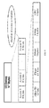
- FIG. 6 shows a structure of an upstream frame according to a GPON in an embodiment of the present invention.
- bit 0 in the real time state indication (Ind) field in the Physical Layer Overhead upstream (PLOu) field is idle, and may serve as a back-transmission indication of the RDIu alarm.
- Table 4 shows functions of the bits in the Ind field in the PLOu field of the GPON upstream frame.
- the E-R regenerator After detecting the LOS alarm, the E-R regenerator inserts the set first-type upstream AIS to the OLT.
- the first-type upstream AIS is an AISu alarm.
- the OLT determines that a failure leading to LOS occurs on the upstream path from the ONU to the E-R regenerator. As shown in Table 2, the OLT suppresses the LOSi, LOFi, and AISi alarms.
- the E-R regenerator inserts the set second-type upstream AIS to the OLT.
- the second-type upstream AIS is an AISi alarm.
- the OLT determines that a failure leading to LOS or LOF in the upstream data of the ONU occurs on the upstream path from ONU i to the E-R regenerator. As shown in Table 2, the OLT suppresses the LOFi alarm.
- the inserted AISu and AISi alarms are "alarm frames".
- Their frame header is similar to the pattern format of the upstream frame delimiter "a byte” and "b byte” of the GPON.
- a simple mode is to fill the upstream data with "a byte” and "b byte” to make a new alarm signal without frame boundary, which facilitates the OLT to detect, distinguish and suppress the LOS, LOSi, and LOFi alarms.
- FIG. 7 shows alarm links according to the third embodiment of the present invention.
- the features that make this embodiment different from the second embodiment are as follows: One more alarm back-transmission function is added to the E-R regenerator; and the ONU can detect and process two additional types of alarms.
- the E-R regenerator After detecting the LOS and LOF alarms, the E-R regenerator does not switch off the transmitting laser in the downstream direction, but inserts the first-type downstream AIS to the ONU.
- the first-type downstream AIS is an AISd alarm.
- the ONU After receiving the AISd alarm, the ONU determines that a failure leading to LOS or LOF occurs on the downstream path from the OLT to the E-R regenerator. As shown in Table 3, the ONU suppresses the LOF alarm.
- the inserted AISd alarm is an "alarm frame". Its frame header is similar to the pattern format of the downstream frame delimiter "PSync" of the GPON.
- a simple mode is to fill the downstream data with "PSync" characters to make a new alarm signal without frame boundary, which facilitates the downstream ONU to detect, distinguish and suppress the LOS and LOF alarms.
- the E-R regenerator after detecting the LOS alarm of the whole upstream data stream, the E-R regenerator sends the set third-type upstream AIS back to all ONUs, where the third-type upstream AIS is an RDId alarm. After detecting the LOSi and LOFi alarms of the upstream data of the ONU, the E-R regenerator sends the set third-type upstream AIS back to the corresponding ONU.
- the third-type upstream AIS is an RDIdi alarm.
- the ONU After receiving the RDId alarm, the ONU determines that a failure occurs on the upstream path from the ONU to the E-R regenerator and this failure leads to LOS of the whole data stream or leads to LOS or LOF in the upstream data sent by the corresponding ONU.
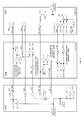
- FIG. 8 shows an US BW Map structure in a PCBd overhead field in a GPON in an embodiment of the present invention.
- the US BW Map in the PCBd overhead field is composed of 8-byte vector groups. Each vector group has a flag field, and the functions of the bits in the flag field are described in Table 5.
- bits 0-6 are idle. One of the bits may be selected to indicate whether to allow the ONU to process new alarms, and another bit is selected as an RDId back-transmitted alarm.
- FIG. 9 shows alarm links in the fourth embodiment of the present invention.
- the features that make this embodiment different from the third embodiment are: The E-R regenerator, the OLT and the ONU are modified, and performance monitoring of data transmission quality and the method for processing the corresponding detected alarms are added.
- the E-R regenerator if the E-R regenerator does not detect any LOS or LOF alarm, the E-R regenerator performs data check for the determined downstream data frame, measures the Bit Error Rate (BER) according to the data check result, and judges whether the BER is higher than the preset BER threshold. If the BER is higher than the preset threshold, the E-R regenerator sends the set third-type downstream AIS to the OLT.
- the third-type downstream AIS is an RDIu alarm.
- the ONU after receiving the AISd alarm, the ONU sends the AISd alarm back to the OLT.
- the OLT determines that a failure leading to LOS or LOF occurs on the downstream path from the OLT to the E-R regenerator.
- the E-R regenerator if the E-R regenerator does not detect any LOS, LOSi or LOFi alarm, the E-R regenerator performs data check for the determined upstream data frame, measures the BER according to the data check result, and judges whether the BER is higher than the preset BER threshold. If the BER is higher than the preset threshold, the E-R regenerator sends the third-type upstream AIS to the ONU.
- the third-type upstream AIS is an RDId alarm.
- the ONU determines that a failure leading to increase of the BER of the data frame occurs on the upstream path from the ONU to the E-R regenerator, and attempts to recover the upstream interface processing unit of the ONU.
- the ONU sends the received RDId alarm back to the OLT.
- the OLT determines that a failure leading to increase of the BER of the data frame occurs on the upstream path from the ONU to the E-R regenerator.
- the ONU may send the AISd alarm and the RDId alarm back to the OLT through a PLOAM message in two modes:
- the first mode is to define a new PLOAM message.
- Table 6 shows a newly defined message for sending back the AISd alarm and the RDId alarm.
- Table 6 Remote Alarm and Defect Indication Message Byte Content Description 1 ONU-ID This byte specifies an ONU. 2 00001010 This byte indicates a message type, and is defined as a "remote alarm and defect indication message".
- the existing GPON has specified nine types of upstream PLAOM messages. The value of this byte needs to be greater than 9, for example, "00001010".
- the second mode is to use the existing PLOAM message such as an REI message, and use the idle byte in the message to define the AISd alarm and the RDId alarm.
- Table 7 shows the newly defined AISd alarm and RDId alarm in an REI message.
- Table 7 Remote Alarm and Defect Indication Message Byte Content Description 1 ONU-ID This byte specifies an ONU. 2 00001000 This byte indicates a message type. In the existing GPON, this type is defined as a "remote error indication message". In the LR-PON application, this byte is defined as a "remote alarm and defect indication message”. 3 Error block count 1 Highest 8 bits of the 32-bit REI counter.
- the ONU detects an RDId, it indicates that the transmission performance of the upstream data is degraded. Therefore, even if the data is transmitted through a PLOAM message which provides CRC-8 check, the PLOAM message is preferably sent repeatedly (for example, for three consecutive times) to resist errors and to improve reliability.
- the foregoing four embodiments meet different cost requirements and application scenarios, and exert different impacts on the existing functions of the ONU and the OLT.
- the first embodiment is the simplest and the most cost-efficient. It exerts no impact on the existing functions of the ONU or the OLT in the prior art, involves no modification to the existing ONU or OLT, and is compatible with the existing devices.
- the second embodiment involves a little modification to the existing OLT, and supports a few new types of alarms. It analyzes, judges and locates the main failures on the path between both sides of the E-R in the LR-PON, and on the path between the ONU and the OLT; and at the same time, it is compatible with the existing ONU.
- the third and the fourth embodiments involve a little modification to the existing ONU and OLT.
- the third embodiment considers only the failure detection for the PON signals in the E-R, and does not consider data transmission performance monitoring.
- the fourth embodiment is the most comprehensive. It adds only three types of alarm signals to the OLT and adds only two types of alarm signals to the ONU, but ensures that the OLT can analyze various alarm signals, locate failures, and implement alarm management and maintenance for the E-R.
- a system for managing alarms in an LR-PON system is provided in an embodiment of the present invention.
- the system includes:
- the E-R regenerator includes:
- the E-R regenerator for managing alarms in an LR-PON system under the present invention is detailed below with reference to exemplary embodiments.
- FIG. 10 shows a structure of an E-R regenerator according to the first embodiment of the present invention.
- the detecting module includes:
- the alarm module includes:
- the detecting module may further include:
- the laser switching submodule is further adapted to switch off the transmitting laser in the downstream direction according to the received LOF notification.
- the detecting module includes:
- the alarm module includes:
- the detecting module may further include:
- the alarm module may further include:
- the E-R regenerator in this embodiment implements alarm management in the LR-PON system without making any modification to the existing ONU or OLT.
- FIG. 11 shows a structure of an E-R regenerator in the second embodiment of the present invention.
- the alarm module in this embodiment may further include:
- the alarm module in this embodiment may include:
- the E-R regenerator disclosed in this embodiment adds three types of AIS and involves certain modification to the existing OLT, so that the OLT can judge, identify and process the received AIS.
- FIG. 12 shows a structure of an E-R regenerator according to the third embodiment of the present invention.
- the detecting module may include:
- the alarm module may include:
- the alarm module in this embodiment may further include:
- the E-R regenerator disclosed in this embodiment adds five types of AIS and involves certain modification to the existing OLT and ONU, so that the OLT and ONU can judge, identify and process the received AIS.
- FIG. 13 shows a structure of an E-R regenerator in the fourth embodiment of the present invention.
- the detecting module in this embodiment may further include:
- the detecting module in this embodiment may further include:
- the E-R regenerator disclosed in this embodiment adds five types of AIS, performs failure detection and performance monitoring, and involves certain modification to the existing OLT and ONU, so that the OLT and ONU can judge, identify and process the received AIS.
- the method, system and apparatus for managing alarms in an LR-PON system under the present invention provide a whole set of alarm management links, and implement main alarm detection and management functions with little modification to the existing ONU and OLT, thus facilitating detection, locating and processing of failures, and saving costs of operation and maintenance.
- different alarm link solutions are disclosed herein to meet different requirements and application scenarios.
- the alarm links disclosed herein involve little technical difficulty and are easily practicable and cost-efficient, and can satisfy the requirements of the service provider shortly.
Landscapes
- Engineering & Computer Science (AREA)
- Computer Networks & Wireless Communication (AREA)
- Signal Processing (AREA)
- Physics & Mathematics (AREA)
- Electromagnetism (AREA)
- Computing Systems (AREA)
- Optical Communication System (AREA)
- Small-Scale Networks (AREA)
Applications Claiming Priority (2)
| Application Number | Priority Date | Filing Date | Title |
|---|---|---|---|
| CN200710163635.3A CN101414932B (zh) | 2007-10-15 | 2007-10-15 | 长距离无源光网络系统中告警管理的方法、系统及装置 |
| PCT/CN2008/072461 WO2009052721A1 (en) | 2007-10-15 | 2008-09-23 | Method, system and device for alarm management in long reach passive optical network system |
Publications (2)
| Publication Number | Publication Date |
|---|---|
| EP2109252A1 true EP2109252A1 (de) | 2009-10-14 |
| EP2109252A4 EP2109252A4 (de) | 2010-01-13 |
Family
ID=40579071
Family Applications (1)
| Application Number | Title | Priority Date | Filing Date |
|---|---|---|---|
| EP08800950A Withdrawn EP2109252A4 (de) | 2007-10-15 | 2008-09-23 | Verfahren, system und vorrichtung zum alarm-management in einem langreichweitigem passiven optischen netzsystem |
Country Status (4)
| Country | Link |
|---|---|
| US (1) | US8285139B2 (de) |
| EP (1) | EP2109252A4 (de) |
| CN (1) | CN101414932B (de) |
| WO (1) | WO2009052721A1 (de) |
Cited By (3)
| Publication number | Priority date | Publication date | Assignee | Title |
|---|---|---|---|---|
| EP2357738A4 (de) * | 2008-10-31 | 2012-03-21 | Huawei Tech Co Ltd | Informationstransfer- und empfangsverfahren, system und einrichtung |
| WO2016124044A1 (zh) * | 2015-02-05 | 2016-08-11 | 中兴通讯股份有限公司 | 无源光网络设备告警信息处理方法及光线路终端 |
| WO2020242519A1 (en) * | 2019-05-30 | 2020-12-03 | Google Llc | In-field calibration of laser transmitter |
Families Citing this family (25)
| Publication number | Priority date | Publication date | Assignee | Title |
|---|---|---|---|---|
| CN102148682B (zh) * | 2010-02-08 | 2016-02-10 | 中兴通讯股份有限公司 | 一种对发光异常光网络单元正确定位的方法及系统 |
| CN101820558B (zh) * | 2010-04-23 | 2013-01-02 | 烽火通信科技股份有限公司 | 一种无源光网络检测长发光onu的方法 |
| CN102281100B (zh) * | 2010-06-12 | 2016-02-24 | 中兴通讯股份有限公司 | 长距无源光网络中实现光程检测的方法及装置 |
| US9369207B2 (en) * | 2010-11-15 | 2016-06-14 | Alcatel Lucent | Apparatus and method for two-stage optical network |
| CN102611575B (zh) * | 2012-02-24 | 2015-12-02 | 瑞斯康达科技发展股份有限公司 | 一种控制onu设备指示灯显示的方法、设备及系统 |
| CN102664672B (zh) * | 2012-04-20 | 2015-02-18 | 南京矿通科技有限公司 | 具有自动断尾和恢复功能的双向中继器及其控制方法 |
| US9602196B2 (en) * | 2012-06-20 | 2017-03-21 | Telefonaktiebolaget L M Ericsson | Devices and methods for flow control of messages in a passive optical network (PON) and methods therein |
| US8948587B2 (en) * | 2012-06-27 | 2015-02-03 | Centurylink Intellectual Property Llc | Use of dying gasp to locate faults in communications networks |
| CN102946321B (zh) * | 2012-10-16 | 2016-06-29 | 杭州华三通信技术有限公司 | 一种基于irf网络的故障处理方法和设备 |
| CN105659512B (zh) * | 2013-10-25 | 2018-01-02 | 日本电信电话株式会社 | 光通信系统和光通信异常恢复方法 |
| CN104811240B (zh) * | 2014-01-28 | 2017-09-01 | 中国电信股份有限公司 | 检测pon系统中异常发光onu的方法与olt |
| CN105306135B (zh) * | 2014-07-16 | 2018-03-23 | 中兴通讯股份有限公司 | 链路轮询检测方法及装置 |
| CN105375979B (zh) * | 2015-11-19 | 2018-05-18 | 上海斐讯数据通信技术有限公司 | 一种无源光网络中排查异常光网络单元的方法和装置 |
| US10243687B2 (en) * | 2016-11-17 | 2019-03-26 | Google Llc | Optical network unit wavelength tuning |
| CN109120338B (zh) * | 2017-06-26 | 2020-11-06 | 中国移动通信集团安徽有限公司 | 网络故障定位方法、装置、设备和介质 |
| CN107465540B (zh) * | 2017-07-26 | 2020-10-16 | 烽火通信科技股份有限公司 | Gpon拉远系统、管理方法及存储介质 |
| US11206174B2 (en) * | 2018-10-31 | 2021-12-21 | Nxp B.V. | Method and system for diagnosis of failures in a communications network |
| CN112822229B (zh) * | 2019-11-18 | 2022-10-14 | 中国电信股份有限公司 | Onu故障处理方法、onu、pon系统以及存储介质 |
| CN113765725A (zh) * | 2020-06-02 | 2021-12-07 | 华为技术有限公司 | 一种告警处理方法及装置 |
| CN111935565A (zh) * | 2020-07-16 | 2020-11-13 | 苏州伏特通信科技有限公司 | 一种通信传输设备故障报警系统 |
| CN113055092B (zh) * | 2021-03-17 | 2022-07-12 | 卡斯柯信号有限公司 | 一种提高既有信号设备通信传输安全性的设备和方法 |
| CN113727223B (zh) * | 2021-08-18 | 2023-11-03 | 烽火通信科技股份有限公司 | 一种上行数据发送方法、异常发光检测方法、设备及系统 |
| CN116744155B (zh) * | 2022-03-04 | 2024-12-20 | 中兴通讯股份有限公司 | 一种全光网络节能处理方法及装置 |
| US12009978B2 (en) * | 2022-07-01 | 2024-06-11 | Arris Enterprises Llc | NETCONF based alarm management for passive optical network |
| CN118138126A (zh) * | 2022-12-02 | 2024-06-04 | 中国移动通信有限公司研究院 | 一种光网络故障管理方法、装置及介质 |
Family Cites Families (14)
| Publication number | Priority date | Publication date | Assignee | Title |
|---|---|---|---|---|
| US6023467A (en) * | 1997-05-08 | 2000-02-08 | Ericsson, Inc. | Operations and maintenance data flows over a point to multipoint broadband access network |
| WO2001035581A1 (fr) * | 1999-11-10 | 2001-05-17 | Fujitsu Limited | Appareil et systeme de communication optique |
| US6898206B2 (en) * | 2001-06-06 | 2005-05-24 | Advanced Fibre Access Corporation | Wavelength division multiplexed (WDM) ring passive optical network (PON) with route protection for replacement of splitter based passive optical networks |
| ATE278274T1 (de) * | 2002-06-24 | 2004-10-15 | Cit Alcatel | Vorrichtung für ein passives optisches netzwerk |
| JP4920888B2 (ja) * | 2002-12-16 | 2012-04-18 | ピーエムシー−シエラ イスラエル リミテッド | イーサネット(登録商標)フレーム前方誤り訂正の初期化及びオートネゴシエーションの方法 |
| CN1258270C (zh) * | 2003-05-29 | 2006-05-31 | 上海交通大学 | 无源光网络保护方法 |
| KR100547709B1 (ko) | 2003-07-07 | 2006-01-31 | 삼성전자주식회사 | 자기 치유 파장분할다중방식 수동형 광 가입자망 |
| CN100388742C (zh) * | 2004-07-22 | 2008-05-14 | 烽火通信科技股份有限公司 | 以太网无源光网络的流量控制方法和该方法所使用的装置 |
| WO2007010518A1 (en) * | 2005-07-18 | 2007-01-25 | Passave Ltd. | Method and system for passive optical network diagnostics |
| CN101047442B (zh) * | 2006-04-02 | 2012-05-30 | 华为技术有限公司 | 一种无源光网络的维护方法及其系统 |
| JP4827651B2 (ja) | 2006-08-10 | 2011-11-30 | 富士通株式会社 | 光伝送方法及び装置 |
| CN101222278B (zh) * | 2007-01-12 | 2012-05-09 | 中兴通讯股份有限公司 | 光网络单元上行时隙冲突的检测方法和系统 |
| CN101399614B (zh) * | 2007-09-26 | 2012-10-03 | 华为技术有限公司 | 一种长距离无源光网络的保护方法、系统和设备 |
| US8611740B2 (en) * | 2008-02-22 | 2013-12-17 | Motorola Mobility Llc | System and method for protecting an extended passive optical network |
-
2007
- 2007-10-15 CN CN200710163635.3A patent/CN101414932B/zh not_active Expired - Fee Related
-
2008
- 2008-09-23 WO PCT/CN2008/072461 patent/WO2009052721A1/zh not_active Ceased
- 2008-09-23 EP EP08800950A patent/EP2109252A4/de not_active Withdrawn
-
2009
- 2009-10-23 US US12/605,067 patent/US8285139B2/en not_active Expired - Fee Related
Cited By (4)
| Publication number | Priority date | Publication date | Assignee | Title |
|---|---|---|---|---|
| EP2357738A4 (de) * | 2008-10-31 | 2012-03-21 | Huawei Tech Co Ltd | Informationstransfer- und empfangsverfahren, system und einrichtung |
| US8559819B2 (en) | 2008-10-31 | 2013-10-15 | Huawei Technologies Co., Ltd. | Information transfer and receiving method, system, and device |
| WO2016124044A1 (zh) * | 2015-02-05 | 2016-08-11 | 中兴通讯股份有限公司 | 无源光网络设备告警信息处理方法及光线路终端 |
| WO2020242519A1 (en) * | 2019-05-30 | 2020-12-03 | Google Llc | In-field calibration of laser transmitter |
Also Published As
| Publication number | Publication date |
|---|---|
| US8285139B2 (en) | 2012-10-09 |
| CN101414932A (zh) | 2009-04-22 |
| US20100040363A1 (en) | 2010-02-18 |
| CN101414932B (zh) | 2012-09-05 |
| EP2109252A4 (de) | 2010-01-13 |
| WO2009052721A1 (en) | 2009-04-30 |
Similar Documents
| Publication | Publication Date | Title |
|---|---|---|
| US8285139B2 (en) | Method, system, and apparatus for managing alarms in long-reach passive optical network system | |
| US8879905B2 (en) | Performance monitoring in passive optical networks | |
| KR100320700B1 (ko) | Ip 패킷 통신 장치 | |
| EP0702870B1 (de) | Funktionsuberwachung und fehlerabhangige abschaltung in einem punkt-zu-mehrpunkt kommunikationsnetzwerk | |
| EP2200191B1 (de) | Verfahren, system und vorrichtung zum schutz in einem passiven optischen netzwerk mit grosser reichweite | |
| US8335439B2 (en) | Method of ethernet frame forward error correction initialization and auto-negotiation | |
| EP2413562B1 (de) | Verfahren und passives optisches netzwerksystem zur verwaltung von uplink-burst-overhead-parametern | |
| EP2434666B1 (de) | Verfahren, vorrichtung und system zur erkennung von verknüpfungsfehlern | |
| CN101674499A (zh) | 无源光网系统及其故障确定方法 | |
| US20080298803A1 (en) | System and method for protection of point to multipoint passive optical network | |
| CN101369846A (zh) | 一种无源光网络信号监控方法及电中继再生器 | |
| KR101821814B1 (ko) | Wdm-tdm 수동형 광 가입자망 원격 종단 단말 및 wdm-tdm 수동형 광 가입자망 링크 보호 시스템 | |
| EP2154797A1 (de) | Fehlerdetektionsverfahren, -system und -vorrichtung für passives optisches netzwerksystem | |
| US20050147410A1 (en) | Method and system configured for providing passive optical network fiber protection | |
| US20070133564A1 (en) | Method for propagating maintenance signal in VPWS network using SDH/SONET | |
| CN100421397C (zh) | 一种光突发交换网络性能及故障监测方法 | |
| US20090052891A1 (en) | Method and Apparatus for Reducing Error Rate During Data Transmission in an Optical Communications Network | |
| CN116996366A (zh) | 用于omci通道的通信方法及系统 | |
| HK1161775B (en) | Performance monitoring in passive optical networks | |
| KR20090125957A (ko) | 이더넷 수동광분기망에서 장애 발생 검출 방법 및 시스템 | |
| CN102377507A (zh) | 基于gpon的光桥接器设备及其测距方法 |
Legal Events
| Date | Code | Title | Description |
|---|---|---|---|
| PUAI | Public reference made under article 153(3) epc to a published international application that has entered the european phase |
Free format text: ORIGINAL CODE: 0009012 |
|
| 17P | Request for examination filed |
Effective date: 20090810 |
|
| AK | Designated contracting states |
Kind code of ref document: A1 Designated state(s): AT BE BG CH CY CZ DE DK EE ES FI FR GB GR HR HU IE IS IT LI LT LU LV MC MT NL NO PL PT RO SE SI SK TR |
|
| RIC1 | Information provided on ipc code assigned before grant |
Ipc: H04J 3/16 20060101AFI20091201BHEP Ipc: H04J 3/14 20060101ALI20091201BHEP Ipc: H04L 12/24 20060101ALN20091201BHEP Ipc: H04B 10/08 20060101ALI20091201BHEP |
|
| A4 | Supplementary search report drawn up and despatched |
Effective date: 20091210 |
|
| 17Q | First examination report despatched |
Effective date: 20100325 |
|
| DAX | Request for extension of the european patent (deleted) | ||
| STAA | Information on the status of an ep patent application or granted ep patent |
Free format text: STATUS: THE APPLICATION IS DEEMED TO BE WITHDRAWN |
|
| 18D | Application deemed to be withdrawn |
Effective date: 20140121 |