EP2109560B1 - Parkbremsenanordnung für bremssystem eines schienenfahrzeuges - Google Patents
Parkbremsenanordnung für bremssystem eines schienenfahrzeuges Download PDFInfo
- Publication number
- EP2109560B1 EP2109560B1 EP08728548.2A EP08728548A EP2109560B1 EP 2109560 B1 EP2109560 B1 EP 2109560B1 EP 08728548 A EP08728548 A EP 08728548A EP 2109560 B1 EP2109560 B1 EP 2109560B1
- Authority
- EP
- European Patent Office
- Prior art keywords
- parking brake
- fluid pressure
- brake
- assembly
- housing
- Prior art date
- Legal status (The legal status is an assumption and is not a legal conclusion. Google has not performed a legal analysis and makes no representation as to the accuracy of the status listed.)
- Not-in-force
Links
- 239000012530 fluid Substances 0.000 claims description 119
- 238000004891 communication Methods 0.000 claims description 22
- 230000007246 mechanism Effects 0.000 claims description 8
- 230000002093 peripheral effect Effects 0.000 claims description 8
- 230000009467 reduction Effects 0.000 claims description 8
- 230000006835 compression Effects 0.000 claims description 6
- 238000007906 compression Methods 0.000 claims description 6
- 125000006850 spacer group Chemical group 0.000 claims description 2
- 230000008901 benefit Effects 0.000 description 3
- 238000010276 construction Methods 0.000 description 3
- 230000000694 effects Effects 0.000 description 3
- 230000007423 decrease Effects 0.000 description 2
- 238000010586 diagram Methods 0.000 description 2
- 230000003137 locomotive effect Effects 0.000 description 2
- 238000004804 winding Methods 0.000 description 2
- 230000004308 accommodation Effects 0.000 description 1
- 230000009471 action Effects 0.000 description 1
- 230000003213 activating effect Effects 0.000 description 1
- 230000000712 assembly Effects 0.000 description 1
- 238000000429 assembly Methods 0.000 description 1
- 238000005452 bending Methods 0.000 description 1
- 230000001419 dependent effect Effects 0.000 description 1
- 230000001627 detrimental effect Effects 0.000 description 1
- 230000014759 maintenance of location Effects 0.000 description 1
- 238000000034 method Methods 0.000 description 1
- 238000005086 pumping Methods 0.000 description 1
- 230000004044 response Effects 0.000 description 1
- 239000011435 rock Substances 0.000 description 1
Images




Classifications
-
- B—PERFORMING OPERATIONS; TRANSPORTING
- B60—VEHICLES IN GENERAL
- B60T—VEHICLE BRAKE CONTROL SYSTEMS OR PARTS THEREOF; BRAKE CONTROL SYSTEMS OR PARTS THEREOF, IN GENERAL; ARRANGEMENT OF BRAKING ELEMENTS ON VEHICLES IN GENERAL; PORTABLE DEVICES FOR PREVENTING UNWANTED MOVEMENT OF VEHICLES; VEHICLE MODIFICATIONS TO FACILITATE COOLING OF BRAKES
- B60T17/00—Component parts, details, or accessories of power brake systems not covered by groups B60T8/00, B60T13/00 or B60T15/00, or presenting other characteristic features
- B60T17/08—Brake cylinders other than ultimate actuators
- B60T17/085—Spring loaded brake actuators
- B60T17/086—Spring loaded brake actuators with emergency release device
-
- B—PERFORMING OPERATIONS; TRANSPORTING
- B60—VEHICLES IN GENERAL
- B60T—VEHICLE BRAKE CONTROL SYSTEMS OR PARTS THEREOF; BRAKE CONTROL SYSTEMS OR PARTS THEREOF, IN GENERAL; ARRANGEMENT OF BRAKING ELEMENTS ON VEHICLES IN GENERAL; PORTABLE DEVICES FOR PREVENTING UNWANTED MOVEMENT OF VEHICLES; VEHICLE MODIFICATIONS TO FACILITATE COOLING OF BRAKES
- B60T13/00—Transmitting braking action from initiating means to ultimate brake actuator with power assistance or drive; Brake systems incorporating such transmitting means, e.g. air-pressure brake systems
- B60T13/10—Transmitting braking action from initiating means to ultimate brake actuator with power assistance or drive; Brake systems incorporating such transmitting means, e.g. air-pressure brake systems with fluid assistance, drive, or release
- B60T13/24—Transmitting braking action from initiating means to ultimate brake actuator with power assistance or drive; Brake systems incorporating such transmitting means, e.g. air-pressure brake systems with fluid assistance, drive, or release the fluid being gaseous
-
- B—PERFORMING OPERATIONS; TRANSPORTING
- B60—VEHICLES IN GENERAL
- B60T—VEHICLE BRAKE CONTROL SYSTEMS OR PARTS THEREOF; BRAKE CONTROL SYSTEMS OR PARTS THEREOF, IN GENERAL; ARRANGEMENT OF BRAKING ELEMENTS ON VEHICLES IN GENERAL; PORTABLE DEVICES FOR PREVENTING UNWANTED MOVEMENT OF VEHICLES; VEHICLE MODIFICATIONS TO FACILITATE COOLING OF BRAKES
- B60T15/00—Construction arrangement, or operation of valves incorporated in power brake systems and not covered by groups B60T11/00 or B60T13/00
- B60T15/02—Application and release valves
- B60T15/021—Railway control or brake valves
Definitions
- the present invention relates, in general, to railway vehicle braking systems and, more particularly, this invention relates to a parking brake assembly for use in a railway vehicle braking system and, still more particularly, the present invention relates to a parking brake assembly for use in a railway vehicle truck mounted brake rigging.
- the brake system used on the railway cars employs a plurality of force transmitting members to convert supply of the pneumatic fluid pressure from the brake pipe into a mechanical force to apply and bias one or more brake shoes against the tread of one or more wheels of the railway car.
- a typical railway car hand brake system normally consists of an apparatus for manually applying and biasing one or more brake shoes against the tread of one or more wheels of the railway car by either turning a hand wheel or pumping a ratchet handle on a hand brake mechanism attached to the railway car.
- an operator it has been known for an operator to improperly apply the hand brake causing undesirable movement of the railway cars.
- the present invention provides a parking brake actuator for a railway vehicle brake rigging being in fluid communication with a fluid pressure carrying brake pipe of the railway vehicle.
- the brake rigging has at least a push rod mounted for movement therewithin.
- the push rod is responsive to a reduction of the fluid pressure in the brake pipe to move in a first direction causing the brake rigging to apply brakes and is responsive to an increase of the fluid pressure in the brake pipe to move in an opposed second direction causing the brake rigging to release brakes.
- the parking brake actuator includes a hollow housing engageable with a predetermined portion of the brake rigging.
- the housing has a first end and an opposed second end. The first end has means for mounting the parking brake actuator to a portion of the brake rigging.
- a piston assembly is mounted for a longitudinal movement within the housing and divides the housing into a pressurized portion disposed intermediate the first end of the housing and a first end of the piston assembly and a non-pressurized portion disposed adjacent the second end of the housing.
- a piston rod is secured at a first end thereof to a second end of the piston assembly and is capable of extending through the axial opening in the second end of the housing responsive to the supply of fluid pressure.
- the piston rod is securable at a second end thereof to a first end of the push rod, whereby the piston rod and the piston assembly move longitudinally with the push rod in the first and second directions.
- a means is provided for preventing rotation of the piston rod during its longitudinal movement within the housing.
- a spring member is disposed in the non-pressurized portion of the housing and is caged between an inner surface of the second end of the housing and the second end of the piston assembly.
- the spring member is capable of exerting a force against the piston assembly upon release of the spring member responsive to a loss of the fluid pressure in the pressurized portion of the housing, causing the longitudinal movement of the piston assembly within the housing in the second direction to accordingly retract the piston rod thereinto.
- a fluid communication means is provided in a fluid communication with the pressurized portion of the housing and with the brake pipe for supplying the fluid pressure to the parking brake actuator during brake application of the railway vehicle brake rigging resulting in the longitudinal movement of the piston assembly and the piston rod in the first direction and in compression of the spring member.
- the fluid communication means is also provided for evacuating the fluid pressure from the pressurized portion of the housing during brake release resulting in the longitudinal movement of the piston assembly and the piston rod in the second direction due to the force exerted by the released spring member.
- There is a first elongated thread which is formed on at least a portion of the piston rod movable through the non-pressurized portion of the housing.
- a ratchet is mounted within the non-pressurized portion of the housing for rotation about a longitudinal axis of the piston rod.
- An aperture is axially formed through the ratchet.
- a second thread is formed on a surface of the axial aperture for operable engagement with the first thread.
- a shaft is mounted for rotation in a spaced relationship with the ratchet.
- Rotational axis of the shaft is substantially parallel to a rotational axis of the ratchet.
- the shaft has a first end thereof disposed within the non-pressurized portion of the housing and has a second end thereof extending through an aperture formed through the second end of the housing past an outer surface thereof.
- a holding pawl is disposed within the non-pressurized portion of the housing and is secured to the shaft for rotation therewith. The holding pawl is rotateable in a first rotational direction for engagement with the ratchet teeth when a first rotational force is applied to the second end of the shaft due to the fluid pressure in the brake pipe being reduced to a predetermined level, the engagement preventing movement of the push rod in the second direction.
- the holding pawl is rotateable in a second rotational direction for disengaging the ratchet teeth and permitting the push rod to move in the second direction when a second rotational force is applied to at least one of the second end of the shaft and the holding pawl due to the increase of the fluid pressure in the brake pipe.
- a manual release assembly for a parking brake assembly in a railway car.
- the parking brake assembly at least includes a push rod mounted for reciprocal motion within the brake rigging and a pneumatic fluid-pressure-operable brake actuator connected to the push rod and responsive to a reduction of pneumatic fluid pressure in a brake pipe to longitudinally move the push rod in a first direction in order to apply a braking force and maintain the push rod to continue to apply the braking force, the parking brake assembly responsive to an increase of the pneumatic fluid pressure supply in the brake pipe to longitudinally move the push rod in a second direction to release the braking force.
- the manual release includes a bracket secured to a rigid member of the railway car. An L-shaped slot is formed in the bracket.
- An elongated link member has a first end thereof passed through the L-shaped slot and extending outwardly from the bracket. There is means for connecting a second end of the link member to the brake actuator.
- a grip member is disposed on and secured to the first end of the elongated link member. The grip member is manually operable to move the link member from a first position enabling application of the parking brake assembly into a second position enabling release of an applied parking brake assembly.
- a bias means is provided and is engageable with the elongated link member and with the bracket for returning it into the first position upon release of the grip member.
- a valve means mounted within a fluid communication means connecting the parking brake assembly to a brake pipe.
- the valve means is operable in a first position for supplying the fluid pressure to the parking brake assembly when the fluid pressure in the brake pipe is maintained above a predetermined level.
- the valve means is also operable in a second position to discontinue supply of the fluid pressure to the parking brake assembly when the fluid pressure in the brake pipe falls below the predetermined level.
- Another object of the present invention is to provide a parking brake assembly that is particularly applicable to a truck mounted brake rigging.
- Still another object of the present invention is to provide a parking brake assembly that may be used in combination with currently used manually activated hand wheel hand brakes.
- Yet another object of the present invention to provide a parking brake assembly for a railway vehicle braking system that, if necessary, may be manually released due to a resupply of the air pressure.
- Another object of the present invention is to provide a parking brake assembly that employs a ratchet and holding pawl mechanism operably mounted within the brake actuator of such railway vehicle braking system.
- FIGS. 1 through 12 The best mode for carrying out the invention is presented in terms of its presently preferred embodiment, herein depicted within FIGS. 1 through 12 .
- the invention is not limited to the described embodiment, and a person skilled in the art will appreciate that many other embodiments of the invention are possible without deviating from the basic concept of the invention and that any such work around will also fall under scope of this invention. It is envisioned that other styles and configurations of the present invention can be easily incorporated into the teachings of the present invention, and only one particular configuration shall be shown and described for purposes of clarity and disclosure and not by way of limitation of scope.
- the present invention describes a parking brake assembly for automatically applying brakes of the railway vehicle when the supply of fluid pressure in the brake pipe is essentially lost and for automatically releasing the brakes when the supply of the fluid pressure in the brake pipe is restored.
- the present invention is illustrated and described in combination with a conventional truck mounted brake rigging employing a conventional pneumatically actuated brake cylinder. However, it will be apparent to those skilled in the relevant art that the present invention may be applied to a car mounted brake rigging as well as to other type of brake actuators and as such should not be interpreted as a limiting factor of the parking brake assembly of the present invention.
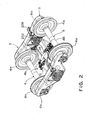
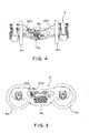
- FIGS. 1-5 there is shown a truck-mounted brake rigging, generally designated 10, for a railway car 2.
- the brake rigging 10 is installed within a conventional truck apparatus, generally designated as 3, carrying one end of the railway car body.
- truck apparatus 3 includes a pair of wheel sets 4 each having a pair of wheels 4a joined by an axle 4b and a frame 5 supported by the pair of wheel sets 4.
- the frame 5 includes a pair of side members 6a and 6b joined by a bolster 7.
- This brake rigging 10 comprises brake beams, generally designated 12 and 13, which are substantially identical, each such brake beam including a compression member 14, a tension member 16 and a strut member 18.
- the opposite ends of the compression member 14 and the tension member 16 may be permanently connected together in a conventional manner.
- Mounted on the respective ends of the brake beams 12 and 13 are brake heads 22.
- the compression member 14 and the tension member 16, of the respective brake beams 12 and 13, are spaced apart sufficiently to allow connection of the strut member 18 therebetween.
- a pair of force-transfer levers 24 and 26 are pivotally connected by pins 27 to the strut member 18 of the respective brake beams 12 and 13.
- One end of the force-transfer levers 24 and 26 is interconnected via the force-transmitting member 28, which may be in the form of an automatic slack adjuster device.
- the opposite end of the respective force-transfer levers 24 and 26 is connected to the pressure head of the brake actuator, generally designated 70, via a force-transmitting member or a return push rod assembly 32.
- the force-transfer levers 24 and 26, along with the slack adjuster assembly 28, the return push rod assembly 32, and the brake actuator 70 comprise a brake beam actuating linkage that interconnects the brake beams 12 and 13 via pivot pins 27 and thus the required brake actuation forces effectively act along these pins 27.
- the resultant of these forces is shown at X in FIG. 3 . Since the length of the slack adjuster assembly 28 increases with actuation of the brake actuator piston rod, it follows that brake beams 12 and 13 are moved apart by the brake beam linkage until the brake shoe engagement with the tread surface of the vehicle wheels 4a occurs.
- the push rod 30 moves in an opposed second direction causing the brake rigging 10 to release brakes.
- the pneumatic braking system as described above, can no longer be used.
- a hand brake mechanism which is mounted on each car, can be employed.
- the hand brake mechanism 40 has a housing, generally designated as 42, which comprises a back plate or wall 44, mountable on a railway car 2, and a cover 46 which is secured to the back wall 44.
- a chain 48 for application or release of the brakes, is connected, as is conventional, to the brake rigging 10 via a hand brake lever 50 and wound on a winding drum 52.
- the hand brake lever 50 is, in turn, connected to the brake actuator transfer lever or force transfer lever 24.
- a hand wheel 54 is rotated in a clockwise direction, as viewed in FIG. 1 , to wind the chain 48 about the winding drum 52 and to cause the hand brake lever 50 to be pulled in an outward direction away from the brake rigging 10.
- This causes the force transfer lever 24 to be rotated in a counterclockwise direction resulting in the push rod 30 being pulled in an outward direction and the required force being applied to the slack adjuster assembly 28.
- This force is similar to the force which is applied by the brake actuator push rod 30 of the brake actuator 70 when such is pressurized.
- the present invention overcomes the disadvantages related to improperly applied hand brake 40 or ruptured or disconnected hose (not shown) by providing a parking brake assembly.
- the parking brake assembly of the present invention has the added benefit in that it is automatically activated when the railway car 2 has been removed from the train consist and the pneumatic braking system used for activating the above discussed truck mounted brake rigging 10 has been disconnected. Once the railway car 2 has been reconnected with the train and the pneumatic braking system is again in effect, the spring applied parking brake assembly of the present invention is released.
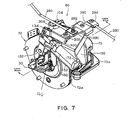
- the parking brake assembly generally designated as 60, includes the brake actuator 70, which has a housing 72 mounted on the first brake beam 12 adjacent the pivotal connection of the first transfer lever 24.
- the housing 72 has a first end 73 and an opposed second end 74.
- the first end 73 is provided with mounting member 73a for stationary securing the brake actuator 70 onto the beam 12.
- the first end 73 of the housing 72 is closed, while the second end 74 is generally open.
- a fluid-pressure-operable piston assembly 80 is mounted for a longitudinal reciprocal motion within the housing 72.
- the piston assembly 80 divides the housing 72 into a pressurized portion 75a disposed intermediate the first end 73 of the housing 72 and the first end 82 of the piston 80 and a non-pressurized portion 75b disposed adjacent the second end 74 thereof.
- a piston rod 90 is secured at a first end 92 thereof to a second end 84 of the piston assembly 80.
- the piston rod 90 is capable of extending through the axial opening 76 in the second end 74 of the housing 72 responsive to the supply of fluid pressure into the pressurized portion 75a.
- the piston rod 90 is secured at a second end 94 thereof to a first end of the push rod 30, whereby the piston rod 90 and the piston assembly 80 move with the push rod 30 in the first and second directions.
- the piston assembly 80 moves in the first direction toward the second end 74 of the housing 72 causing the piston rod 90 and the push rod 30 to move in such first direction for increasing the length of the first force-transmitting means, to accordingly increase the spaced-apart distance between the first and second brake beams 12 and 13 respectively in order to apply a braking force.
- a spring member 100 is disposed in the non-pressurized portion 75b of the housing 72 and is caged between an inner surface 77 of the second end 74 of the housing 72 and the second end 84 of the piston assembly 80.
- the spring member 100 is capable of exerting a force against the piston assembly 80 upon release of the spring member 100 responsive to evacuation of the fluid pressure from the pressurized portion 75a of the housing 72 causing longitudinal movement of the piston assembly 80 in the second direction within the housing 72 to accordingly retract the piston rod 90 thereinto. Accordingly, the push rod 30 will also move in the second direction and release the applied braking force.
- a fluid communication means 102 including a convention air pressure inlet 104, is also provided in fluid communication with the pressurized portion 75a of the housing 72 and with the brake pipe 8 for supplying the fluid pressure to the parking brake actuator 70 during brake application of the railway vehicle brake rigging 10 resulting in the longitudinal movement of the piston assembly 80 and the piston rod 90 in the first direction and in compression of the spring member 100.
- the fluid communication means 102 also is provided for evacuating the fluid pressure from the pressurized portion 75a of the housing 72 during brake release resulting in the longitudinal movement of the piston assembly 80 and the piston rod 90 in the second direction due to the force exerted by the released spring member 100.
- the parking brake assembly 60 further includes a clamping means, generally designated as 110, which is provided for maintaining the extended position of the push rod 30 during reduction of the fluid pressure in the brake pipe 8 to a predetermined level and for releasing the push rod 30 to move in the second direction due to the increase of the fluid pressure in the brake pipe 8 above such predetermined level.
- a clamping means generally designated as 110, which is provided for maintaining the extended position of the push rod 30 during reduction of the fluid pressure in the brake pipe 8 to a predetermined level and for releasing the push rod 30 to move in the second direction due to the increase of the fluid pressure in the brake pipe 8 above such predetermined level.
- such clamping means 110 includes a first elongated thread 112 formed on at least a portion of the exterior surface of the piston rod 90 movable through the non-pressurized portion 75b of the housing 72.
- a ratchet 114 is mounted within the non-pressurized portion 75b of the housing 72 for rotation about a longitudinal axis of the piston rod 90.
- a pair of optional bearings 115 may be provided for facilitating rotation of the ratchet 114.
- An aperture 116 is axially formed through the ratchet 114.
- a second thread 118 is formed on a surface of the axial aperture 116 for operable engagement with the first thread 112.
- a shaft 120 which is mounted for rotation in a spaced relationship with the ratchet 114. Rotational axis of the shaft 120 is substantially parallel to a rotational axis of the ratchet 114.
- the shaft 120 has a first end 122 thereof disposed within the non-pressurized portion 75b of the housing 72 and has a second end 124 thereof extending through an aperture 126 formed through the second end 74 of the housing 72 past an outer surface thereof.
- a holding pawl 128 is disposed within the non-pressurized portion 75b of the housing 72 and is secured to the shaft 120 for rotation therewith.
- the holding pawl 128 is rotateable in a first rotational direction for engagement with the ratchet teeth when a first rotational force is applied to the second end 124 of the shaft 120 due to the fluid pressure in the brake pipe 8 being reduced to a predetermined level. This engagement prevents movement of the push rod 30 in the second direction.
- the holding pawl 128 is rotateable in a second rotational direction for disengaging the ratchet teeth and permitting the push rod 30 to move in the second direction when a second rotational force is applied to at least one of the shaft 120 and the holding pawl 128 due to the increase of the fluid pressure in the brake pipe 8.
- the second end 74 of the housing 72 is formed by the first member 74a carrying the outer surface thereon and a second member 74b secured in spaced relationship with the first member 74a and wherein the ratchet 114 and the holding pawl 128 are mounted intermediate the first and the second members 74a and 74b.
- the first and the second members 74a and 74b are bolted to the flange 72a of the housing 72 in a conventional manner.
- FIGS. 6-8 has been illustrated by employing a brake actuator 70 having a housing 72 and a piston 80, it is also within the scope of the present invention to employ a brake actuator using an air spring.
- a brake actuator 70 having a housing 72 and a piston 80
- Such brake actuator is disclosed in a utility patent application Serial Number 10/645,035 filed on August 21, 2003 and entitled "Universal Brake Assembly. This utility patent application is assigned to the assignee of the present invention and its disclosure is incorporated into this document by reference thereto.
- the air spring is secured at one end thereof to a front plate-like member incorporating a push rod and is secured at a second end thereof to a mounting bracket for attachment to the brake beam.
- the piston rod 90 may be adapted with a flange 77 disposed on and secured to the first end 92 thereof, wherein a first plurality of apertures 98 will be formed therethrough for mounting to the threaded studs 78a of the air spring 78 with fasteners 79.
- the second end 74 of the housing 72 will be adapted, for example, with a horizontally disposed flange 74c and a vertically disposed flange 74d which is also spaced form the member 74a.
- a second plurality of apertures 98 will be formed through the flange 74d for mounting to the opposed side of the air spring 78 also having such threaded studs 78a.
- the flange 74d will be also adapted with the mounting member 73a of the housing 72 for mounting the brake actuator 60 to the brake beam 12.
- the flanges 74c and 74d will fix the second end 74 in a stationary position relative to the brake beam 13 and enable operation of the ratchet 114 and the holding pawl 128 according to the above described embodiments.
- the first and second members 74a and 74b will protect the ratchet 114 and the holding pawl 128 from detrimental elements, such as rocks, debris and the like, present during operation of the railway car 2.
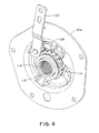
- the rotational force may be applied to the second end 124 of the shaft 120 manually, for example with a gripping type tool or a wrench (not shown), and preferably, an operating lever 130 is provided and has a first end 132 thereof disposed on and secured to the second end 124 of the shaft 120 for rotation therewith.
- the operating lever 130 is rotateable in the first rotational direction when the first rotational force is applied to a second end 134 thereof and is rotateable in the second rotational direction when the second rotational force is applied to the second end 134 thereof.
- an operating means generally designated as 140, which is responsive to a fluid pressure condition within the brake pipe 8 for selectively and automatically operating the clamping means 110 to maintain the push rod 30, after its movement in the first direction, in the position for applying brakes and to release the push rod 30 for movement in the second direction.
- such operating means 140 includes a mounting bracket 150 which is affixed to the outer surface of the second end 74 of the housing 72, preferably using the fasteners that attach the first and second members, 74a and 74b respectively, to the flange 72a.
- the mounting bracket 150 when installed, is disposed in a generally vertical plane.
- the mounting bracket 150 may be provided with a ledge portion 152, which is disposed generally horizontally.
- a pneumatically operated cylinder, generally designated as 160, is provided and is mounted on the ledge portion 152 of the mounting bracket 150.
- the pneumatically operated cylinder 160 has a casing 162, a piston assembly 164 mounted for a longitudinal movement within the casing, a piston rod 166 connected at a first end thereof to a first end of the piston assembly 164 and pivotally connected at a second end thereof to the second end 134 of the operating lever 130, and a spring 168 which is caged within the casing 162 between an end thereof and the second end of the piston assembly 164.
- piston assembly 164 and piston rod 166 move in a direction which is generally perpendicular to the movement direction of the piston assembly 80, piston rod 90 and push rod 30 as well as to the rotational axis of the ratchet 114 and the holding pawl 128.
- a fluid communication means 170 including a conventional fluid port 172, is provided in fluid communication with a second end of the piston assembly 164 and with the brake pipe 8 for supplying the fluid pressure to a second end of the piston assembly 164 causing the piston rod 166 to move outwardly and apply the second rotational force. Furthermore, the second fluid communication means is provided for evacuating the fluid pressure from the second end of the piston assembly 164 when the fluid pressure in the brake pipe 8 is reduced below the predetermined level causing the spring 168 to extend and retract the piston rod 166 into the casing 162, thus applying the first rotational force to the second end 134 of the lever 130.
- the fluid pressure is supplied to the pressurized portion 75a of the housing 72 causing the piston assembly 80 to move in the first direction toward the second end 74 of the housing 72 and against the resistance of the spring member 100 and, more particularly, causing the piston rod 90 and the push rod 30 to move in such first direction and apply brakes.
- the fluid pressure in the brake pipe 8 When a brake release is commanded and the fluid pressure in the brake pipe 8 begins to rise, the fluid pressure is evacuated from the pressurized portion 75a of the housing 72 though the directional valve 9 causing the spring member 100 to extend moving the push rod 30 in the second direction and releasing the brake force. As long as the fluid pressure in the brake pipe 8 is above the predetermined level, the piston rod 166 continues to apply the second rotational force to the operating lever 130 thus preventing the holding pawl 128 from engaging ratchet teeth.
- the fluid pressure in the brake pipe 8 reduces below the predetermined level, which is generally set below the level present in full service brake application, the fluid pressure is evacuated from the pneumatically operated cylinder 160, causing the spring 168 to extend and retract the piston rod 166 into the casing 162, thus applying the first rotational force to the second end 134 of the lever 130 and engaging the holding pawl 128 with the ratchet 114. Since the brake actuator 70 will operate as described above to move the push rod 30 in the first direction apply braking force, the engagement of the holding pawl 128 with the ratchet 114 will maintain the push rod 30 in such brake applied condition.
- the ratchet teeth are formed so that the ratchet 114 rotates to allow movement of the push rod 30 in the first direction even when the holding pawl 128 engages the ratchet 114 prior to the push rod 30 completing its movement to apply brakes.
- the present invention is not concerned with timing issues between operation of the brake actuator 70 and operation of the pneumatically operated cylinder 160.
- the predetermined fluid pressure level in the brake pipe 8 at which the holding pawl 128 engages the ratchet 114 is also dependent on the rate of the spring 168 as well as on specific application requirements. For example, it may be desirable for the holding pawl 128 to engage the ratchet 114 only during a rapid fluid pressure decrease that is commonly known as an emergency brake application when the fluid pressure in the brake pipe reduces to about ten PSI and then further to zero PSI.
- a manually operable release means generally designated as 200, which is coupled to the pneumatically operated cylinder 160 for manually releasing the push rod 30 to move in the second direction.
- such manually operable release means 200 includes a release shaft 202 treadably secured to the casing 162 of the pneumatically operated cylinder 160.
- the release shaft 202 has a first end thereof coaxially secured to the second end of the piston 164 and having a second end thereof extending outwardly from the casing 162, whereby selective manual rotation of the second end of the release shaft 202 causes extension or retraction of the piston rod 166 rotating the operating lever 130 in the first or second rotational directions.
- the manually operable release means 200 includes a valve 210, best illustrated in FIG. 12 , which is disposed within the fluid communication means 170 intermediate the brake pipe 8 and the pneumatically operated cylinder 160.
- the valve 210 is operable in a first position for supplying the fluid pressure to the pneumatically operated cylinder 160 when the fluid pressure in the brake pipe 8 is maintained above the predetermined level. In this position, the fluid pressure compresses an extension spring 212 mounted within the valve 210 allowing the fluid pressure to flow through to the pneumatically operated cylinder 160.
- the valve 210 is also operable in a second position to discontinue, due to release of the compressed spring 212, supply of the fluid pressure to the pneumatically operated cylinder 160 and exhaust the fluid pressure from the pneumatically operated cylinder 160 to atmosphere.
- the spring 212 extends and blocks the flow of the fluid pressure through the valve 210 and opens passage to its exhaust port.
- the valve 210 also includes a manually operable means, such as a pushbutton 214 disposed therein, for manually restoring the supply of the fluid pressure to the pneumatically operated cylinder 160.
- Manual actuation of the pushbutton 214 briefly compresses the spring 212 to allow the flow of the fluid pressure through the valve 210 which will keep the spring 212 in a compressed condition when the pushbutton 214 is released.
- a pair of valves 210 may be provided, each installed adjacent a respective end of the railway car 2 to reduce the labor of releasing applied parking brake assembly 60 by eliminating the operator of the railway car 2 to walk to the end having the parking brake assembly 60 installed on.
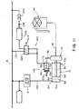
- the manually operable release means 200 may include a two-position, three-port valve 220, best shown in FIG. 11 .
- An auxiliary reservoir 222 of the fluid pressure may be connected at one port thereof to the brake pipe 8 through a check valve 224 and a restricting choke 226 mounted in series with the check valve 224 and connected at another port thereof to the valve 220.
- valve 210 or 220 it is also within the scope of the present invention to provide other means for operating the valve 210 or 220 to restore of the fluid pressure to the pneumatically operated cylinder 160.
- a three-way valve 230 may be provided, wherein the pushbutton 214 has been replaced with a solenoid 232 so that the valve 210 can be operable in the second position for allowing flow of the fluid pressure therethrough by an electrical signal which can be remotely transmitted, for example from the locomotive (not shown) by any well known means including wires, radio frequency, satellite communicating and the like methods.
- the valve 230 may be adapted with a second solenoid 234 to remotely operate such valve 230 into the position for enabling flow of the fluid pressure to the cylinder 160 and, more particularly, allowing remote application of the parking brake assembly 60.
- valve 210, 220 or 230 in combination with the release shaft 202 of FIG. 11 .
- a manually operable valve 210 or 220 is mounted in close proximity to the end or the side of the railway car 2 enabling the operator of the railway car 2 to safely and conveniently operate the parking brake assembly 60 from one side of the railway car 2 without the need to reach underneath thereof and into the confines of the truck apparatus 3.
- manual release means 200 are of a pneumatic type. It is also possible to provide the manual release means of a solely mechanical type which does not depend on presence or absence of the fluid pressure in the brake pipe 8 to release applied brakes.
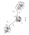
- Such mechanical manual release means, generally designated as 250, will be described below in combination with the brake rigging 10 installed within the truck apparatus 3 carrying one end of the railway vehicle body. As was described above, such truck apparatus 3 includes the frame 5 having the pair of side members 6a and 6b joined by the bolster 7.
- the manual release means 250 includes a first plate-like member 252 abuttingly engaging an inner vertical surface portion of one side member, shown as 6a, of the truck apparatus 3.
- a first plurality of apertures 254 are formed through the first plate-like member 252 and are disposed in a predetermined pattern.
- a second plate-like member 256 abuttingly engages an outer vertical surface portion of the side member 6a.
- a second plurality of apertures 254 are formed through the second plate-like member 256 and are disposed in the same predetermined pattern as the apertures 254 formed through the first plate-like member 252.
- Each of the second plurality of apertures 254 is aligned with a respective one of the first plurality of apertures 254.
- each rod 260 there is a plurality of rods 260 provided with each passed through aligned apertures 254 in the first and second plate-like members, 252 and 256 respectively.
- a male thread 262 is formed on each end of each rod 260.
- a plurality of threaded fasteners 264 is used with each fastener 264 operably engaging a respective rod end for affixing the first and second plate-like members, 252 and 256 respectively, about the side member 6a by caging a portion thereof between these plate-like members.
- an elongated slot 270 is formed though a first plate-like member 252 and extends in a generally horizontal direction.
- An L-shaped slot 272 is formed in the second plate-like member 256 and has a horizontal leg 274 thereof aligned with the elongated slot 270 formed through the first plate-like member 252.
- the L-shaped slot 272 also has a vertical leg 276.
- An elongated link member 280 is provided and has a predetermined shape for routing through the truck apparatus 3.
- the first end 282 of the link member 280 is passed through the elongated slot 270 and through the L-shaped slot 272 and extends outwardly from the second plate-like member 254.
- a grip member 286 is disposed on and secured to the first end 282 of the elongated link member 280. This grip member 286 is manually operable to move the link member 280 from a first position enabling application of the parking brake assembly 60 into a second position enabling release of an applied parking brake assembly 60.
- the grip member 286 may be shaped as a conventional handle and may be further provided integral with the link member 280 by bending the second end 284 thereof.
- a bias means is provided and is engageable with the elongated link member 280 for returning it into the first position upon release of the grip member 286.
- the presently preferred means for connecting the second end 284 of the elongated link member 280 to the parking brake assembly 60 includes first release lever 290 which is pivotally connected to the mounting bracket 150.
- first release lever 290 which is pivotally connected to the mounting bracket 150.
- pivotal connection may be achieved with a pin or fastener 292 passed through aligned apertures (not shown) in the first release lever 290 and the mounting bracket 150.
- pivotally connecting the second end 284 of the elongated link 280 to one end of the first release lever 290.
- such second end 284 may be formed as a bifurcated portion with an aperture (not shown) formed therethrough and aligned with another aperture (not shown) formed through the first release lever 290 and wherein a pin or fastener 294 is passed through these aligned apertures (not shown).
- a second release lever 300 having a first end 302 thereof pivotally connected to a second end of the first release lever 290 and having a second end 304 thereof pivotally connected to the second end 134 of the operating lever 130.
- manually initiated movement of the elongated link 280 from the first position toward the second position causes rotational movement of the operating lever 130 in the second rotational direction due to rotation of each of the first and second release levers, 290 and 300 respectively, thus enabling the holding pawl 284 to disengage the ratchet teeth and enable the push rod 30 to move in the second direction due to extension of the spring 100 thus releasing the applied braking force.
- the grip member 286 is movable through a vertical leg 276 of the L-shaped slot 272 and, accordingly,'the manual release mechanism 250 includes a pair of spacers 258 rigidly secured to an inner surface of the second plate-like member 256 for positioning it in a spaced relationship with the outer surface of the side member 6a and for enabling movement of the grip member 286 through the vertical leg 276 of the L-shaped slot 272.
- the employment of the horizontally disposed leg 274 enables the operator of the railway car 2 to move the grip member 286 through the vertical leg 276 sufficiently to clear the outer surface of the second plate-like member 256 and then move the grip member 286 laterally along the first leg 274 to latch such grip member 286 against the outer surface of the second plate-like member 256 to prevent the elongated link 280 from returning into the first position and, more particularly, prevent the holding pawl 128 from reengaging the ratchet 114.
- the railway car 2 can be freely moved.
- the user laterally moves the grip member 286 in the opposite direction so it can move through the vertical leg 276 thus allowing the link member 280 to return into the first position due to the action of the bias means. It is also possible to angle the leg 274 downwardly in order to facilitate retention of the grip member 286.
- the bias means may be simply formed by a first washer 310 movably secured to the elongated link member 280, a second washer 312 rigidly secured to the elongated link member 280 in spaced relationship with the first washer 310, and a spring 314 caged between the first washer 310 and the second washer 312.
- the manual release means 250 enables the operator of the railway car 2 to safely and conveniently release the applied parking brake assembly 60 from one side of the railway car 2 without the need to reach underneath thereof and into the confines of the truck apparatus 3.
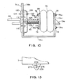
- manual release means 250 has been shown and described in terms of the parking brake assembly 60 being used with a truck mounted brake system, it will be apparent to those skilled in the art that the manual release means 250 may be applied with the parking brake assembly being used with a car body mounted brake system by simply securing the second plate-like member 256 to the side of the railway car body and simply connecting the first end 282 of the elongated member 280 to the second plate-like member 256, as depicted in FIG. 13 .
- the present invention also contemplates to provide means for compensating for bail of the push rod 30 moving laterally during the rotation of the force-transfer lever 24 and, at the same time, prevent rotation of the piston rod 90 during longitudinal movement.
- such means includes an axial cavity 322 formed within the piston rod 90 and defining a peripheral wall of the piston rod 90.
- An aperture is formed through the peripheral wall.
- An elongated abutment 326 is disposed on and secured to the push rod 30 and is positioned within the axial cavity 322.
- a slot 328 is formed through the abutment 326 in alignment with the aperture 330 formed through the peripheral wall of the piston rod 90.
- An elongated pin 332 is frictionally passed through a combination of the slot 328 and the aperture 330 formed through the peripheral wall of the piston rod 90 allowing for axial movement of the push rod 30 while preventing rotational movement of the piston rod 90.
- the present invention may provide an ergonomic alternative to the currently used hand wheel activated hand brakes of the prior art, although as it has been shown in various figures, it complements such hand brakes. Additionally, because the parking brake assembly 60 of the present invention automatically activates upon removal of the car from the pneumatic braking system of the railway vehicle, the possibility of unwanted movement of a parked railway car 2 has been at least substantially reduced.
- the present invention also provides a novel alternative to a commonly used brake actuators of a spring-applied, air-released type wherein the braking force to the wheels 4a is applied due to loss of the fluid pressure in the brake pipe 8.
- the present invention applies the braking force (or applies brakes) in a conventional manner when the fluid pressure in the brake pipe 8 is partially reduced and maintains the applied braking force and, consequently, the applied brakes when the fluid pressure in the brake pipe reduces to zero PSI.
- Such car mounted brake system may be of a type as disclosed for example in FIG. 1 of U.S. Pat. No. 6,854,570 issued to Connel and whose teachings are incorporated into this document by reference thereto. Accordingly, the brake actuator 12 of FIG. 1 of U.S. Pat. No. 6,854,570 will be replaced with a brake actuator constructed according to the construction of the brake actuator 70 with further accommodations for operating a pair of truck mounted brake riggings from a single brake actuator.
- At least the cylinder 160 may be replaced with a linear electrical drive, such as a linear motor, solenoid or a screw drive, which can be locally or remotely operated to at least release the applied parking brake assembly which can be also of an electrically actuated type.
- a linear electrical drive such as a linear motor, solenoid or a screw drive
Landscapes
- Engineering & Computer Science (AREA)
- Transportation (AREA)
- Mechanical Engineering (AREA)
- Braking Arrangements (AREA)
- Braking Systems And Boosters (AREA)
Claims (18)
- Parkbremsenaktuator (70) für ein Bremssystem (10) für ein Schienenfahrzeug, das in fluidtechnischer Verbindung mit einem Bremsenrohr (8), das Fluiddruck trägt, des Schienenfahrzeugs steht, wobei das Bremssystem (10) mindestens eine Schubstange (30) aufweist, die zum Bewegen darin montiert ist, wobei die Schubstange (30) auf eine Verringerung des Fluiddrucks in dem Bremsenrohr (8) reagiert, um sich in eine erste Richtung zu bewegen, die das Bremssystem (10) veranlasst, die Bremsen anzulegen, und die auf eine Steigerung des Fluiddrucks in dem Bremsrohr (8) reagiert, um sich in eine entgegengesetzte zweite Richtung zu bewegen, die das Bremssystem (10) veranlasst, die Bremsen zu lösen, wobei der Parkbremsenaktuator (70) Folgendes aufweist:(a) ein hohles Gehäuse (72), das in einen vorbestimmten Abschnitt des Bremssystems (10) eingerückt werden kann, wobei das Gehäuse ein erstes Ende (73) und ein entgegengesetztes zweites Ende (74) aufweist, wobei das erste Ende Mittel zum Montieren des Parkbremsenaktuators (70) an einem Abschnitt des Bremssystems (10) aufweist, wobei das zweite Ende eine Öffnung (76) aufweist, die dadurch axial ausgebildet ist;(b) eine Kolbenanordnung (80), die für eine Längsbewegung innerhalb des Gehäuses (72) montiert ist und das Gehäuse in einen mit Druck beaufschlagten Abschnitt (75a), der zwischen dem ersten Ende (73) des Gehäuses und einem ersten Ende (82) der Kolbenanordnung (80) angeordnet ist, und einen nicht mit Druck beaufschlagten Abschnitt (75 b), der neben dem zweiten Ende (74) des Gehäuses angeordnet ist, teilt;(c) eine Kolbenstange (90), die an ihrem ersten Ende (92) an einem zweiten Ende (84) der Kolbenanordnung (80) befestigt und fähig ist, sich durch die axiale Öffnung (76) in dem zweiten Ende (74) des Gehäuses (72) als Reaktion auf das Zuführen von Fluiddruck zu erstrecken, wobei die Kolbenstange (90) an ihrem zweiten Ende (94) an einem ersten Ende der Schubstange (30) befestigbar ist, wobei sich die Kolbenstange (90) und die Kolbenanordnung (80) längs mit der Schubstange (30) in die erste und die zweite Richtung bewegen;(d) Mittel zum Verhindern der Drehung der Kolbenstange (90) während ihrer Längsbewegung innerhalb des Gehäuses;(e) ein Federelement (100), das in dem nicht mit Druck beaufschlagten Abschnitt (75b) des Gehäuses (72) angeordnet und zwischen einer inneren Oberfläche (77) des zweiten Endes (74) des Gehäuses (72) und dem zweiten Ende (84) der Kolbenanordnung (80) käfigartig eingeschlossen ist, wobei das Federelement (100) fähig ist, eine Kraft gegen die Kolbenanordnung (80) bei der Freigabe des Federelements als Reaktion auf einen Verlust des Fluiddrucks in dem mit Druck beaufschlagten Abschnitt (75a) des Gehäuses (72) auszuüben und die Längsbewegung der Kolbenanordnung (80) innerhalb des Gehäuses (72) in die zweite Richtung zu veranlassen, um die Kolbenstange (90) darin entsprechend zurückzuziehen;(f) ein Fluidverbindungsmittel (102) in fluidtechnischer Verbindung mit dem mit Druck beaufschlagten Abschnitt (75a) des Gehäuses (72) und mit dem Bremsrohr (8) zum Zuführen des Fluiddrucks zu dem Parkbremsenaktuator (70) während der Bremsenanlegung des Bremssystems (10) des Schienenfahrzeugs, das in der Längsbewegung der Kolbenanordnung (80) und Bewegung der Kolbenstange (90) in die erste Richtung und im Komprimieren des Federelements (100) resultiert, wobei das Fluidverbindungsmittel (102) zum Ableiten des Fluiddrucks von dem mit Druck beaufschlagten Abschnitt (75a) des Gehäuses (72) während des Lösens der Bremse in der Längsbewegung der Kolbenanordnung (80) und der Kolbenstange (90) in die zweite Richtung aufgrund der Kraft resultiert, die von dem freigegebenen Federelement (100) ausgeübt wird;(g) ein erstes längliches Gewinde (112), das auf mindestens einem Abschnitt der Kolbenstange (90) ausgebildet ist, der durch den nicht mit Druck beaufschlagten Abschnitt (75b) des Gehäuses (72) bewegt werden kann,(h) ein Klinkenrad (114), das innerhalb des nicht mit Druck beaufschlagten Abschnitts (75b) des Gehäuses (72) zur Drehung um eine Längsachse der Kolbenstange (90) montiert ist;(i) eine Öffnung (116), die axial durch das Klinkenrad (114) ausgebildet ist;(j) ein zweites Gewinde (118), das auf einer Oberfläche der axialen Öffnung (115) für den betrieblichen Eingriff in das erste Gewinde (112) ausgebildet ist;(k) eine Welle (120), die zur Drehung in einer beabstandeten Beziehung zu dem Klinkenrad (114) montiert ist, wobei eine Rotationsachse der Welle (120) im Wesentlichen zu einer Rotationsachse des Klinkenrads (114) parallel ist, wobei die Welle (120) ihr erstes Ende (122) innerhalb des nicht mit Druck beaufschlagten Abschnitts (75b) des Gehäuses (72) angeordnet hat, und wobei sich ihr zweites Ende (124) durch eine Öffnung (126), die durch das zweite Ende (74) des Gehäuses (72) ausgebildet ist, an einer äußeren Oberfläche davon vorbei erstreckt; und(l) eine Halteklinke (128), die innerhalb des nicht mit Druck beaufschlagten Abschnitts (75b) des Gehäuses (72) angeordnet und an der Welle (120) zum Drehen damit befestigt ist, wobei die Halteklinke (128) in eine erste Rotationsrichtung zum Eingreifen mit den Klinkenradzähnen gedreht werden kann, wenn eine erste Rotationskraft an das zweite Ende (124) der Welle (120) aufgrund des Verringerns des Fluiddrucks auf ein vorbestimmtes Niveau in dem Bremsrohr (8) angelegt wird, wobei der Eingriff die Bewegung der Schubstange (30) in die zweite Richtung verhindert, wobei die Halteklinke (128) in eine zweite Richtung drehbar ist, um den Klinkenradzahn auszurücken und es der Schubstange (30) zu erlauben, sich in die zweite Richtung zu bewegen, wenn eine zweite Rotationskraft an das zweite Ende der Welle (120) und/oder die Halteklinke (128) aufgrund der Steigerung des Fluiddrucks in dem Bremsrohr (8) angelegt wird.
- Parkbremsenaktuator (70) nach Anspruch 1, wobei der Parkbremsenaktuator (70) einen Betätigungshebel (130) aufweist, dessen erstes Ende (132) auf dem zweiten Ende (124) der Welle (120) zum Drehen mit dieser angeordnet und befestigt ist, wobei der Betätigungshebel (130) in die erste Rotationsrichtung drehbar ist, wenn die erste Rotationskraft an sein zweites Ende (134) angelegt wird, und in die zweite Rotationsrichtung drehbar ist, wenn die zweite Rotationskraft an sein zweites Ende (134) angelegt wird.
- Parkbremsenaktuator (70) nach Anspruch 1, wobei das zweite Ende (74) des Gehäuses (72) durch ein erstes Element (74a), das die erste Oberfläche darauf trägt, und ein zweites Element (74b), das die innere Oberfläche des zweiten Endes (74) des Gehäuses (72) trägt, ausgebildet ist, wobei das zweite Element (74b) in beabstandeter Beziehung zu dem ersten Element (74a) befestigt ist und wobei das Klinkenrad (114) und die Halteklinke (128) zwischen dem ersten (74a) und dem zweiten Element (74b) montiert sind.
- Parkbremsenaktuator (70) nach Anspruch 1, wobei der Parkbremsenaktuator (70) Folgendes aufweist:(a) einen Montageträger (150), der an der äußeren Oberfläche des zweiten Endes (74) des Gehäuses (72) befestigt ist;(b) einen pneumatisch betätigten Zylinder (160), der auf den Träger (150) montiert ist und eine Ummantelung (162) aufweist, eine zweite Kolbenanordnung (164) die für eine Längsbewegung innerhalb der Ummantelung montiert ist, eine zweite Kolbenstange (166), die an ihrem ersten Ende mit einem ersten Ende der zweiten Kolbenanordnung (164) verbunden ist und an ihrem zweiten Ende mit dem zweiten Ende (134) des Betätigungshebels (130) verbunden ist, und eine zweite Feder (168), die in der Ummantelung (162) zwischen einem Ende davon und dem ersten Ende der zweiten Kolbenanordnung (164) käfigartig eingeschlossen ist; und(c) ein zweites Fluidverbindungsmittel (170) in fluidtechnischer Verbindung mit einem zweiten Ende der zweiten Kolbenanordnung (164) und mit dem Bremsrohr (8), um den Fluiddruck zu einem zweiten Ende der zweiten Kolbenanordnung (164) zu liefern, was die zweite Kolbenstange (166) veranlasst, sich auswärts zu bewegen und die zweite Rotationskraft anzulegen, wobei das zweite Fluidverbindungsmittel (170) ferner den Fluiddruck von dem zweiten Ende der zweiten Kolbenanordnung (164) ableitet, wenn der Fluiddruck in dem Bremsrohr (8) unter das vorbestimmte Niveau verringert wird, was die zweite Feder (168) veranlasst, die zweite Kolbenstange (166) in die Ummantelung (162) zurückzuziehen und die erste Rotationskraft an das zweite Ende (134) des Hebels (130) anzulegen.
- Parkbremsenaktuator (70) nach Anspruch 4, wobei der Parkbremsenaktuator (70) ferner ein manuell betätigbares Lösemittel (200) aufweist, das mit dem pneumatischen betätigten Zylinder (160) zum manuellen Freigeben der Schubstange (30), um sich in die zweite Richtung zu bewegen, gekuppelt ist.
- Parkbremsenaktuator (70) nach Anspruch 5, wobei das manuelle Lösemittel (200) eine Lösewelle (202) aufweist, die durch ein Gewinde an der Ummantelung (162) des pneumatisch betätigten Zylinders (160) befestigt ist, wobei die Lösewelle (202) ihr erstes Ende koaxial an einem zweiten Ende der zweiten Kolbenanordnung (164) befestigt hat, und sich ihr zweites Ende auswärts von der Ummantelung (162) erstreckt, wobei selektive manuelle Drehung des zweiten Endes der Lösewelle (202) selektives Ausfahren und Zurückziehen der zweiten Kolbenstange (166), die jeweils den Betätigungshebel (130) in die zweite und die erste Rotationsrichtung dreht, veranlasst.
- Parkbremsenaktuator (70) nach Anspruch 5, wobei das manuelle Lösemittel (200) ein Ventil (210) aufweist, das innerhalb des zweiten Fluidverbindungsmittels (170) angeordnet ist, wobei das Ventil (210) in einer ersten Position betätigbar ist, um Fluiddruck zu dem pneumatisch betätigten Zylinder (160) zuzuführen, wenn der Fluiddruck in dem Bremsrohr (8) oberhalb des vorbestimmten Niveaus gehalten wird, und in eine zweite Position betätigbar ist, um die Zuführung des Fluiddrucks zu dem pneumatischen betätigten Zylinder (160) zu unterbrechen, wenn der Fluiddruck in dem Bremsrohr unter das vorbestimmte Niveau fällt.
- Parkbremsenaktuator (70) nach Anspruch 7, wobei das Ventil (210) Mittel aufweist, die betrieblich damit zum Wiederherstellen der zuvor unterbrochenen Zuführung des Fluiddrucks zu dem pneumatisch betätigten Zylinder (168) verbunden sind.
- Parkbremsenaktuator (70) nach Anspruch 8, wobei das Mittel zur Wiederherstellung der Zuführung von Fluiddruck einen manuell betätigbaren Druckknopf (214) aufweist.
- Parkbremsenaktuator (70) nach Anspruch 8, wobei das Mittel zur Wiederherstellung der Zuführung von Fluiddruck eine elektrisch betriebene Zylinderspule (230) aufweist, die betrieblich mit einer Quelle eines elektrischen Signals verbunden ist.
- Parkbremsenaktuator (70) nach Anspruch 1, wobei das Mittel zum Verhindern der Rotation der Kolbenstange Folgendes aufweist(a) einen axialen Hohlraum (322), der innerhalb der Kolbenstange (90) ausgebildet ist und eine Umfangswand der Kolbenstange (90) definiert;(b) eine Öffnung, die durch die Umfangswand ausgebildet ist;(c) einen Anschlag (326), der auf der Schubstange (90) angeordnet und an ihr befestigt ist, wobei der Anschlag innerhalb des axialen Hohlraums (322) der Kolbenstange positioniert ist;(d) einen Schlitz (328), der durch den Anschlag (326) gefluchtet mit der Öffnung (330), die durch die Umfangswand der Kolbenstange (90) ausgebildet ist; und(e) einen länglichen Stift (332), der reibend durch eine Kombination der Öffnung (330), die durch die Umfangswand der Kolbenstange (90) und den Schlitz ausgebildet ist, durchgeht.
- Parkbremsenanordnung (60) für ein Bremssystem (10) in einem Schienenfahrzeug, wobei das Bremssystem mindestens eine Schubstange (30) aufweist, die zur Wechselbewegung innerhalb des Bremssystems montiert ist, und einen Bremsaktuator, der durch pneumatischen Fluiddruck betätigbar ist, der durch eine Schubstange (30) verbunden ist und auf die Zuführung pneumatischen Fluiddrucks reagiert, um die Schubstange (30) längs in eine erste Richtung zu bewegen, um eine Bremskraft anzulegen, wobei der Bremsaktuator auf einen Verlust der Zuführung des pneumatischen Fluiddrucks reagiert, um die Schubstange (30) in eine zweite Richtung zu bewegen, um die Bremskraft zu lösen, wobei die Parkbremsenanordnung Folgendes aufweist:(a) ein erstes längliches Gewinde (112), das konzentrisch mit einer Längsachse der Schubstange (30) ausgebildet ist;(b) ein Klinkenrad (114), das zur Drehung um die Längsachse der Schubstange (30) montiert ist;(c) eine Öffnung (116), die axial durch das Klinkenrad ausgebildet ist;(d) ein zweites Gewinde (118), das auf einer Oberfläche der axialen Öffnung (115) für den betrieblichen Eingriff mit dem ersten Gewinde ausgebildet ist;(e) eine Welle (120), die zur Drehung in einer beabstandeten Beziehung mit dem Klinkenrad (114) montiert ist, wobei eine Rotationsachse der Welle (120) im Wesentlichen zu einer Rotationsachse des Klinkenrads (114) parallel ist;(f) eine Halteklinke (128), die auf der Welle angeordnet und zum Drehen mit ihr befestigt ist, wobei die Halteklinke (128) in eine erste Rotationsrichtung zum Eingreifen mit dem Klinkenradzahn drehbar ist, wenn eine erste Rotationskraft an die Welle (120) aufgrund des Verringerns des Fluiddrucks in dem Bremsrohr (8) auf ein vorbestimmtes Niveau angelegt wird, wobei der Eingriff Bewegung der Schubstange (30) in die zweite Richtung verhindert, wobei die Halteklinke (128) in eine zweite Rotationsrichtung drehbar ist, um den Klinkenradzahn auszurücken und es der Schubstange (30) zu erlaubt, sich in die zweite Richtung zu bewegen, wenn eine zweite Rotationskraft an die Welle (120) und/oder die Halteklinke (128) aufgrund der Steigerung des Fluiddrucks in dem Bremsrohr angelegt wird;(g) einen Betätigungshebel (130), dessen erstes Ende (132) auf einem Ende der Welle (120) angeordnet und zur Drehung mit ihr in die erste und die zweite Rotationsrichtung befestigt ist, und dessen zweites Ende (134) jeweils die erste und zweite Rotationkraft aufnimmt;(h) einen Montageträger (150), der an dem pneumatisch mit Fluiddruck betätigbaren Bremsaktuator und/oder dem zweiten beabstandeten Träger und/oder dem zweiten beabstandeten Träger befestigt ist;(i) einen pneumatisch betätigten Zylinder (160), der auf den Träger (150) montiert ist und eine Ummantelung (162) aufweist, eine Kolbenanordnung (164), die für eine Längsbewegung innerhalb der Ummantelung montiert ist, eine Kolbenstange (166), die mit ihrem ersten Ende mit dem ersten Ende der Kolbenanordnung (164) verbunden ist und an ihrem zweiten Ende mit dem zweiten Ende (134) des Betätigungshebel (130) verbunden ist, und eine Feder (168), die innerhalb der Ummantelung (162) zwischen einem Ende davon und dem ersten Ende der Kolbenanordnung (164) käfigartig eingeschlossen ist; und(j) ein Fluidverbindungsmittel (170) in fluidtechnischer Verbindung mit einem zweiten Ende der Kolbenanordnung (164) und mit dem Bremsrohr (8) zum Zuführen des Fluiddrucks zu dem zweiten Ende der Kolbenanordnung (164), was die Kolbenstange (166) veranlasst, sich auswärts zu bewegen und die zweite Rotationskraft an das zweite Ende (134) des Betätigungshebels (130) anzulegen und um den Fluiddruck von dem zweiten Ende der Kolbenanordnung (164) abzuleiten, wenn der Fluiddruck in dem Bremsrohr (8) unter das erste vorbestimmte Niveau verringert wird, was die Feder (168) veranlasst, die Kolbenstange (166) in die Ummantelung (162) zurückzuziehen und die erste Rotationskraft an das zweite Ende (134) des Betätigungshebels (130) anzulegen.
- Parkbremsenanordnung (60) nach Anspruch 12, wobei das Bremssystem (10) innerhalb eines Drehgestells (3), das ein Ende eines Schienenfahrzeugkarosserie trägt, installiert ist, wobei ein solches Drehgestell (3) ein Paar von Radsätzen (4) aufweist, die jeweils ein Paar Räder (4a) aufweisen, die durch eine Achse (4b) verbunden sind, und einen Rahmen (5), der von dem Paar von Radsätzen (4) getragen wird, und wobei die Parkbremsenanordnung (60) ein Lösemittel (250) aufweist, das manuell außen zu einem Seitenelement des Drehgestells (3) betätigt werden kann, um eine angelegte Parkbremsenanordnung (60) zu lösen.
- Parkbremsenanordnung (60) nach Anspruch 13, wobei das manuelle Lösemittel (250) Folgendes aufweist:(a) ein erstes plattenähnliches Element (252), das anschlagend in einen inneren vertikalen Oberflächenabschnitt des Seitenelements (6a) des Drehgestells eingreift;(b) eine erste Mehrzahl von Öffnungen (254), die durch das erste plattenähnliche Element (252) ausgebildet und in einem vorbestimmten Muster angeordnet sind;(c) ein zweites plattenähnliches Element (256), das anschlagend in einen äußeren vertikalen Oberflächenabschnitt des Seitenelements (6a) eingreift;(d) eine zweite Mehrzahl von Öffnungen (254), die durch das zweite plattenähnliche Element (256) ausgebildet und in dem vorbestimmten Muster angeordnet ist, wobei jede der zweiten Mehrzahl von Öffnungen (254) mit einer jeweiligen Öffnung der ersten Mehrzahl von Öffnungen (254) ausgerichtet ist;(e) eine Mehrzahl von Stangen (260), die jeweils durch jeweils ausgerichtete Öffnungen (254) in dem ersten und dem zweiten plattenähnlichen Element (252, 256) durchgehen;(f) ein Außengewinde (262), das an jedem Ende der Stange (260) ausgebildet ist;(g) eine Vielzahl von Gewindebefestigungen (264), die jeweils betrieblich in ein jeweiliges Stangenende zum Befestigen des ersten und des zweiten plattenähnlichen Elements (252, 256) an dem Seitenelement eingreifen;(h) einen länglichen Schlitz (270), der durch ein erstes plattenähnliches Element (252) ausgebildet ist und sich in eine allgemein horizontale Richtung erstreckt;(i) einen L-förmigen Schlitz (272), der in dem zweiten plattenähnlichen Element (256) ausgebildet ist und einen horizontalen Schenkel (274) mit dem länglichen Schlitz (270), der durch das erste plattenähnliche Element (252) ausgebildet ist, ausgerichtet hat;(j) ein längliches Verbindungselement (280), das durch das Drehgestell (3) verlegt ist, wobei ein erstes Ende (282) des Verbindungselements durch den länglichen Schlitz (270) und einen zweiten L-förmigen Schlitz (272) durchgeht und sich von dem zweiten plattenähnlichen Element (254) auswärts erstreckt;(k) Mittel zum Verbinden eines zweiten Endes (284) des Verbindungselements (280) mit der Parkbremsenanordnung (60);(l) ein Greifelement (286), das auf dem ersten Ende (282) des länglichen Verbindungselements (280) angeordnet und an diesem befestigt ist, wobei das Greifelement (286) manuell betätigt werden kann, um das Verbindungselement (280) von einer ersten Position, die das Anlegen der Parkbremsenanordnung (60) erlaubt, in eine zweite Position, die das Lösen der angelegten Parkbremsenanordnung (60) erlaubt, zu bewegen; und(m) ein Vorspannmittel, das in das längliche Verbindungselement (280) eingreifen kann, um es nach dem Freigeben des Greifelements in die erste Position zurückzustellen.
- Parkbremsenanordnung (60) nach Anspruch 14, wobei das Mittel zum Verbinden des zweiten Endes (284) des länglichen Verbindungselements (280) mit der Parkbremsenanordnung (60) Folgendes aufweist:(a) einen ersten Lösehebel (290), der schwenkend mit dem zweiten Montageträger (150) verbunden ist;(b) Mittel zum schwenkenden Verbinden des zweiten Endes (284) der länglichen Verbindung (280) mit einem Ende des ersten Lösehebels (290);(c) einen zweiten Lösehebel (300), dessen erstes Ende (302) schwenkend mit einem zweiten Ende des ersten Lösehebels (290) verbunden ist, und dessen zweites Ende (304) schwenkend mit dem zweiten Ende (134) des Betätigungshebels (130) verbunden ist, wobei die manuell betätigbare Bewegung der länglichen Verbindung (280) von der ersten Position die Drehbewegung des Betätigungshebels (130) in die zweite Rotationsrichtung aufgrund der Drehung sowohl des ersten als auch des zweiten Lösehebels (290, 300) veranlasst, wodurch es der Halteklinke (284) ermöglicht wird, den Klinkenradzahn auszurücken und es der Schubstange (30) ermöglicht, die Bremskraft zu lösen.
- Parkbremsenanordnung (60) nach Anspruch 14, wobei die Parkbremsenanordnung ferner ein zweites manuelles Lösemittel (250) aufweist, das manuell extern zu einem entgegengesetzten Seitenelement des Drehgestells (3) zum Lösen einer angelegten Parkbremsenanordnung betätigbar ist.
- Parkbremsenanordnung (60) nach Anspruch 14, wobei das Vorspannmittel eine erste Unterlegscheibe (310) aufweist, die auf dem länglichen Verbindungselement (280) in beabstandeter Beziehung zu dessen zweitem Ende angeordnet ist, eine zweite Unterlegscheibe (312), die an dem länglichen Verbindungselement (280) in beabstandeter Beziehung zu der ersten Unterlegscheibe befestigt ist, und eine Feder (314), die zwischen der ersten Unterlegscheibe (310) und der zweiten Unterlegscheibe (312) käfigartig eingeschlossen ist.
- Parkbremsenanordnung (60) nach Anspruch 14, wobei das Greifelement (286) durch einen vertikalen Schenkel (276) des L-förmigen Schlitzes (272) bewegbar ist, und wobei der manuelle Lösemechanismus (250) ein Paar Abstandhalter (258) aufweist, die starr an einer inneren Oberfläche des zweiten plattenähnlichen Elements (256) zu dessen Positionieren in einer beabstandeten Beziehung zu der äußeren Oberfläche des Seitenelements (6a) des Drehgestells befestigt ist, und um die Bewegung des Greifelements (268) durch den vertikalen Schenkel (276) des L-förmigen Schlitzes (272) zu ermöglichen.
Applications Claiming Priority (2)
| Application Number | Priority Date | Filing Date | Title |
|---|---|---|---|
| US89856407P | 2007-01-31 | 2007-01-31 | |
| PCT/US2008/052442 WO2008094991A2 (en) | 2007-01-31 | 2008-01-30 | Parking brake assembly for railway vehicle brake system |
Publications (2)
| Publication Number | Publication Date |
|---|---|
| EP2109560A2 EP2109560A2 (de) | 2009-10-21 |
| EP2109560B1 true EP2109560B1 (de) | 2014-09-17 |
Family
ID=39582922
Family Applications (1)
| Application Number | Title | Priority Date | Filing Date |
|---|---|---|---|
| EP08728548.2A Not-in-force EP2109560B1 (de) | 2007-01-31 | 2008-01-30 | Parkbremsenanordnung für bremssystem eines schienenfahrzeuges |
Country Status (10)
| Country | Link |
|---|---|
| US (4) | US8006815B2 (de) |
| EP (1) | EP2109560B1 (de) |
| CN (4) | CN103129547B (de) |
| AU (1) | AU2008210543B2 (de) |
| CA (2) | CA2823723C (de) |
| MX (1) | MX2009008146A (de) |
| RU (1) | RU2468942C2 (de) |
| UA (1) | UA99911C2 (de) |
| WO (1) | WO2008094991A2 (de) |
| ZA (1) | ZA200904968B (de) |
Families Citing this family (49)
| Publication number | Priority date | Publication date | Assignee | Title |
|---|---|---|---|---|
| US8794717B2 (en) * | 2009-11-10 | 2014-08-05 | New York Air Brake Corporation | Automatic release hand brake control system |
| CN102167116A (zh) * | 2011-04-01 | 2011-08-31 | 朱政 | 电动折叠车 |
| CN102490760B (zh) * | 2011-11-29 | 2015-02-25 | 南车株洲电力机车有限公司 | 一种用于停放制动装置的手缓解辅助装置 |
| SE536742C2 (sv) * | 2012-02-29 | 2014-07-08 | Faiveley Transport Nordic Ab | Parkeringsbromsarrangemang för en boggibroms hos ett rälsfordon |
| US9327698B2 (en) * | 2012-04-27 | 2016-05-03 | Deere & Company | Tractor park brake force sensing system |
| US9085309B2 (en) | 2012-12-05 | 2015-07-21 | Wabtec Holding Corp. | Spring-applied parking brake with ball screw reset mechanism |
| AT513601B1 (de) * | 2013-02-06 | 2014-06-15 | Siemens Ag Oesterreich | Anschlußeinrichtung |
| RU2523854C1 (ru) * | 2013-03-28 | 2014-07-27 | Открытое акционерное общество Научно-исследовательский и конструкторско-технологический институт подвижного состава (ОАО "ВНИКТИ") | Стояночный тормоз локомотива (варианты) |
| CN103318157B (zh) * | 2013-07-16 | 2015-04-15 | 南京浦镇海泰制动设备有限公司 | 一种轨道车辆用停放制动机构 |
| UA116581C2 (uk) * | 2013-10-02 | 2018-04-10 | Уобтек Холдінг Корп. | Ручний механізм відпускання гальма для рейкових транспортних засобів |
| CN103963800B (zh) * | 2014-05-19 | 2015-04-15 | 青岛四方车辆研究所有限公司 | 手制动机 |
| AU2015312079B2 (en) * | 2014-09-02 | 2017-05-18 | New York Air Brake, LLC | Automatic parking brake for body mounted brake cylinder |
| US9956971B2 (en) * | 2014-12-16 | 2018-05-01 | Faiveley Transport Amiens | Rail vehicle braking system and braking method for a rail vehicle comprising such a system |
| RU2669327C2 (ru) * | 2014-12-19 | 2018-10-10 | Фейвели Транспор Амьен | Железнодорожная тормозная система для железнодорожного транспортного средства и способ торможения железнодорожного транспортного средства, содержащего такую систему |
| RU2670739C9 (ru) * | 2014-12-19 | 2018-11-30 | Фейвели Транспор Амьен | Железнодорожная тормозная система и способ торможения железнодорожного транспортного средства, содержащего такую систему |
| CN105882678B (zh) * | 2014-12-31 | 2019-03-01 | 法维莱运输亚眠公司 | 用于铁路车辆的铁路制动系统和具有这种系统的铁路车辆的制动方法 |
| CN105882679B (zh) * | 2014-12-31 | 2019-03-01 | 法维莱运输亚眠公司 | 用于铁路车辆的铁路制动系统和具有这种系统的铁路车辆的制动方法 |
| CN105799726A (zh) * | 2014-12-31 | 2016-07-27 | 常州南车铁马科技实业有限公司 | 用于轨道车辆油缸的手动缓解机构 |
| CN104742933B (zh) * | 2015-04-24 | 2017-09-26 | 眉山中车制动科技股份有限公司 | 一种弹簧制动器 |
| RU2626796C2 (ru) * | 2015-08-24 | 2017-08-01 | Общество с ограниченной ответственностью "Уральское конструкторское бюро вагоностроения" | Тормозная рычажная передача тележки железнодорожного грузового вагона |
| CN105292172B (zh) * | 2015-11-05 | 2017-08-18 | 常州中车铁马科技实业有限公司 | 轨道交通制动夹钳的杠杆机构 |
| MX2018010602A (es) * | 2016-03-03 | 2019-01-10 | Westinghouse Air Brake Tech Corp | Control del freno de estacionamiento. |
| US9856933B2 (en) | 2016-05-11 | 2018-01-02 | Westinghouse Air Brake Technologies Corporation | Debris eradicating brake head for a truck mounted brake system |
| RU170922U1 (ru) * | 2016-08-15 | 2017-05-15 | Акционерное Общество "Научно-Внедренческий Центр "Вагоны" | Кронштейн регулировочного винта тормозной рычажной передачи |
| AU2017398475B2 (en) | 2017-02-07 | 2019-11-14 | New York Air Brake, LLC | Control system for automatic parking brake of rail vehicle |
| US10793169B2 (en) | 2017-07-06 | 2020-10-06 | Westinghouse Air Brake Technologies Corporation | Mechanically activated cam extension cylinder |
| RU2690131C2 (ru) * | 2017-07-07 | 2019-05-30 | Закрытое акционерное общество Научная организация Тверской институт вагоностроения (ЗАО НО "ТИВ") | Стояночный тормоз железнодорожного подвижного состава (варианты) |
| CA3069900C (en) * | 2017-07-18 | 2022-08-02 | New York Air Brake Llc | Locomotive parking brake |
| US10435047B2 (en) | 2017-07-26 | 2019-10-08 | Strato, Inc. | Truck mounted braking system for a railway car |
| US10118630B1 (en) | 2017-07-26 | 2018-11-06 | Strato, Inc. | Truck-mounted brake system |
| RU179577U9 (ru) * | 2017-08-08 | 2022-04-21 | Общество с ограниченной ответственностью "Всесоюзный научно-исследовательский центр транспортных технологий" | Тормозная рычажная передача железнодорожного транспортного средства |
| RU179720U9 (ru) * | 2017-08-17 | 2020-03-03 | РЕЙЛ 1520 АйПи ЛТД | Тормоз стояночный железнодорожного вагона |
| CN107366697B (zh) * | 2017-08-30 | 2023-08-01 | 隆中控股集团股份有限公司 | 一种制动机构 |
| RU183375U1 (ru) * | 2017-12-25 | 2018-09-19 | Общество с ограниченной ответственностью "Всесоюзный научно-исследовательский центр транспортных технологий" (ООО "ВНИЦТТ") | Стояночный тормоз рельсового транспортного средства |
| RU183723U1 (ru) * | 2017-12-26 | 2018-10-01 | Акционерное общество "Научно-внедренческий центр "Вагоны" (АО "НВЦ "Вагоны") | Тормозная рычажная передача грузового вагона |
| RU2694649C1 (ru) * | 2018-08-30 | 2019-07-16 | Лев Николаевич Клопков | Тормозная рычажная передача тележки грузового вагона |
| CN109854647B (zh) * | 2019-01-29 | 2023-08-18 | 嘉兴盛鼎机械有限公司 | 一种新型释放盘组件 |
| US11059469B2 (en) * | 2019-05-01 | 2021-07-13 | Westinghouse Air Brake Technologies Corporation | Brake cylinder with parking brake mechanism |
| US11794712B2 (en) | 2019-09-04 | 2023-10-24 | Westinghouse Air Brake Technologies Corporation | Detection device and method |
| CN110733483B (zh) * | 2019-11-13 | 2024-08-13 | 眉山中车制动科技股份有限公司 | 一种驻车制动缸 |
| US11345267B2 (en) * | 2020-03-06 | 2022-05-31 | Howe & Howe Inc. | Delivering fluid through a vehicle |
| CN112109760B (zh) * | 2020-09-15 | 2021-09-14 | 中车青岛四方车辆研究所有限公司 | 手动机械缓解装置及其液压制动夹钳 |
| CN112576649B (zh) * | 2020-12-08 | 2022-09-13 | 安徽东普自动化设备有限公司 | 一种机械对称式外驱内置型抱死机构 |
| CN112622836B (zh) * | 2020-12-29 | 2024-09-13 | 广州华立科技职业学院 | 手动蜗轮蜗杆搬动式控制汽车横向移动装置 |
| CN112850412A (zh) * | 2021-01-18 | 2021-05-28 | 丁翠芳 | 一种具有制动机构的电梯 |
| CN112919281A (zh) * | 2021-01-18 | 2021-06-08 | 丁翠芳 | 一种电梯 |
| RU205387U1 (ru) * | 2021-02-15 | 2021-07-13 | Общество С Ограниченной Ответственностью "Рейл1520 Ай Пи" (Ооо "Рейл1520 Ай Пи") | Железнодорожное транспортное средство |
| BR112023020792A2 (pt) | 2021-04-07 | 2023-12-12 | Skyryse Inc | Atuador eletromecânico com mecanismo de falha operacional integrado |
| DE102025105818A1 (de) * | 2025-02-17 | 2026-08-20 | Kb Intellectual Property Gmbh & Co. Kg | Schienenfahrzeugbremse eines Schienenfahrzeugs, insbesondere Güterwagen, mit automatisierter bzw. motorisierter Park- und Feststellbremse mit Linearaktuator sowie mit anderen wirkähnlichen Prinzipien und Schienenfahrzeug, insbesondere Güterwagen, mit einer solchen Schienenfahrzeugbremse |
Family Cites Families (25)
| Publication number | Priority date | Publication date | Assignee | Title |
|---|---|---|---|---|
| SU368102A1 (ru) | 1970-09-14 | 1973-01-26 | Всесоюзный ордена Трудового Красного Знамени научно исследовательский институт железнодорожного транспо хха , Первомайский тормозной завод | Автоматический стояночный тормоз |
| US3891277A (en) * | 1974-09-26 | 1975-06-24 | Dresser Ind | Hand brake automatic release assembly |
| SU541709A1 (ru) | 1975-09-23 | 1977-01-05 | Предприятие П/Я А-3470 | Сто ночный тормоз железнодорожного транспортного средства |
| SU621603A1 (ru) | 1977-05-23 | 1978-08-30 | Всесоюзный Научно-Исследовательский Институт Вагоностроения | Сто ночный тормоз железнодорожного транспортного средства |
| SU774983A1 (ru) | 1979-01-29 | 1980-10-30 | Коломенский Тепловозостроительный Завод Им. В.В.Куйбышева | Автоматический сто ночный тормоз |
| US4874065A (en) * | 1986-11-19 | 1989-10-17 | General Signal Corporation | Parking brake system for railway vehicles |
| RU2002649C1 (ru) | 1991-06-27 | 1993-11-15 | Государственный научно-исследовательский институт вагоностроени | Автоматический сто ночный тормоз |
| US5494342A (en) * | 1994-06-14 | 1996-02-27 | New York Air Brake Corporation | Electropneumatic brake control system |
| US5738416A (en) * | 1994-07-22 | 1998-04-14 | Westinghouse Air Brake Company | Railway braking apparatus to effect a change in a handbrake |
| RU2129502C1 (ru) | 1996-07-22 | 1999-04-27 | Акционерное общество открытого типа "Тверской вагоностроительный завод" | Автоматический стояночный тормоз железнодорожного подвижного состава |
| US6491352B2 (en) | 1999-02-22 | 2002-12-10 | Westinghouse Air Brake Technologies Corporation | Spring applied parking brake for rail cars |
| AU2004201824B2 (en) * | 2000-02-24 | 2006-10-19 | Westinghouse Air Brake Technologies Corporation | Spring applied parking brake assembly having a manual quick release feature |
| US6761253B1 (en) | 2000-02-24 | 2004-07-13 | Westinghouse Air Brake Company | Spring applied parking brake assembly |
| US6378668B1 (en) * | 2000-02-24 | 2002-04-30 | Westinghouse Air Brake Company | Spring applied parking brake assembly having a manual quick release feature |
| US6578679B2 (en) * | 2000-04-04 | 2003-06-17 | Utd Incorporated | Brake system and method |
| US6684989B2 (en) * | 2000-11-02 | 2004-02-03 | Knorr-Bremse Systeme für Schienenfahrzeuge GmbH | Spring brake cylinder having an emergency release device |
| ZA200200905B (en) * | 2001-03-15 | 2002-10-30 | Westinghouse Air Brake Tech Corp | Spring applied parking brake for rail cars. |
| US7331255B2 (en) * | 2001-09-21 | 2008-02-19 | Petrak Gregory H | Method and apparatus for tensioning an emergency brake system on a vehicle |
| RU2232689C2 (ru) * | 2002-01-28 | 2004-07-20 | Гуляев Виктор Васильевич | Автоматический пневматический стояночный тормоз железнодорожного транспортного средства с регулируемой величиной тормозного нажатия |
| RU2235653C2 (ru) * | 2002-07-02 | 2004-09-10 | Маликов Николай Васильевич | Способ действия автоматического стояночного тормоза |
| US6854570B2 (en) | 2003-05-14 | 2005-02-15 | Westinghouse Air Brake Technologies Corporation | Brake cylinder parking brake system |
| US7140477B2 (en) | 2003-09-09 | 2006-11-28 | Wabtec Holding Corp. | Automatic parking brake for a rail vehicle |
| US6971488B1 (en) * | 2004-11-08 | 2005-12-06 | Westinghouse Air Brake Technologies Corporation | Simplified truck mounted brake system |
| RU2286897C1 (ru) | 2005-04-04 | 2006-11-10 | Виктор Васильевич Гуляев | Автоматический механический стояночный тормоз железнодорожного подвижного состава с регулируемым тормозным нажатием и дистанционным ручным управлением |
| UA19326U (en) | 2006-06-05 | 2006-12-15 | Nat Univ Volodymyr Dal Eunu | Shoe brake |
-
2008
- 2008-01-30 WO PCT/US2008/052442 patent/WO2008094991A2/en not_active Ceased
- 2008-01-30 UA UAA200908944A patent/UA99911C2/uk unknown
- 2008-01-30 US US12/011,865 patent/US8006815B2/en active Active
- 2008-01-30 CA CA2823723A patent/CA2823723C/en active Active
- 2008-01-30 CN CN201310053489.4A patent/CN103129547B/zh not_active Expired - Fee Related
- 2008-01-30 CN CN200880003501.8A patent/CN101595019B/zh not_active Expired - Fee Related
- 2008-01-30 CN CN201310053527.6A patent/CN103129548B/zh not_active Expired - Fee Related
- 2008-01-30 AU AU2008210543A patent/AU2008210543B2/en not_active Ceased
- 2008-01-30 CN CN201310053526.1A patent/CN103085795B/zh not_active Expired - Fee Related
- 2008-01-30 MX MX2009008146A patent/MX2009008146A/es active IP Right Grant
- 2008-01-30 CA CA2675608A patent/CA2675608C/en active Active
- 2008-01-30 EP EP08728548.2A patent/EP2109560B1/de not_active Not-in-force
- 2008-01-30 RU RU2009132519/11A patent/RU2468942C2/ru not_active IP Right Cessation
-
2009
- 2009-07-16 ZA ZA200904968A patent/ZA200904968B/xx unknown
-
2011
- 2011-07-06 US US13/176,878 patent/US8469464B2/en active Active
- 2011-07-06 US US13/176,854 patent/US8230985B2/en active Active
- 2011-07-06 US US13/176,902 patent/US8256584B2/en active Active
Also Published As
| Publication number | Publication date |
|---|---|
| CN103129548A (zh) | 2013-06-05 |
| AU2008210543A1 (en) | 2008-08-07 |
| US8469464B2 (en) | 2013-06-25 |
| ZA200904968B (en) | 2010-04-28 |
| CN103085795A (zh) | 2013-05-08 |
| CN103129548B (zh) | 2015-10-28 |
| US8006815B2 (en) | 2011-08-30 |
| UA99911C2 (uk) | 2012-10-25 |
| US8256584B2 (en) | 2012-09-04 |
| CN103129547B (zh) | 2015-07-15 |
| CA2675608A1 (en) | 2008-08-07 |
| US20110259681A1 (en) | 2011-10-27 |
| CN101595019A (zh) | 2009-12-02 |
| CA2823723A1 (en) | 2008-08-07 |
| CN103085795B (zh) | 2015-02-04 |
| RU2009132519A (ru) | 2011-03-10 |
| CA2823723C (en) | 2014-11-04 |
| CN101595019B (zh) | 2013-03-27 |
| US20080179144A1 (en) | 2008-07-31 |
| WO2008094991A2 (en) | 2008-08-07 |
| US20110259680A1 (en) | 2011-10-27 |
| CN103129547A (zh) | 2013-06-05 |
| RU2468942C2 (ru) | 2012-12-10 |
| US8230985B2 (en) | 2012-07-31 |
| AU2008210543B2 (en) | 2013-01-17 |
| CA2675608C (en) | 2014-05-06 |
| EP2109560A2 (de) | 2009-10-21 |
| MX2009008146A (es) | 2009-08-12 |
| US20110266101A1 (en) | 2011-11-03 |
| WO2008094991A3 (en) | 2008-10-16 |
Similar Documents
| Publication | Publication Date | Title |
|---|---|---|
| US8006815B2 (en) | Parking brake assembly for railway vehicle brake system | |
| CA2924574C (en) | Bail compensation joint for rail vehicles | |
| US6378668B1 (en) | Spring applied parking brake assembly having a manual quick release feature | |
| US6854570B2 (en) | Brake cylinder parking brake system | |
| AU2004201824A8 (en) | Spring applied parking brake assembly having a manual quick release feature | |
| US6761253B1 (en) | Spring applied parking brake assembly | |
| US10793169B2 (en) | Mechanically activated cam extension cylinder | |
| WO2018231688A1 (en) | Externally articulated brake cylinder with mechanical locking features |
Legal Events
| Date | Code | Title | Description |
|---|---|---|---|
| PUAI | Public reference made under article 153(3) epc to a published international application that has entered the european phase |
Free format text: ORIGINAL CODE: 0009012 |
|
| 17P | Request for examination filed |
Effective date: 20090720 |
|
| AK | Designated contracting states |
Kind code of ref document: A2 Designated state(s): AT BE BG CH CY CZ DE DK EE ES FI FR GB GR HR HU IE IS IT LI LT LU LV MC MT NL NO PL PT RO SE SI SK TR |
|
| RIN1 | Information on inventor provided before grant (corrected) |
Inventor name: ANDERSON, BRADLEY Inventor name: RING, MICHAEL Inventor name: SOMMERFELD, HOWARD Inventor name: KANJO, WAJIH Inventor name: MARLOW, JONATHON Inventor name: MORIARITY, MICHAEL, J. Inventor name: MEYER, DAVID |
|
| DAX | Request for extension of the european patent (deleted) | ||
| 17Q | First examination report despatched |
Effective date: 20110323 |
|
| GRAP | Despatch of communication of intention to grant a patent |
Free format text: ORIGINAL CODE: EPIDOSNIGR1 |
|
| INTG | Intention to grant announced |
Effective date: 20140417 |
|
| GRAS | Grant fee paid |
Free format text: ORIGINAL CODE: EPIDOSNIGR3 |
|
| GRAA | (expected) grant |
Free format text: ORIGINAL CODE: 0009210 |
|
| AK | Designated contracting states |
Kind code of ref document: B1 Designated state(s): AT BE BG CH CY CZ DE DK EE ES FI FR GB GR HR HU IE IS IT LI LT LU LV MC MT NL NO PL PT RO SE SI SK TR |
|
| REG | Reference to a national code |
Ref country code: GB Ref legal event code: FG4D |
|
| REG | Reference to a national code |
Ref country code: CH Ref legal event code: EP |
|
| REG | Reference to a national code |
Ref country code: IE Ref legal event code: FG4D |
|
| REG | Reference to a national code |
Ref country code: AT Ref legal event code: REF Ref document number: 687538 Country of ref document: AT Kind code of ref document: T Effective date: 20141015 |
|
| REG | Reference to a national code |
Ref country code: DE Ref legal event code: R096 Ref document number: 602008034443 Country of ref document: DE Effective date: 20141030 |
|
| PG25 | Lapsed in a contracting state [announced via postgrant information from national office to epo] |
Ref country code: SE Free format text: LAPSE BECAUSE OF FAILURE TO SUBMIT A TRANSLATION OF THE DESCRIPTION OR TO PAY THE FEE WITHIN THE PRESCRIBED TIME-LIMIT Effective date: 20140917 Ref country code: NO Free format text: LAPSE BECAUSE OF FAILURE TO SUBMIT A TRANSLATION OF THE DESCRIPTION OR TO PAY THE FEE WITHIN THE PRESCRIBED TIME-LIMIT Effective date: 20141217 Ref country code: GR Free format text: LAPSE BECAUSE OF FAILURE TO SUBMIT A TRANSLATION OF THE DESCRIPTION OR TO PAY THE FEE WITHIN THE PRESCRIBED TIME-LIMIT Effective date: 20141218 Ref country code: FI Free format text: LAPSE BECAUSE OF FAILURE TO SUBMIT A TRANSLATION OF THE DESCRIPTION OR TO PAY THE FEE WITHIN THE PRESCRIBED TIME-LIMIT Effective date: 20140917 Ref country code: LT Free format text: LAPSE BECAUSE OF FAILURE TO SUBMIT A TRANSLATION OF THE DESCRIPTION OR TO PAY THE FEE WITHIN THE PRESCRIBED TIME-LIMIT Effective date: 20140917 |
|
| REG | Reference to a national code |
Ref country code: NL Ref legal event code: VDEP Effective date: 20140917 |
|
| REG | Reference to a national code |
Ref country code: LT Ref legal event code: MG4D |
|
| PG25 | Lapsed in a contracting state [announced via postgrant information from national office to epo] |
Ref country code: LV Free format text: LAPSE BECAUSE OF FAILURE TO SUBMIT A TRANSLATION OF THE DESCRIPTION OR TO PAY THE FEE WITHIN THE PRESCRIBED TIME-LIMIT Effective date: 20140917 Ref country code: HR Free format text: LAPSE BECAUSE OF FAILURE TO SUBMIT A TRANSLATION OF THE DESCRIPTION OR TO PAY THE FEE WITHIN THE PRESCRIBED TIME-LIMIT Effective date: 20140917 Ref country code: CY Free format text: LAPSE BECAUSE OF FAILURE TO SUBMIT A TRANSLATION OF THE DESCRIPTION OR TO PAY THE FEE WITHIN THE PRESCRIBED TIME-LIMIT Effective date: 20140917 |
|
| REG | Reference to a national code |
Ref country code: AT Ref legal event code: MK05 Ref document number: 687538 Country of ref document: AT Kind code of ref document: T Effective date: 20140917 |
|
| PG25 | Lapsed in a contracting state [announced via postgrant information from national office to epo] |
Ref country code: NL Free format text: LAPSE BECAUSE OF FAILURE TO SUBMIT A TRANSLATION OF THE DESCRIPTION OR TO PAY THE FEE WITHIN THE PRESCRIBED TIME-LIMIT Effective date: 20140917 |
|
| PG25 | Lapsed in a contracting state [announced via postgrant information from national office to epo] |
Ref country code: PT Free format text: LAPSE BECAUSE OF FAILURE TO SUBMIT A TRANSLATION OF THE DESCRIPTION OR TO PAY THE FEE WITHIN THE PRESCRIBED TIME-LIMIT Effective date: 20150119 Ref country code: SK Free format text: LAPSE BECAUSE OF FAILURE TO SUBMIT A TRANSLATION OF THE DESCRIPTION OR TO PAY THE FEE WITHIN THE PRESCRIBED TIME-LIMIT Effective date: 20140917 Ref country code: RO Free format text: LAPSE BECAUSE OF FAILURE TO SUBMIT A TRANSLATION OF THE DESCRIPTION OR TO PAY THE FEE WITHIN THE PRESCRIBED TIME-LIMIT Effective date: 20140917 Ref country code: ES Free format text: LAPSE BECAUSE OF FAILURE TO SUBMIT A TRANSLATION OF THE DESCRIPTION OR TO PAY THE FEE WITHIN THE PRESCRIBED TIME-LIMIT Effective date: 20140917 Ref country code: CZ Free format text: LAPSE BECAUSE OF FAILURE TO SUBMIT A TRANSLATION OF THE DESCRIPTION OR TO PAY THE FEE WITHIN THE PRESCRIBED TIME-LIMIT Effective date: 20140917 Ref country code: EE Free format text: LAPSE BECAUSE OF FAILURE TO SUBMIT A TRANSLATION OF THE DESCRIPTION OR TO PAY THE FEE WITHIN THE PRESCRIBED TIME-LIMIT Effective date: 20140917 Ref country code: IS Free format text: LAPSE BECAUSE OF FAILURE TO SUBMIT A TRANSLATION OF THE DESCRIPTION OR TO PAY THE FEE WITHIN THE PRESCRIBED TIME-LIMIT Effective date: 20150117 |
|
| PG25 | Lapsed in a contracting state [announced via postgrant information from national office to epo] |
Ref country code: AT Free format text: LAPSE BECAUSE OF FAILURE TO SUBMIT A TRANSLATION OF THE DESCRIPTION OR TO PAY THE FEE WITHIN THE PRESCRIBED TIME-LIMIT Effective date: 20140917 Ref country code: PL Free format text: LAPSE BECAUSE OF FAILURE TO SUBMIT A TRANSLATION OF THE DESCRIPTION OR TO PAY THE FEE WITHIN THE PRESCRIBED TIME-LIMIT Effective date: 20140917 |
|
| REG | Reference to a national code |
Ref country code: DE Ref legal event code: R097 Ref document number: 602008034443 Country of ref document: DE |
|
| PG25 | Lapsed in a contracting state [announced via postgrant information from national office to epo] |
Ref country code: BE Free format text: LAPSE BECAUSE OF NON-PAYMENT OF DUE FEES Effective date: 20150131 |
|
| PLBE | No opposition filed within time limit |
Free format text: ORIGINAL CODE: 0009261 |
|
| STAA | Information on the status of an ep patent application or granted ep patent |
Free format text: STATUS: NO OPPOSITION FILED WITHIN TIME LIMIT |
|
| PG25 | Lapsed in a contracting state [announced via postgrant information from national office to epo] |
Ref country code: DK Free format text: LAPSE BECAUSE OF FAILURE TO SUBMIT A TRANSLATION OF THE DESCRIPTION OR TO PAY THE FEE WITHIN THE PRESCRIBED TIME-LIMIT Effective date: 20140917 |
|
| 26N | No opposition filed |
Effective date: 20150618 |
|
| REG | Reference to a national code |
Ref country code: CH Ref legal event code: PL |
|
| PG25 | Lapsed in a contracting state [announced via postgrant information from national office to epo] |
Ref country code: IT Free format text: LAPSE BECAUSE OF FAILURE TO SUBMIT A TRANSLATION OF THE DESCRIPTION OR TO PAY THE FEE WITHIN THE PRESCRIBED TIME-LIMIT Effective date: 20140917 Ref country code: LU Free format text: LAPSE BECAUSE OF FAILURE TO SUBMIT A TRANSLATION OF THE DESCRIPTION OR TO PAY THE FEE WITHIN THE PRESCRIBED TIME-LIMIT Effective date: 20150130 |
|
| PG25 | Lapsed in a contracting state [announced via postgrant information from national office to epo] |
Ref country code: MC Free format text: LAPSE BECAUSE OF FAILURE TO SUBMIT A TRANSLATION OF THE DESCRIPTION OR TO PAY THE FEE WITHIN THE PRESCRIBED TIME-LIMIT Effective date: 20140917 |
|
| PG25 | Lapsed in a contracting state [announced via postgrant information from national office to epo] |
Ref country code: LI Free format text: LAPSE BECAUSE OF NON-PAYMENT OF DUE FEES Effective date: 20150131 Ref country code: CH Free format text: LAPSE BECAUSE OF NON-PAYMENT OF DUE FEES Effective date: 20150131 |
|
| REG | Reference to a national code |
Ref country code: IE Ref legal event code: MM4A |
|
| PG25 | Lapsed in a contracting state [announced via postgrant information from national office to epo] |
Ref country code: SI Free format text: LAPSE BECAUSE OF FAILURE TO SUBMIT A TRANSLATION OF THE DESCRIPTION OR TO PAY THE FEE WITHIN THE PRESCRIBED TIME-LIMIT Effective date: 20140917 |
|
| REG | Reference to a national code |
Ref country code: FR Ref legal event code: PLFP Year of fee payment: 9 |
|
| PG25 | Lapsed in a contracting state [announced via postgrant information from national office to epo] |
Ref country code: IE Free format text: LAPSE BECAUSE OF NON-PAYMENT OF DUE FEES Effective date: 20150130 |
|
| PGFP | Annual fee paid to national office [announced via postgrant information from national office to epo] |
Ref country code: DE Payment date: 20160127 Year of fee payment: 9 |
|
| PGFP | Annual fee paid to national office [announced via postgrant information from national office to epo] |
Ref country code: GB Payment date: 20160127 Year of fee payment: 9 Ref country code: FR Payment date: 20160127 Year of fee payment: 9 |
|
| PG25 | Lapsed in a contracting state [announced via postgrant information from national office to epo] |
Ref country code: MT Free format text: LAPSE BECAUSE OF FAILURE TO SUBMIT A TRANSLATION OF THE DESCRIPTION OR TO PAY THE FEE WITHIN THE PRESCRIBED TIME-LIMIT Effective date: 20140917 |
|
| PG25 | Lapsed in a contracting state [announced via postgrant information from national office to epo] |
Ref country code: BG Free format text: LAPSE BECAUSE OF FAILURE TO SUBMIT A TRANSLATION OF THE DESCRIPTION OR TO PAY THE FEE WITHIN THE PRESCRIBED TIME-LIMIT Effective date: 20140917 Ref country code: HU Free format text: LAPSE BECAUSE OF FAILURE TO SUBMIT A TRANSLATION OF THE DESCRIPTION OR TO PAY THE FEE WITHIN THE PRESCRIBED TIME-LIMIT; INVALID AB INITIO Effective date: 20080130 |
|
| REG | Reference to a national code |
Ref country code: DE Ref legal event code: R119 Ref document number: 602008034443 Country of ref document: DE |
|
| PG25 | Lapsed in a contracting state [announced via postgrant information from national office to epo] |
Ref country code: TR Free format text: LAPSE BECAUSE OF FAILURE TO SUBMIT A TRANSLATION OF THE DESCRIPTION OR TO PAY THE FEE WITHIN THE PRESCRIBED TIME-LIMIT Effective date: 20140917 |
|
| GBPC | Gb: european patent ceased through non-payment of renewal fee |
Effective date: 20170130 |
|
| REG | Reference to a national code |
Ref country code: FR Ref legal event code: ST Effective date: 20170929 |
|
| PG25 | Lapsed in a contracting state [announced via postgrant information from national office to epo] |
Ref country code: FR Free format text: LAPSE BECAUSE OF NON-PAYMENT OF DUE FEES Effective date: 20170131 |
|
| PG25 | Lapsed in a contracting state [announced via postgrant information from national office to epo] |
Ref country code: GB Free format text: LAPSE BECAUSE OF NON-PAYMENT OF DUE FEES Effective date: 20170130 Ref country code: DE Free format text: LAPSE BECAUSE OF NON-PAYMENT OF DUE FEES Effective date: 20170801 |