EP2109706B1 - Support structure for rotating shutters - Google Patents
Support structure for rotating shutters Download PDFInfo
- Publication number
- EP2109706B1 EP2109706B1 EP08702291A EP08702291A EP2109706B1 EP 2109706 B1 EP2109706 B1 EP 2109706B1 EP 08702291 A EP08702291 A EP 08702291A EP 08702291 A EP08702291 A EP 08702291A EP 2109706 B1 EP2109706 B1 EP 2109706B1
- Authority
- EP
- European Patent Office
- Prior art keywords
- support structure
- structure according
- hinges
- uprights
- upper cross
- Prior art date
- Legal status (The legal status is an assumption and is not a legal conclusion. Google has not performed a legal analysis and makes no representation as to the accuracy of the status listed.)
- Not-in-force
Links
Images



Classifications
-
- C—CHEMISTRY; METALLURGY
- C10—PETROLEUM, GAS OR COKE INDUSTRIES; TECHNICAL GASES CONTAINING CARBON MONOXIDE; FUELS; LUBRICANTS; PEAT
- C10L—FUELS NOT OTHERWISE PROVIDED FOR; NATURAL GAS; SYNTHETIC NATURAL GAS OBTAINED BY PROCESSES NOT COVERED BY SUBCLASSES C10G OR C10K; LIQUIFIED PETROLEUM GAS; USE OF ADDITIVES TO FUELS OR FIRES; FIRE-LIGHTERS
- C10L1/00—Liquid carbonaceous fuels
- C10L1/32—Liquid carbonaceous fuels consisting of coal-oil suspensions or aqueous emulsions or oil emulsions
- C10L1/326—Coal-water suspensions
-
- E—FIXED CONSTRUCTIONS
- E05—LOCKS; KEYS; WINDOW OR DOOR FITTINGS; SAFES
- E05F—DEVICES FOR MOVING WINGS INTO OPEN OR CLOSED POSITION; CHECKS FOR WINGS; WING FITTINGS NOT OTHERWISE PROVIDED FOR, CONCERNED WITH THE FUNCTIONING OF THE WING
- E05F15/00—Power-operated mechanisms for wings
- E05F15/60—Power-operated mechanisms for wings using electrical actuators
- E05F15/603—Power-operated mechanisms for wings using electrical actuators using rotary electromotors
- E05F15/611—Power-operated mechanisms for wings using electrical actuators using rotary electromotors for swinging wings
- E05F15/63—Power-operated mechanisms for wings using electrical actuators using rotary electromotors for swinging wings operated by swinging arms
-
- E—FIXED CONSTRUCTIONS
- E05—LOCKS; KEYS; WINDOW OR DOOR FITTINGS; SAFES
- E05D—HINGES OR SUSPENSION DEVICES FOR DOORS, WINDOWS OR WINGS
- E05D5/00—Construction of single parts, e.g. the parts for attachment
- E05D5/02—Parts for attachment, e.g. flaps
- E05D5/04—Flat flaps
-
- E—FIXED CONSTRUCTIONS
- E05—LOCKS; KEYS; WINDOW OR DOOR FITTINGS; SAFES
- E05F—DEVICES FOR MOVING WINGS INTO OPEN OR CLOSED POSITION; CHECKS FOR WINGS; WING FITTINGS NOT OTHERWISE PROVIDED FOR, CONCERNED WITH THE FUNCTIONING OF THE WING
- E05F15/00—Power-operated mechanisms for wings
- E05F15/60—Power-operated mechanisms for wings using electrical actuators
- E05F15/603—Power-operated mechanisms for wings using electrical actuators using rotary electromotors
- E05F15/605—Power-operated mechanisms for wings using electrical actuators using rotary electromotors for folding wings
-
- E—FIXED CONSTRUCTIONS
- E05—LOCKS; KEYS; WINDOW OR DOOR FITTINGS; SAFES
- E05F—DEVICES FOR MOVING WINGS INTO OPEN OR CLOSED POSITION; CHECKS FOR WINGS; WING FITTINGS NOT OTHERWISE PROVIDED FOR, CONCERNED WITH THE FUNCTIONING OF THE WING
- E05F15/00—Power-operated mechanisms for wings
- E05F15/60—Power-operated mechanisms for wings using electrical actuators
- E05F15/603—Power-operated mechanisms for wings using electrical actuators using rotary electromotors
- E05F15/611—Power-operated mechanisms for wings using electrical actuators using rotary electromotors for swinging wings
- E05F15/614—Power-operated mechanisms for wings using electrical actuators using rotary electromotors for swinging wings operated by meshing gear wheels, one of which being mounted at the wing pivot axis; operated by a motor acting directly on the wing pivot axis
-
- E—FIXED CONSTRUCTIONS
- E05—LOCKS; KEYS; WINDOW OR DOOR FITTINGS; SAFES
- E05Y—INDEXING SCHEME ASSOCIATED WITH SUBCLASSES E05D AND E05F, RELATING TO CONSTRUCTION ELEMENTS, ELECTRIC CONTROL, POWER SUPPLY, POWER SIGNAL OR TRANSMISSION, USER INTERFACES, MOUNTING OR COUPLING, DETAILS, ACCESSORIES, AUXILIARY OPERATIONS NOT OTHERWISE PROVIDED FOR, APPLICATION THEREOF
- E05Y2201/00—Constructional elements; Accessories therefor
- E05Y2201/10—Covers; Housings
-
- E—FIXED CONSTRUCTIONS
- E05—LOCKS; KEYS; WINDOW OR DOOR FITTINGS; SAFES
- E05Y—INDEXING SCHEME ASSOCIATED WITH SUBCLASSES E05D AND E05F, RELATING TO CONSTRUCTION ELEMENTS, ELECTRIC CONTROL, POWER SUPPLY, POWER SIGNAL OR TRANSMISSION, USER INTERFACES, MOUNTING OR COUPLING, DETAILS, ACCESSORIES, AUXILIARY OPERATIONS NOT OTHERWISE PROVIDED FOR, APPLICATION THEREOF
- E05Y2900/00—Application of doors, windows, wings or fittings thereof
- E05Y2900/10—Application of doors, windows, wings or fittings thereof for buildings or parts thereof
- E05Y2900/13—Type of wing
- E05Y2900/146—Shutters
Definitions
- the present invention relates to a support structure for rotating shutters in accordance with the preamble of Claim 1, such as, for example, leaf shutters or shutters of the Vicenza or Padova type and the like.
- shutters and the like which are applied to the structure of a building in order to cover/protect the openings of windows or doors.
- leaf shutters are very common, these being supported by means of hinges such as to allow the shutter to rotate between an open position and a closed contact position where they perform the abovementioned function of covering/protecting the window or door openings.
- Document FR-A-2 807 781 discloses a support structure for leaf shutters comprising a frame to which the leaf shutters are directly pivoted and actuating means integrated in the frame in order to act the leaf shutters from opening and closing configuration.
- the rotation shafts of said actuating means being positioned between the hinging axis of the leaf shutters in order to avoid the need of pulling arms to act on the leaf shutters.
- the technical problem underlying the present invention is to devise and provide a support structure for leaf shutters which has structural and functional characteristics such as to satisfy the abovementioned requirements, overcoming at the same time the drawbacks of the teaching mentioned above with reference to the prior art.
- the support structure for leaf shutters With the support structure for leaf shutters according to the present invention, it is possible to perform installation of the shutters in a simple and precise manner, allowing at the same time automation of the opening/closing movement of the leaf shutters without having to provide complex and aesthetically unattractive hinged lever systems. Moreover, with this structure, it is possible to achieve much more efficient insulation during closure compared to conventional installations and, as will emerge more clearly from the remainder of the description, the more set-back position when closed ensures a lesser degree of exposure to adverse weather conditions.
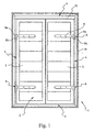
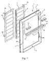
- 1 denotes overall a support structure for a leaf shutter 2.
- the shutter 2 is of the twin-leaf type and comprises two leaves 3 which are supported so as to be able to rotate with respect to the structure of the building so as to pass from an open configuration into a closed contact configuration where the leaves 3 perform the function of covering/protecting the window or door openings.
- the support structure 1 comprises two facing uprights 4 and 5 and an upper cross-member 6 for connecting together the abovementioned uprights. Together the cross-member 6 and the uprights 4 and 5 define a frame able to be fixed to the masonry structure of the building in the region of a window or door opening. More specifically, the support structure 1 is suitable for being inserted directly inside the abovementioned opening, so as to be substantially flush with the outer wall which bounds the opening.
- the support structure 1 may also comprise a bottom cross-member 7 for connecting together the uprights 4 and 5, which helps increase the rigidity of the structure.
- the support structure 1 has a quadrilateral configuration.
- the presence of the bottom cross-member 6, although it allows an increase in the structural rigidity of the support structure, may be undesirable for some applications, for example in the case of French windows, since it may hinder access.
- the uprights 4 and 5 and the upper cross-member 6 and bottom cross-member 7 may advantageously be made of aluminium or other material which can be easily extruded, as well as wood or plastic.
- the support structure 1 comprises hinges 8 which are associated with the uprights 4 and 5 in order to allow the abovementioned rotation of the leaves 3 of the shutter 2.
- the embodiment shown in the figures relates to a twin-leaf shutter such that both the upright 4 and the upright 5 have hinges 8 for allowing rotation of the respective shutter 2 supported by them.
- the shutter has only one leaf, which may be divided into two or more parts, it is evident that only one of the two side uprights will be provided with respective hinges.
- each leaf 3 of the shutter 2 is supported rotatably with respect to the respective upright 4 or 5 by means of two hinges 8, it also being possible to envisage a greater number of hinges, for example three or four hinges for leaves with greater dimensions and/or weight.
- Each hinge 8 comprises a fixed part 8a fixed to the respective upright 4,5 and a movable part 8b which is associated with the fixed part 8a so as to be able to rotate about a hinging axis which is conventional per se.
- the movable hinge part 8b is intended to be fixed to a respective leaf of a shutter so as to ensure the rotational supporting of the leaf with respect to the upright between a closed position in contact with the support structure 1 ( Figures 1 and 2 ) and an open position.
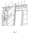
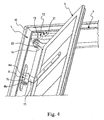
- Figures 3 , 4 and 5 show a condition where one of the two leaves is in the partially open configuration.
- the support structure 1 envisages locating means against which the leaves 3 of the shutter 2 come into contact, defining the abovementioned closed contact position.
- the fixed hinge part 8a is fixed to the respective upright by means of a fixing bracket 14, while the movable hinge part 8b is in turn rigidly connected to a further fixing bracket 15 designed to allow fixing to the leaf 3.
- the hinges 8 fixed to the same upright 4 or 5 are positioned aligned with each other so as to have their respective axes of rotation substantially aligned with each other along the same straight line X-X intersecting the upper cross-member 6.
- the upper cross-member 6 defines a housing 9 for housing actuating means 12 suitable for rotationally actuating the leaves 3 of the shutter 2 between the closed position in contact with the support structure 1 ( Figure 1 ) and an open position.
- the abovementioned actuating means 12 have a rotating shaft 13 which extends along the abovementioned straight line X-X in alignment with the axes of the hinges 8 and is able to cause rotation of the respective leaf 3.
- the support structure 1 comprises two respective and separate actuating means 12 which are positioned at the opposite side ends of the upper cross-member 6, each having a respective rotating shaft 13 positioned and extending in the manner described above.
- each rotating shaft 13 of the actuating means 12 projects from the respective opening 11 so as to be able to transmit the rotational movement to the respective leaf 3.
- each leaf 3 of the shutter 2 has, fixed thereto, along the upper edge close to the respective upright 4,5, a bracket 20 - in the example L-shaped - which is designed to engage with the free end of the respective rotating shaft 13 in the form of a prismatic connection able to transfer the rotational movement of the rotating shaft 13 to the bracket 20 and, consequently, to the respective leaf 3.
- the free end of the rotating shaft 13 terminates in a rectangular end lug, while the bracket 20 has an end fork able to engage with this end lug.
- the abovementioned bracket 20 may have an end which is formed so as to be inserted inside the respective opening 11 of the casing 10 and be rotationally actuated there by the actuating means 12.
- actuating means 12 in particular the electric motor incorporated in them, may advantageously be managed by an electronic module, the latter being controlled by means of control signals (electric signals of the type which can be transmitted via radio frequency, infrared or cable), and by end-of-travel sensors.
- control signals electrical signals of the type which can be transmitted via radio frequency, infrared or cable
- the control signals may, for example, be generated by a user who presses the keys forming part of a remote control or a control switch.
- the uprights 4 and 5 have a box-like form, as do the upper cross-member 6 and the bottom cross-member 7 where present.
- the connection between an upright and a cross-member at a corner may be performed, in a manner conventional per se, by means of reinforcing angle-pieces which engage with inner end portions of the abovementioned box-like structures.
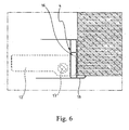
- the uprights 4 and 5 have a respective recess 16 in the inner wall in the vicinity of the top end, more precisely at a predefined distance from the upper cross-member 6.
- This recess is such as to allow the built-in mounting of a portion of the actuating means 12 so as to obtain positioning of these motor means which is as close as possible to the outer side of the support structure, namely in the vicinity of the masonry structure.
- the upper cross-member 6 also has a respective recess 21 (shown in Figure 5 ) which is formed in its bottom wall at the opposite ends.
- This recess 21 allows built-in mounting of a portion of the actuating means 12 so as to obtain positioning of these motor means which is as high up as possible.
- the support structure 1 comprises a perimetral flange 18 and a corresponding perimetral flange 19 projecting outwards along the outer and inner edges of the support structure 1, respectively.
- the abovementioned perimetral flanges 18 and 19 are able to ensure that there is correct contact between the support structure 1 and the masonry structure portion of the building to which this structure is applied, acting as a barrier against the possible infiltration of water, rain and the like.
- the perimetral flange 18 is able to project a few centimetres beyond the edge of the window or door opening inside which the support structure 1 is arranged.
- the support structure 1 During use of the support structure 1, the latter is fixed, in a manner conventional per se, for example by means of plugs, to the masonry structure of the building, after it has been correctly positioned inside the opening, for example of a window.
- the structure 1 therefore ensures correct positioning of the leaves 3 and the correct closure of the window opening when both the leaves 3 are in the closed contact configuration ( Figures 1 and 2 ). Moreover the presence of the support structure 1 ensures that the two opposite leaves 3 of the shutter 2 overlap with each other in the closed condition in the correct manner.
- the actuating means 12 In the case where it is required to automate operation of the shutter 2, it is sufficient to add the actuating means 12, if necessary also at a later date after initial installation of the support structure. To do so, it is sufficient to house the actuating means 12 in the housing 11 provided in the upper cross-member, ensuring that the end lugs of the rotating shafts 13 project from the respective openings in the casing 10. Then the bracket 20 need merely be mounted on each leaf 3 of the shutter, ensuring that the end fork of each bracket engages with the end lug of the respective rotating shaft.
- Figure 8 shows a support structure 1 according to the invention designed to support a rotating shutter 2 of the so-called Vicenza type.
- Figure 8 shows a situation where the casing 10 of the upper cross-member 8 has been removed and the Vicenza type leaf 3, composed of two half-leaves 3a and 3b hinged together, is in a partly open position.
- the half-leaf 3b not directly hinged with the upright 4, is guided along an upper track supported by the upper cross-member 6 in a manner conventional per se.
- the structural and functional features of the support structure 1, in particular with reference to positioning of the hinging axes with respect to the upper cross-member, are such that it is possible to perform automation of the leaf shutters without having to provide hinged lever systems since, as described above, the bracket rigidly fixed to each leaf 3 is directly actuated by a rotating shaft of the actuating means.
- the support structure for leaf shutters according to the invention it is possible to fulfil the abovementioned requirements, without encountering the problems associated with the difficulty of positioning the hinges with respect to the masonry structure or the presence of the hinged lever systems.
Landscapes
- Chemical & Material Sciences (AREA)
- Oil, Petroleum & Natural Gas (AREA)
- Engineering & Computer Science (AREA)
- Chemical Kinetics & Catalysis (AREA)
- General Chemical & Material Sciences (AREA)
- Organic Chemistry (AREA)
- Operating, Guiding And Securing Of Roll- Type Closing Members (AREA)
- Moulding By Coating Moulds (AREA)
- Forklifts And Lifting Vehicles (AREA)
- Materials For Medical Uses (AREA)
Applications Claiming Priority (2)
| Application Number | Priority Date | Filing Date | Title |
|---|---|---|---|
| IT000159A ITMI20070159A1 (it) | 2007-01-31 | 2007-01-31 | Struttura di supporto per imposte a rotazione. |
| PCT/IB2008/000138 WO2008093189A1 (en) | 2007-01-31 | 2008-01-23 | Support structure for rotating shutters |
Publications (2)
| Publication Number | Publication Date |
|---|---|
| EP2109706A1 EP2109706A1 (en) | 2009-10-21 |
| EP2109706B1 true EP2109706B1 (en) | 2012-02-29 |
Family
ID=39370986
Family Applications (1)
| Application Number | Title | Priority Date | Filing Date |
|---|---|---|---|
| EP08702291A Not-in-force EP2109706B1 (en) | 2007-01-31 | 2008-01-23 | Support structure for rotating shutters |
Country Status (4)
| Country | Link |
|---|---|
| EP (1) | EP2109706B1 (it) |
| AT (1) | ATE547583T1 (it) |
| IT (1) | ITMI20070159A1 (it) |
| WO (1) | WO2008093189A1 (it) |
Families Citing this family (3)
| Publication number | Priority date | Publication date | Assignee | Title |
|---|---|---|---|---|
| FR2958316B1 (fr) * | 2010-04-06 | 2015-03-13 | Somfy Sas | Procede de configuration d'un dispositif de motorisation d'une installation domotique munie d'un volet et dispositif de motorisation d'une installation domotique munie d'un volet |
| ES2911424T3 (es) | 2015-11-30 | 2022-05-19 | Bhg | Bastidor para persiana abatible |
| FR3044346A1 (fr) * | 2015-11-30 | 2017-06-02 | Bubendorff | Chassis pour volet battant. |
Family Cites Families (4)
| Publication number | Priority date | Publication date | Assignee | Title |
|---|---|---|---|---|
| FR2486139A1 (fr) * | 1980-07-04 | 1982-01-08 | Scheuer Paul | Dispositif d'ouverture/fermeture de battants de volets de fenetres ou porte-fenetres a partir de l'interieur du batiment |
| DE9418875U1 (de) * | 1994-11-24 | 1995-01-26 | Hofstetter, Hermann, 83093 Bad Endorf | Motorbetriebene, klappenförmige Vorrichtung zum Verschließen von Öffnungen, insbesondere von Fenstern oder Türen von außen |
| FR2807781B1 (fr) | 2000-04-14 | 2003-09-05 | Voltec | Bati dormant comprenant un ensemble d'entrainement de volets battants |
| FR2877984A1 (fr) * | 2004-11-16 | 2006-05-19 | Joseph Audureau | Procede d'encastrement d'un mecanisme de manoeuvre de volet battant dans le linteau d'une baie. |
-
2007
- 2007-01-31 IT IT000159A patent/ITMI20070159A1/it unknown
-
2008
- 2008-01-23 WO PCT/IB2008/000138 patent/WO2008093189A1/en not_active Ceased
- 2008-01-23 AT AT08702291T patent/ATE547583T1/de active
- 2008-01-23 EP EP08702291A patent/EP2109706B1/en not_active Not-in-force
Also Published As
| Publication number | Publication date |
|---|---|
| EP2109706A1 (en) | 2009-10-21 |
| WO2008093189A1 (en) | 2008-08-07 |
| ITMI20070159A1 (it) | 2008-08-01 |
| ATE547583T1 (de) | 2012-03-15 |
Similar Documents
| Publication | Publication Date | Title |
|---|---|---|
| RU2184828C1 (ru) | Открываемое окно с облицовочными элементами оконной коробки и створки | |
| EP2364392B1 (en) | Roof window, in particular a smoke extraction window, with a pivot sash | |
| EP3615753B1 (en) | Swing door operator system | |
| EP4390030B1 (en) | Roof window with a lifting device and method of assembling a lifting device | |
| EP2109706B1 (en) | Support structure for rotating shutters | |
| RU2494211C2 (ru) | Система цельностеклянной двери с защитой от защемления пальцев | |
| AU2017360021B2 (en) | Door driving mechanism for a swing door | |
| EP4170121A1 (en) | Covering box and hood for roller elements | |
| US4044812A (en) | Remotely operated window shutters | |
| EP3666996B1 (en) | Security device for closing two hinged elements, door opener and door comprising said device | |
| KR101656640B1 (ko) | 가변 회동타입 안전 오르내리창 | |
| WO2005028793A1 (en) | Window or door structure with a locking tap | |
| KR20060116144A (ko) | 도어의 열림각을 조정 및 제어할 수 있는 경첩 | |
| JP4452151B2 (ja) | 枠装置 | |
| EP3730716B1 (en) | Roof window with improved covering arrangement and method of providing a roof window with improved covering arrangement | |
| EP3252250B1 (en) | A roof window with an improved hinge and covering assembly, and a method of providing such a hinge and covering assembly | |
| CN217681515U (zh) | 一种新型联动口袋锁纱窗 | |
| EP3623560B1 (en) | Displacement system comprising locking system | |
| KR200391475Y1 (ko) | 도어의 열림각을 조정 및 제어할 수 있는 경첩 | |
| KR0122014Y1 (ko) | 노출되지 않는 도어용 힌지 조립체 | |
| JP2002115447A (ja) | 建物の窓構造 | |
| AU2002300001B9 (en) | Dual hinged frame | |
| KR200339803Y1 (ko) | 편심회전축을 갖는 방화문용 무돌출 경첩 | |
| KR20160004344U (ko) | 한옥식 창호용 경첩 | |
| JP3833644B2 (ja) | 出窓 |
Legal Events
| Date | Code | Title | Description |
|---|---|---|---|
| PUAI | Public reference made under article 153(3) epc to a published international application that has entered the european phase |
Free format text: ORIGINAL CODE: 0009012 |
|
| 17P | Request for examination filed |
Effective date: 20090721 |
|
| AK | Designated contracting states |
Kind code of ref document: A1 Designated state(s): AT BE BG CH CY CZ DE DK EE ES FI FR GB GR HR HU IE IS IT LI LT LU LV MC MT NL NO PL PT RO SE SI SK TR |
|
| 17Q | First examination report despatched |
Effective date: 20100308 |
|
| DAX | Request for extension of the european patent (deleted) | ||
| GRAP | Despatch of communication of intention to grant a patent |
Free format text: ORIGINAL CODE: EPIDOSNIGR1 |
|
| GRAS | Grant fee paid |
Free format text: ORIGINAL CODE: EPIDOSNIGR3 |
|
| GRAA | (expected) grant |
Free format text: ORIGINAL CODE: 0009210 |
|
| AK | Designated contracting states |
Kind code of ref document: B1 Designated state(s): AT BE BG CH CY CZ DE DK EE ES FI FR GB GR HR HU IE IS IT LI LT LU LV MC MT NL NO PL PT RO SE SI SK TR |
|
| REG | Reference to a national code |
Ref country code: GB Ref legal event code: FG4D Ref country code: CH Ref legal event code: EP |
|
| REG | Reference to a national code |
Ref country code: AT Ref legal event code: REF Ref document number: 547583 Country of ref document: AT Kind code of ref document: T Effective date: 20120315 |
|
| REG | Reference to a national code |
Ref country code: IE Ref legal event code: FG4D |
|
| REG | Reference to a national code |
Ref country code: DE Ref legal event code: R096 Ref document number: 602008013748 Country of ref document: DE Effective date: 20120426 |
|
| REG | Reference to a national code |
Ref country code: NL Ref legal event code: VDEP Effective date: 20120229 |
|
| LTIE | Lt: invalidation of european patent or patent extension |
Effective date: 20120229 |
|
| PG25 | Lapsed in a contracting state [announced via postgrant information from national office to epo] |
Ref country code: NL Free format text: LAPSE BECAUSE OF FAILURE TO SUBMIT A TRANSLATION OF THE DESCRIPTION OR TO PAY THE FEE WITHIN THE PRESCRIBED TIME-LIMIT Effective date: 20120229 Ref country code: IS Free format text: LAPSE BECAUSE OF FAILURE TO SUBMIT A TRANSLATION OF THE DESCRIPTION OR TO PAY THE FEE WITHIN THE PRESCRIBED TIME-LIMIT Effective date: 20120629 Ref country code: HR Free format text: LAPSE BECAUSE OF FAILURE TO SUBMIT A TRANSLATION OF THE DESCRIPTION OR TO PAY THE FEE WITHIN THE PRESCRIBED TIME-LIMIT Effective date: 20120229 Ref country code: LT Free format text: LAPSE BECAUSE OF FAILURE TO SUBMIT A TRANSLATION OF THE DESCRIPTION OR TO PAY THE FEE WITHIN THE PRESCRIBED TIME-LIMIT Effective date: 20120229 Ref country code: NO Free format text: LAPSE BECAUSE OF FAILURE TO SUBMIT A TRANSLATION OF THE DESCRIPTION OR TO PAY THE FEE WITHIN THE PRESCRIBED TIME-LIMIT Effective date: 20120529 |
|
| PG25 | Lapsed in a contracting state [announced via postgrant information from national office to epo] |
Ref country code: PT Free format text: LAPSE BECAUSE OF FAILURE TO SUBMIT A TRANSLATION OF THE DESCRIPTION OR TO PAY THE FEE WITHIN THE PRESCRIBED TIME-LIMIT Effective date: 20120629 Ref country code: BE Free format text: LAPSE BECAUSE OF FAILURE TO SUBMIT A TRANSLATION OF THE DESCRIPTION OR TO PAY THE FEE WITHIN THE PRESCRIBED TIME-LIMIT Effective date: 20120229 Ref country code: GR Free format text: LAPSE BECAUSE OF FAILURE TO SUBMIT A TRANSLATION OF THE DESCRIPTION OR TO PAY THE FEE WITHIN THE PRESCRIBED TIME-LIMIT Effective date: 20120530 Ref country code: FI Free format text: LAPSE BECAUSE OF FAILURE TO SUBMIT A TRANSLATION OF THE DESCRIPTION OR TO PAY THE FEE WITHIN THE PRESCRIBED TIME-LIMIT Effective date: 20120229 Ref country code: LV Free format text: LAPSE BECAUSE OF FAILURE TO SUBMIT A TRANSLATION OF THE DESCRIPTION OR TO PAY THE FEE WITHIN THE PRESCRIBED TIME-LIMIT Effective date: 20120229 |
|
| REG | Reference to a national code |
Ref country code: AT Ref legal event code: MK05 Ref document number: 547583 Country of ref document: AT Kind code of ref document: T Effective date: 20120229 |
|
| PG25 | Lapsed in a contracting state [announced via postgrant information from national office to epo] |
Ref country code: CY Free format text: LAPSE BECAUSE OF FAILURE TO SUBMIT A TRANSLATION OF THE DESCRIPTION OR TO PAY THE FEE WITHIN THE PRESCRIBED TIME-LIMIT Effective date: 20120229 |
|
| PG25 | Lapsed in a contracting state [announced via postgrant information from national office to epo] |
Ref country code: SE Free format text: LAPSE BECAUSE OF FAILURE TO SUBMIT A TRANSLATION OF THE DESCRIPTION OR TO PAY THE FEE WITHIN THE PRESCRIBED TIME-LIMIT Effective date: 20120229 Ref country code: CZ Free format text: LAPSE BECAUSE OF FAILURE TO SUBMIT A TRANSLATION OF THE DESCRIPTION OR TO PAY THE FEE WITHIN THE PRESCRIBED TIME-LIMIT Effective date: 20120229 Ref country code: EE Free format text: LAPSE BECAUSE OF FAILURE TO SUBMIT A TRANSLATION OF THE DESCRIPTION OR TO PAY THE FEE WITHIN THE PRESCRIBED TIME-LIMIT Effective date: 20120229 Ref country code: DK Free format text: LAPSE BECAUSE OF FAILURE TO SUBMIT A TRANSLATION OF THE DESCRIPTION OR TO PAY THE FEE WITHIN THE PRESCRIBED TIME-LIMIT Effective date: 20120229 Ref country code: SI Free format text: LAPSE BECAUSE OF FAILURE TO SUBMIT A TRANSLATION OF THE DESCRIPTION OR TO PAY THE FEE WITHIN THE PRESCRIBED TIME-LIMIT Effective date: 20120229 Ref country code: RO Free format text: LAPSE BECAUSE OF FAILURE TO SUBMIT A TRANSLATION OF THE DESCRIPTION OR TO PAY THE FEE WITHIN THE PRESCRIBED TIME-LIMIT Effective date: 20120229 Ref country code: PL Free format text: LAPSE BECAUSE OF FAILURE TO SUBMIT A TRANSLATION OF THE DESCRIPTION OR TO PAY THE FEE WITHIN THE PRESCRIBED TIME-LIMIT Effective date: 20120229 |
|
| PG25 | Lapsed in a contracting state [announced via postgrant information from national office to epo] |
Ref country code: SK Free format text: LAPSE BECAUSE OF FAILURE TO SUBMIT A TRANSLATION OF THE DESCRIPTION OR TO PAY THE FEE WITHIN THE PRESCRIBED TIME-LIMIT Effective date: 20120229 |
|
| PLBE | No opposition filed within time limit |
Free format text: ORIGINAL CODE: 0009261 |
|
| STAA | Information on the status of an ep patent application or granted ep patent |
Free format text: STATUS: NO OPPOSITION FILED WITHIN TIME LIMIT |
|
| PG25 | Lapsed in a contracting state [announced via postgrant information from national office to epo] |
Ref country code: AT Free format text: LAPSE BECAUSE OF FAILURE TO SUBMIT A TRANSLATION OF THE DESCRIPTION OR TO PAY THE FEE WITHIN THE PRESCRIBED TIME-LIMIT Effective date: 20120229 |
|
| 26N | No opposition filed |
Effective date: 20121130 |
|
| REG | Reference to a national code |
Ref country code: DE Ref legal event code: R097 Ref document number: 602008013748 Country of ref document: DE Effective date: 20121130 |
|
| PG25 | Lapsed in a contracting state [announced via postgrant information from national office to epo] |
Ref country code: ES Free format text: LAPSE BECAUSE OF FAILURE TO SUBMIT A TRANSLATION OF THE DESCRIPTION OR TO PAY THE FEE WITHIN THE PRESCRIBED TIME-LIMIT Effective date: 20120609 |
|
| PG25 | Lapsed in a contracting state [announced via postgrant information from national office to epo] |
Ref country code: BG Free format text: LAPSE BECAUSE OF FAILURE TO SUBMIT A TRANSLATION OF THE DESCRIPTION OR TO PAY THE FEE WITHIN THE PRESCRIBED TIME-LIMIT Effective date: 20120529 |
|
| PG25 | Lapsed in a contracting state [announced via postgrant information from national office to epo] |
Ref country code: MC Free format text: LAPSE BECAUSE OF NON-PAYMENT OF DUE FEES Effective date: 20130131 |
|
| REG | Reference to a national code |
Ref country code: CH Ref legal event code: PL |
|
| GBPC | Gb: european patent ceased through non-payment of renewal fee |
Effective date: 20130123 |
|
| REG | Reference to a national code |
Ref country code: IE Ref legal event code: MM4A |
|
| PG25 | Lapsed in a contracting state [announced via postgrant information from national office to epo] |
Ref country code: DE Free format text: LAPSE BECAUSE OF NON-PAYMENT OF DUE FEES Effective date: 20130801 Ref country code: CH Free format text: LAPSE BECAUSE OF NON-PAYMENT OF DUE FEES Effective date: 20130131 Ref country code: LI Free format text: LAPSE BECAUSE OF NON-PAYMENT OF DUE FEES Effective date: 20130131 |
|
| REG | Reference to a national code |
Ref country code: DE Ref legal event code: R119 Ref document number: 602008013748 Country of ref document: DE Effective date: 20130801 |
|
| PG25 | Lapsed in a contracting state [announced via postgrant information from national office to epo] |
Ref country code: GB Free format text: LAPSE BECAUSE OF NON-PAYMENT OF DUE FEES Effective date: 20130123 |
|
| PG25 | Lapsed in a contracting state [announced via postgrant information from national office to epo] |
Ref country code: IE Free format text: LAPSE BECAUSE OF NON-PAYMENT OF DUE FEES Effective date: 20130123 |
|
| PG25 | Lapsed in a contracting state [announced via postgrant information from national office to epo] |
Ref country code: MT Free format text: LAPSE BECAUSE OF FAILURE TO SUBMIT A TRANSLATION OF THE DESCRIPTION OR TO PAY THE FEE WITHIN THE PRESCRIBED TIME-LIMIT Effective date: 20120229 |
|
| PG25 | Lapsed in a contracting state [announced via postgrant information from national office to epo] |
Ref country code: TR Free format text: LAPSE BECAUSE OF FAILURE TO SUBMIT A TRANSLATION OF THE DESCRIPTION OR TO PAY THE FEE WITHIN THE PRESCRIBED TIME-LIMIT Effective date: 20120229 |
|
| PG25 | Lapsed in a contracting state [announced via postgrant information from national office to epo] |
Ref country code: HU Free format text: LAPSE BECAUSE OF FAILURE TO SUBMIT A TRANSLATION OF THE DESCRIPTION OR TO PAY THE FEE WITHIN THE PRESCRIBED TIME-LIMIT; INVALID AB INITIO Effective date: 20080123 Ref country code: LU Free format text: LAPSE BECAUSE OF NON-PAYMENT OF DUE FEES Effective date: 20130123 |
|
| REG | Reference to a national code |
Ref country code: FR Ref legal event code: PLFP Year of fee payment: 9 |
|
| PGFP | Annual fee paid to national office [announced via postgrant information from national office to epo] |
Ref country code: IT Payment date: 20160115 Year of fee payment: 9 |
|
| PGFP | Annual fee paid to national office [announced via postgrant information from national office to epo] |
Ref country code: FR Payment date: 20160126 Year of fee payment: 9 |
|
| REG | Reference to a national code |
Ref country code: FR Ref legal event code: ST Effective date: 20170929 |
|
| PG25 | Lapsed in a contracting state [announced via postgrant information from national office to epo] |
Ref country code: FR Free format text: LAPSE BECAUSE OF NON-PAYMENT OF DUE FEES Effective date: 20170131 |
|
| PG25 | Lapsed in a contracting state [announced via postgrant information from national office to epo] |
Ref country code: IT Free format text: LAPSE BECAUSE OF NON-PAYMENT OF DUE FEES Effective date: 20170123 |