EP2109993B1 - Dispositif et procédé pour coder un bloc de coefficients issus d'une transformée - Google Patents
Dispositif et procédé pour coder un bloc de coefficients issus d'une transformée Download PDFInfo
- Publication number
- EP2109993B1 EP2109993B1 EP07856524A EP07856524A EP2109993B1 EP 2109993 B1 EP2109993 B1 EP 2109993B1 EP 07856524 A EP07856524 A EP 07856524A EP 07856524 A EP07856524 A EP 07856524A EP 2109993 B1 EP2109993 B1 EP 2109993B1
- Authority
- EP
- European Patent Office
- Prior art keywords
- magnitude
- bit
- bits
- predetermined
- magnitude bits
- Prior art date
- Legal status (The legal status is an assumption and is not a legal conclusion. Google has not performed a legal analysis and makes no representation as to the accuracy of the status listed.)
- Not-in-force
Links
Images


Classifications
-
- G—PHYSICS
- G06—COMPUTING OR CALCULATING; COUNTING
- G06T—IMAGE DATA PROCESSING OR GENERATION, IN GENERAL
- G06T9/00—Image coding
- G06T9/007—Transform coding, e.g. discrete cosine transform
-
- H—ELECTRICITY
- H04—ELECTRIC COMMUNICATION TECHNIQUE
- H04N—PICTORIAL COMMUNICATION, e.g. TELEVISION
- H04N19/00—Methods or arrangements for coding, decoding, compressing or decompressing digital video signals
- H04N19/10—Methods or arrangements for coding, decoding, compressing or decompressing digital video signals using adaptive coding
- H04N19/102—Methods or arrangements for coding, decoding, compressing or decompressing digital video signals using adaptive coding characterised by the element, parameter or selection affected or controlled by the adaptive coding
- H04N19/13—Adaptive entropy coding, e.g. adaptive variable length coding [AVLC] or context adaptive binary arithmetic coding [CABAC]
-
- H—ELECTRICITY
- H04—ELECTRIC COMMUNICATION TECHNIQUE
- H04N—PICTORIAL COMMUNICATION, e.g. TELEVISION
- H04N19/00—Methods or arrangements for coding, decoding, compressing or decompressing digital video signals
- H04N19/10—Methods or arrangements for coding, decoding, compressing or decompressing digital video signals using adaptive coding
- H04N19/134—Methods or arrangements for coding, decoding, compressing or decompressing digital video signals using adaptive coding characterised by the element, parameter or criterion affecting or controlling the adaptive coding
- H04N19/136—Incoming video signal characteristics or properties
-
- H—ELECTRICITY
- H04—ELECTRIC COMMUNICATION TECHNIQUE
- H04N—PICTORIAL COMMUNICATION, e.g. TELEVISION
- H04N19/00—Methods or arrangements for coding, decoding, compressing or decompressing digital video signals
- H04N19/10—Methods or arrangements for coding, decoding, compressing or decompressing digital video signals using adaptive coding
- H04N19/169—Methods or arrangements for coding, decoding, compressing or decompressing digital video signals using adaptive coding characterised by the coding unit, i.e. the structural portion or semantic portion of the video signal being the object or the subject of the adaptive coding
- H04N19/17—Methods or arrangements for coding, decoding, compressing or decompressing digital video signals using adaptive coding characterised by the coding unit, i.e. the structural portion or semantic portion of the video signal being the object or the subject of the adaptive coding the unit being an image region, e.g. an object
- H04N19/176—Methods or arrangements for coding, decoding, compressing or decompressing digital video signals using adaptive coding characterised by the coding unit, i.e. the structural portion or semantic portion of the video signal being the object or the subject of the adaptive coding the unit being an image region, e.g. an object the region being a block, e.g. a macroblock
-
- H—ELECTRICITY
- H04—ELECTRIC COMMUNICATION TECHNIQUE
- H04N—PICTORIAL COMMUNICATION, e.g. TELEVISION
- H04N19/00—Methods or arrangements for coding, decoding, compressing or decompressing digital video signals
- H04N19/10—Methods or arrangements for coding, decoding, compressing or decompressing digital video signals using adaptive coding
- H04N19/169—Methods or arrangements for coding, decoding, compressing or decompressing digital video signals using adaptive coding characterised by the coding unit, i.e. the structural portion or semantic portion of the video signal being the object or the subject of the adaptive coding
- H04N19/184—Methods or arrangements for coding, decoding, compressing or decompressing digital video signals using adaptive coding characterised by the coding unit, i.e. the structural portion or semantic portion of the video signal being the object or the subject of the adaptive coding the unit being bits, e.g. of the compressed video stream
-
- H—ELECTRICITY
- H04—ELECTRIC COMMUNICATION TECHNIQUE
- H04N—PICTORIAL COMMUNICATION, e.g. TELEVISION
- H04N19/00—Methods or arrangements for coding, decoding, compressing or decompressing digital video signals
- H04N19/42—Methods or arrangements for coding, decoding, compressing or decompressing digital video signals characterised by implementation details or hardware specially adapted for video compression or decompression, e.g. dedicated software implementation
-
- H—ELECTRICITY
- H04—ELECTRIC COMMUNICATION TECHNIQUE
- H04N—PICTORIAL COMMUNICATION, e.g. TELEVISION
- H04N19/00—Methods or arrangements for coding, decoding, compressing or decompressing digital video signals
- H04N19/42—Methods or arrangements for coding, decoding, compressing or decompressing digital video signals characterised by implementation details or hardware specially adapted for video compression or decompression, e.g. dedicated software implementation
- H04N19/423—Methods or arrangements for coding, decoding, compressing or decompressing digital video signals characterised by implementation details or hardware specially adapted for video compression or decompression, e.g. dedicated software implementation characterised by memory arrangements
-
- H—ELECTRICITY
- H04—ELECTRIC COMMUNICATION TECHNIQUE
- H04N—PICTORIAL COMMUNICATION, e.g. TELEVISION
- H04N19/00—Methods or arrangements for coding, decoding, compressing or decompressing digital video signals
- H04N19/90—Methods or arrangements for coding, decoding, compressing or decompressing digital video signals using coding techniques not provided for in groups H04N19/10-H04N19/85, e.g. fractals
- H04N19/91—Entropy coding, e.g. variable length coding [VLC] or arithmetic coding
Definitions
- the present invention relates to the coding of transform coefficient blocks, e.g. an image, such as occurs in the course of the digital image compression method according to the JPEG2000 standard.
- the steps of the JPEG2000 encoding process include optionally splitting the image into so-called tiles, ie rectangular image areas, a DC signal level shift, an optional transformation of the color components, performing a discrete wavelet transform, a scalar quantization of wavelet coefficients, an array of quantized ones Wavelet coefficients in two-dimensional fields, so-called "code blocks", a block coding comprising a so-called “coefficient bit-modeling process” and an arithmetic coding operation, and arranging the coded code block data into a standard-compliant coding stream.
- the steps are described in Christopoulos et al .: The JPEG2000 Still Image Coding System: An Overview, IEEE Transactions on Consumer Electronics, Vol. 46, No. 4, pp. 1103-1127, November 2000 ,
- a code block is decomposed into so-called magnitude bit planes which are arranged in order from the MSBs or the most significant bits to the LSBs and the least significant bits, respectively, and associated sign bits which are separately handled . to be viewed as.
- Each amount bit-plane is modulated in a sequence of three coding passes, with the exception of the first bit-plane, which has only one coding pass is modulated.
- These coding passes pass through the bits of an amount bit plane in a particular order. It starts with the bit of the position in the top left corner, then three bits underneath, before jumping one column to the right. This creates a so-called stripe or the width of the code block and the height of four coefficients. After one code block has been processed in a horizontal direction, the next stripe is processed four coefficient positions deeper, and so on.
- ISO / IEC15444-1 describes in more detail whether and which coding scheme is used during a coding pass. In particular, this decision is made on a coefficient-by-coefficient basis. In other words, only certain coefficients are modulated during the first coding pass. Among the remaining coefficients, the second coding pass also encodes a part. The remainder is modeled by the third coding pass. Which coefficient belongs to which coding pass depends i.a. depending on whether the respective coefficient is significant or on the significance of its direct neighbors.
- ISO / IEC 15444-1 hereafter referred to as the standard, defines a binary status variable for each coefficient in a code block, the so-called “significance status". Initially initialized to "insignificant”, it changes to "significant" at the magnitude bit-plane at which a set bit of the coefficient is to be modeled for the first time and thus remains set until the end of the modeling of that code block.
- one data bit is generated together with one context index each.
- This context index results primarily from the significance status variables of the coefficient and its neighbors.
- the sign bit of the current coefficient is also to be modeled together with a context index which, in turn, depends on the significance status variables and the signs of its neighbors.
- a so-called "magnitude refinement" or MR coding scheme or the second coding pass additionally evaluates whether this schema has already been applied to previous bit planes on the coefficients to be modeled, or for the first time.
- the downstream arithmetic encoder awaits the bit-context pairs in the order determined in the manner described above.
- bit-context pairs are to be encoded by the arithmetic encoder according to the standard results in a sequential sequence with respect to the encoding passes as described above, and in particular also by software Implementations is complied with.
- Implementations in hardware can achieve a higher encoding speed. For example, multiple blocks of code can be independently coded simultaneously by instantiating multiple block encoders in parallel. However, this represents a huge resource consumption, such as with regard to the required transistors on an integrated circuit or with regard to the gate equivalents in a FPGA (Field Programmable Gate Array).
- FPGA Field Programmable Gate Array
- a buffer is provided for buffering updated significance status variables between a processing unit which handles the first coding pass and a second processing unit which is responsible for the coding passes 2 and 3.
- the object of the present invention is to provide a method and an apparatus for coding a block of transform coefficients, such as e.g. those of an image that allow for more effective implementation in hardware.
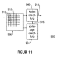
- an apparatus for coding a block of transform coefficients comprises a precoder for traversing the magnitude bits of a predetermined one of the magnitude bit planes into tuples of a plurality of each adjacent magnitude bits and encoding predetermined ones of the magnitude bits of the tuples into data words such that a predetermined one Magnitude bit is coded together with an associated sign bit in one of the data words, or that a predetermined magnitude bit is coded together with another predetermined magnitude bit of the same tuple in one of the data words, a data word buffer for latching the data words, and an entropy coder for coding the data words (from the Data word buffer in a coded data stream.
- a key idea of the first aspect is that by using a precoder, when passing through the magnitude bits of a predetermined magnitude bit plane in tuples of a respective plurality of adjacent magnitude bits, predetermined ones of the magnitude bits of the tuples, but together with one sign bit or several together into one data word and a buffer for the data words connected between the precoder on one side and an entropy encoder on the other side, a faster processing or coding can be achieved.
- the independence of the encoder operation from the entropy encoder operation also allows the entropy encoder to encode, for example, data words of other precoders that are responsible for other predetermined magnitude bits while the precoder is already going through a next magnitude bit-plane.
- the precoder also codes a corresponding sign bit into a data word together with a predetermined magnitude bit, so that the data word has, for example, a partial data word for the magnitude bit and a partial data word the associated sign bit.
- the two processes can thus be precoded parallel to one another in one clock cycle.
- the entropy coder may or may not reconstruct and entropy-code the magnitude bit from the data word in the buffer and thereafter perform the entropy coding of the sign bit depending on the significance of the magnitude bit just encoded.
- the precoder when passing through the predetermined magnitude bits, performs the precoding so that at least two predetermined magnitude bits within a tuple are encoded in a data word.
- the precoder has, for example, for each magnitude bit in a tuple, a precoder unit for encoding the relevant magnitude bits into a partial data word, which are included together in a data word for the tuple, so that in turn all processing is carried out in parallel.
- an apparatus for coding a block of transform coefficients wherein the transform coefficients are each represented by a plurality of magnitude bits, such that they define a sequence of magnitude bit-planes, an encoder for sweeping the magnitude bits of a predetermined one of the magnitude bit-planes and encoding predetermined ones of the magnitude bits of the tuples in a coded data stream, wherein the coding means a latch 106; a bit extractor 104 for, upon passing through the magnitude bits, determining first status bits indicative of the significance of the predetermined magnitude bit-plane for the transform coefficients represented by magnitude bits of the predetermined magnitude bit-plane next in order at the earliest according to an order of traversal , from magnitude bits representing the same transform coefficients as the earliest next-ranked magnitude bits, but in more significant bit-planes than the same and filling the cache with the determined first status bits; and an encoder for encoding the predetermined magnitude bits into the encoded data stream using the first status bits in the buffer.
- One insight of the second aspect is that a more efficient implementation of the transform coefficient block coder is enabled when an encoder performs the coding of the predetermined magnitude bits into the encoded data stream using status bits in a buffer provided by a bit-extractor on the basis of information are filled, which comprise magnitude bits representing the same transform coefficients as at least next in-line magnitude bits, but at more significant bit-planes than the same.
- the significance information which may be needed by the encoder to decide whether and, if so, which or one of the magnitude bits of the predetermined magnitude bit plane belongs to the predetermined magnitude bits, while passing the magnitude bits only temporarily to store locally near the currently-ranked magnitude bits, thereby eliminating the need for more memory to store the significance information.
- the memory requirement can be kept small, so that conversely turn a more expensive but reversed faster memory technology can be used to store these status bits.
- an update of the content may be made to fill the cache to use this updated content during the encoding.
- the added expense of the logic to continually extract the status information instead of storing and restoring across all bit-planes is relatively small compared to the memory overhead.
- the extraction no time loss since the extraction can be carried out in time parallel to the actual coding.
- an apparatus for coding a block of transform coefficients, wherein the transform coefficients are each represented by a plurality of magnitude bits defining a sequence of magnitude bit planes, comprises coding means for sweeping the magnitude bits of a predetermined one of the magnitude bit planes into tuples of a plurality each of adjacent magnitude bits and encoding predetermined ones of the magnitude bits of the tuples into a coded data stream and predicting means for predicting, and if so, which one or more of the magnitude bits among the adjacent magnitude bits of the predetermined magnitude bit plane, at the earliest next in the series according to an order of sweep pertaining to the predetermined magnitude bits, the encoding means being adapted to perform the coding in dependence on the prediction.
- a key idea of the third aspect is that a more effective implementation in, for example, transform coefficient block encoding hardware can be achieved by providing a predictor which predicts whether and, if so, which one or more of the magnitude bits among the adjacent magnitude bits of the predetermined ones Amount bit plane of one according to an order of passage at the earliest next in line row tuple belongs to the predetermined amount bit.
- the prediction is based on magnitude bits of the current magnitude bit-plane in tuples that follow the last ranked tuple according to the order of traversal.
- these magnitude bits may be used to provide significance information to modify the tuples following the most recently ranked tuples for the magnitude bits of the tacks indicating the significance of the transform coefficients represented by them with respect to the current magnitude bit-plane.
- the prediction allows the encoder to immediately begin processing the predetermined magnitude bits or the predetermined magnitude bit in the current tuple, respectively, and the encoder may only process processing cycles for processing magnitude bits in requires the tuples that also belong to the predetermined magnitude bits.
- the encoder may be configured to sequentially perform the encoding of the predetermined magnitude bits in the respective tuples, thereby requiring only the least possible number of processing cycles.
- the coding device is suitable for processing all amount bits in a tuple in parallel, but by means of the prediction is able to take into account not only the amount bit values per se in one and the same processing cycle, but also whether the respective magnitude bit or not in the latter case in the same processing cycle to convert the corresponding magnitude bit into a pair of data value and associated coding context having a state which does not occur for magnitude bits not belonging to the predetermined magnitude bits, such as by setting an illegal coding context.
- the predictor allows a faster implementation of coding that requires fewer processing cycles.
- Fig. 1 shows an image compressor 10 as an example of an application in which the embodiments described below can be used advantageously.
- the image compressor 10 of Fig. 1 is designed to be one Source image 12 consisting of, for example, arranged in columns and rows samples or pixel values in a coded data stream or code stream 14 to compress.
- the compressor includes 10 of Fig. 1 for example, a series connection of optionally a tile splitter 16, a DC level shifter 18, optionally a color transformer 20, a spatial spectral decomposition transformer 22, an optional quantizer 24, a block coder 26 and a data arbiter 28.
- the tile splitter shares the image 12 in, for example, rectangular image areas, so-called tiles or tiles.
- the further processing is carried out per tile or tile, so that the further compression in the individual tiles takes place independently of each other.
- the DC level shifter 18 performs a uniform DC shift within each tile over all pixels of the corresponding tile so that, for example, thereafter the average of the pixel values, such as the luminance values, is zero.
- the color transformer 20 optionally performs a color transformation on the pixel values, wherein the color transformation is optional and, of course, takes place only in the case of color images 12.
- the transformer 22 then performs a spatial spectral decomposition per tile.
- the transformation is, for example, a wavelet transformation, more precisely a discrete wavelet transformation, which is applied to each tile individually.
- each tile is decomposed into different resolution levels consisting of subbands of transform coefficients describing frequency characteristics of local areas of each tile.
- the transform coefficients can already be integers.
- the quantizer 24 optionally subjects the transform coefficients to scalar quantization and combines them into code blocks, ie, for example, rectangular arrays of transform coefficients.
- the block coder 26 entropy-codes the transform coefficients bit by bit in the code blocks into data streams, whereupon the data arbiter 28 still properly arranges the arithmetically coded code block data streams to form the code stream 14, such as a JPEG2000 compliant code stream.
- the block coder 26 has, in particular, as shown in FIG Fig. 1 1, a coefficient bit modulator 30 having a downstream arithmetic coder 31 is shown.
- the coefficient bit modulator 30 assigns to the magnitude bits of the coefficients contexts used by the arithmetic coder 32 for arithmetic coding.
- the arithmetic coder 32 is a context-dependent binary arithmetic coder adapted to divide a current interval representing the current state of the arithmetic coder into two halves depending on estimation probabilities for occurrence of each bit value for the next bit to be encoded and to select one among these halves to limit the current interval to that interval, depending on how the actual bit value of the current bit to be coded is, the estimated probabilities being different for each context, and the context by the coefficient bit mapper 30 depending on neighboring significances and / or magnitude bit values and a plurality of possible contexts.
- the encoder may also adaptively adapt the pre-initialized estimates during encoding to the actual probabilities per context.
- the individual magnitude bits of the transform coefficients in one block are arithmetically coded in a predetermined order
- Encode data stream of the arithmetic encoder 32 namely, in particular first bit-level from the most significant bitplane to the least significant bitplane and within those bitplanes by scanning the coefficient magnitude bits in three passes in a fixed scan order, encoding only magnitude bits in each pass that meet certain criteria, in such a way that with the three passes from the arithmetically coded data stream all magnitude bits can be reconstructed.
- Fig. 2 exemplarily a code block of size 3x8.
- each coefficient a to x is represented by n magnitude bits a 1 ... n, ..., x 1 ... x n and a respective sign bit a vz , ..., x vz
- splitting 36 in magnitude bits and sign bits inherently results from the nature of discrete wavelet transform 22 or from quantization 24 (FIG. Fig. 1 ).
- the MSBs or significant amount bits are, for example, the bits a 1 ... X 1 and form a first amount bit plane 38 1 .
- the other magnitude bits can be combined to form corresponding bit planes 38 2 ... 38 n .
- Each bit plane 38 1 ... 38 n and the sign bits 40 thus each form a 3 ⁇ 8 bit array.
- bit plane 38 1 ... 38 n are scanned in four columns or tuples of four magnitude bits adjacent in the column direction from one line end to the other, ie in strips, whereupon the next strip is scanned in the next lines, and within each four column vector or each tuple the magnitude bits are scanned from top to bottom.
- bit planes 38 1 ... 38 n are scanned in four columns or tuples of four magnitude bits adjacent in the column direction from one line end to the other, ie in strips, whereupon the next strip is scanned in the next lines, and within each four column vector or each tuple the magnitude bits are scanned from top to bottom.
- a triple scanning of the magnitude bits of the individual bit planes is now avoided in accordance with the embodiment described below for a block coder 26 in that the amount bits assigned to the respective passes are detected by means of a scan and coded into data words that make up the bit values and the associated contexts whereupon, after being buffered in a buffer, they are encoded in an appropriate series into an arithmetically coded data stream. In this case, a constant lookup in a memory is avoided by the magnitude bits and sign bits are cached.
- Fig. 3 shows a block encoder 100 according to an embodiment of the present invention. It comprises a memory unit 102, a bit extractor 104, a shift register unit 106, a coefficient bit modulator stage 108, a buffer 110 and an arithmetic encoder 112.
- the memory unit 102 is for example a random access memory, such as a RAM, and acts as an interface for obtaining the quantized signed transformation coefficients the code blocks to be coded, such as the code block 34 of Fig. 2 .
- the bit extractor 104 is coupled to the memory 102 in order to be able to execute accesses 114 to the memory contents of the memory unit 102 in order to read magnitude bits and sign bits from the memory unit 102.
- bit extractor 104 is responsible for filling the shift register unit 106 with bits based on the information read from the memory unit 102, which are needed by the coefficient bit modeling stage 108 to make the necessary context settings or precoding. More specifically, in a somewhat more detailed manner below, bit extractor 104 scans the magnitude bit plane amount bits along the prescribed stripe and continuously fills the shift register unit 106 with information during scanning, so that the shift register unit 106, based on its Shift register length, comprising information bits relating to a current portion of the current magnitude bit-plane along the stripes which the coefficient-bit modeling stage 108 currently requires for its context creation.
- the bite extractor 104 forms, for example, the magnitude sum bits and sign bits by mere acquisition of the current bit-plane amount bits 108, simply transfer the sign bits 118 to be resampled, and associate corresponding status bits 120 with appropriate combining and route them to the shift register unit 106 which is dimensioned to hold the individual bits 108, 110, 112 at a depth of a respective suitable number of shift stages, as will be described in more detail below.
- Neighbor bits located at the edge of the code block are padded with zeros, as shown in FIG Fig. 3 is shown as an example for the upper neighbor bits.
- the shift register 106 would each have four registers (shown shaded) together with 14 neighbor registers each for the coefficient bits 108, sign bits 118, and status bits 120.
- the shift register unit 106 may thus have as several shift registers 106 1,2,3,4 each one for the magnitude bits, sign bits and two different status bits which will be described in more detail below, these individual shift registers 106 1 ... 4 are synchronized with each other, so that per shift pulse all register contents at the same time by one horizontal position or by a shift register rank, ie by a 6-he vector in Fig. 3 to be pushed further.
- the coefficient bit modeling stage 108 decomposes into a plurality of bit modeling units 108 1 , 108 2, and 108 3 , the first for Pass 1, the second for Pass 2 and Pass 2, and the third pass 3, respectively.
- Pass 3 is responsible, and will be described in more detail below.
- the individual units 108 1 -108 3 are respectively coupled to respective bit registers of the shift registers 106 1 -106 4 to analyze the corresponding register contents and, for each bit to be modeled, from a current tuple of magnitude bits stored in Fig. 3 the hatched registers correspond to determine whether or not to model according to the respective pass or pass, and if so, with what result.
- the bit modeling units 108 1 -108 3 are in particular designed to generate a correspondingly precoded data word per tuple or per amount bit belonging to the respective pass including control bits explained in more detail below and in respective latches 110 1 , 110 2 and 110 3 of the buffer stage 110 store. Data words belonging to tuples in which there is no magnitude bit associated with the respective pass can be discarded, as will be described below, as well as data words for magnitude bits not associated with the respective pass.
- the bit modeling units 108 1 -108 3 may in particular be designed to set control bits in the data words that can be used by the subsequent arithmetic coding device 112 to store the data words stored in the latches 110 1 -110 3 and the magnitude bits coded in the same the appropriate order and using the right context or under Suspension of the arithmetic coding in another mode, such as a plaintext mode, into the data stream, as will be discussed in more detail below.
- the arithmetic coding device 112 in particular has a pass decision block 122 to which an arithmetic coder 124 is connected downstream.
- the pass decision block 122 functions as an encoder of the precoded data words in the latches 110 1 -110 3 and is coupled thereto with the latter. From these data words, the pass decision block 122 reconstructs the context-related bits and associated context in the individual passes 1, 2 and 3 and Pass 1, Pass 2 and Pass 3, respectively, and routes those pairs in the appropriate order, ie Pass 1 followed by Pass 2 followed by Pass 3, to the arithmetic encoder 124, which forwarded information may include information about bit modes and associated context indices, as well as information about encoding modes to be used by the arithmetic encoder 124 or the like, where the control signals from the decision block 122 to the arithmetic encoder 124 in Fig. 3 generally indicated at 126. In other words, the pass decoder 122 encodes the retrieved data words in the latches 110 back into bit context pairs 126 and supplies them to the downstream arithmetic encoder 124 in a prescribed manner and appropriate representation.
- the bit extractor 104 provides for the filling of the shift register unit 106.
- the bit extractor 104 scans the current amount bit plane in strips.
- the shift register unit 106 can be thought of as being a window that moves across the current amount bit plane along the scan order, with synchronous movement of a corresponding window in the sign bit plane 40 (FIG. Fig. 2 ) and caching associated status bits for these window contents.
- the bit modeling units 108 1 -108 3 require no further information for their work than those in the shift register unit 106, so that lengthy memory accesses 114 to the memory unit 102 are not necessary.
- only one pass through the current amount bit plane is necessary, although the standard, as discussed above, defines three passes for determining the order in which the magnitude bits are to be encoded into the data stream.
- each of the bit modeling units 108 1 -108 3 only takes care of those magnitude bits in the quadruples that belong to their own pass.
- passport 1 takes care of magnitude bits of transform coefficients that are not yet significant, that is, whose magnitude bits in the more significant magnitude bit planes are zero or nonsignificant, but adjacent to transform coefficients that are significant.
- a transform coefficient in a particular magnitude bit-plane is said to be significant if at least one of the magnitude bits in the more significant magnitude bit-planes is 1 and becomes "significant" in a particular magnitude bit-plane if none of the magnitude bits are in the more significant
- An amount bit is said to be significant if it is 1.
- the passport 2 takes care of transformation coefficients in the current amount bitmap already significant.
- pass 3 addresses the remaining magnitude bits, ie the magnitude bits of transform coefficients which are insignificant and did not fall into pass 1.
- the bit modeling units 108 1 -108 3 fill their respective latches 110 1 -110 3 with successive data words which are sequentially read out by the pass selector 122, in magnitude bitwise fashion, that is, beginning with the buffer 110 1 until the last one Data word of the current amount bit plane has been read, then proceeding with the buffer memory 110 2 , until the last data word has been read from the current magnitude bit plane, again followed by the buffer memory 110 3 , until there the last data word has been read out, where exceptionally in the first or most significant amount bit plane equal to the buffer memory 110 3 is started because there is still no transformation coefficient is significant, and thus no amount bit this level may belong to another pass as pass 3.
- the data words are also decoded in the pass decision 122 and converted into corresponding control signals for the arithmetic encoder 124, which forms therefrom a coded data stream for the code block.
- Fig. 4 shows the construction of the bit modeling unit 108 1 . It is responsible for pass 1, ie for the first coding pass, also referred to as "significance propagation pass", because it relates to magnitude bits of transform coefficients which are in the vicinity of already significant transform coefficients and thus are likely to become significantly more significant than those transformation coefficients farther from already significant ones. As mentioned above, the decision as to whether to model a corresponding magnitude bit in the pass 1 pass is based on whether the corresponding coefficient for the current bit-plane is still insignificant and at least one of its direct neighbor coefficients is significant or significant in the course of the first pass becomes.
- the bit modeling unit 108 1 has an analysis prediction unit 200, a magnitude bit precoding unit 202, the latter upstream multiplexers 204, 206, a sign bit precoding unit 208, the latter upstream multiplexers 210, 212, an update demultiplexer 214, a valid bit multiplexer 216, a four bit register 218, a clock counter 220, a Coefficient selector 222 and a control bit control 224, wherein in Fig. 4 for easier understanding even the cache 110 1 and the shift register unit 106 are shown.
- the analysis prediction unit 200 is provided to advance, that is, in advance of pushing the next tuple to be processed into the portion of the shift register 106 where the bit modeling unit 108 1 expects the tuple to be processed, which location in Fig. 4 are shown with hatching to determine which of these magnitude bits belong to pass 1.
- the analysis / prediction unit 200 makes this decision, for example, whenever the shift register unit 106 is executed by the bit extractor 104 (FIG. Fig. 3 ) is refilled, ie at each shift pulse.
- the bit extractor 104 FIG. Fig. 3
- the analysis prediction unit 200 makes the decision on membership or non-membership of the magnitude bits of the 4's vector q m , r m , s m , t m that become the current tuple at the next shift operation in the register unit 106 hatched register area are shifted, where currently the magnitude bits in, j m , k m and l m are located.
- the analysis / prediction unit 200 is coupled to register cells of the register unit 106, to the part 106 2 concerning the magnitude bits, as indicated by an arrow 226, and to the part 106 3 representing the first status bits, as indicated by an arrow 228, the first status bits indicating the significance of corresponding coefficients with respect to the current bit-plane, as will be discussed in more detail below.
- An output of the analysis / prediction unit 200 is followed by the register 218 to obtain from the analysis / prediction unit 200 the result of the prediction in the form of a 4-bit vector, which is represented by an appropriate bit i.sub.i per magnitude bit of the next current tuple ae , j ae , k ae and l ae indicating whether or not the respective magnitude bit q m , r m , s m and t m are to be processed by the bit modeling unit 108 1 in the subsequent shift cycle.
- Both an input of the multiplexer 216 and an input of the coefficient selector 222 are coupled to the register 218.
- the coefficient selector 222 is configured to select, based on the register contents of the register 218, the magnitude bits of the pass 1 to be pre-coded and to communicate this selection in the form of a multiplexer control signal to the multiplexers 210, 212, 204, 206 and 216 and the demultiplexer 214, respectively .
- the analysis / prediction unit 200 also outputs a prediction about the number of magnitude bits associated with pass 1 in the next ranked tuple, namely the clock counter 220, thus at the beginning of each shift cycle and after a shift, respectively in the shift register 106 is pre-initialized to a value corresponding to the number of magnitude bits associated with the pass 1 in the current magnitude bit tuple.
- the clock counter 220 then decrements, for example, its counter content based on a processing clock which it receives from the coefficient selector 222, which in the processing clock sequentially sets the multiplexer signal to the magnitude bits associated with the pass 1 as indicated in the register 218.
- the multiplexer 216 is configured to output the bit indicated by the multiplexer signal from the register 218 as a valid bit to its latch 110 1 depending on the multiplexer signal from the coefficient selector 222.
- the multiplexer 204 is coupled on the input side to specific register cells of the shift register unit from the magnitude bits portion 106 2 and is adapted to receive, dependent on the multiplexer control signal from the coefficient selector 222, a magnitude bit register cell storing the bit indicated by the multiplexer signal Magnitude bit pre-coding unit 202 and optionally an input of the sign bit precoding unit 208 by coupling a corresponding one of the inputs of the multiplexer 204 to a corresponding output of the multiplexer 204 is guided.
- the multiplexer 210 is coupled on the input side with special sign bit cells from the part 106 1 of the shift register unit 106 and designed to receive a corresponding subset of these register contents or sign bits via the output of the multiplexer depending on the multiplexer signal Multiplexer 210 output to another input of the sign bit precoding unit 208.
- the incoming signals are used by the precoder units 208 and 202 to output a pair of data bits 230 and 232 and context index consisting of 2 bits 234 and 236, respectively, the data bit representing the bit value of the sign bit and the magnitude bit of, respectively the multiplexer signal indicates displayed transformation coefficients to be currently processed, while the context index points to the corresponding context to be used respectively.
- the sign bit precoding unit 208 additionally utilizes, in its encoding, a bypass mode bit 240 output from the control bit controller 224 adjacent to a pass end bit 242.
- the meaning of these control bits 240 and 242 will be discussed in more detail below.
- the bits 230, 242 together form a 12-bit word 244 which is input to the latch 210 1 .
- the buffer 110 1 may be formed to cache only data words 244 in which the concurrent valid bit 246 output from the multiplexer 216 indicates that the current multiplexer signal pointed to an amount bit associated with the pass 1.
- the data bit 232 output from the magnitude bit pre-code unit 202 is fed back to an input of the demultiplexer 214.
- the latter is coupled on the output side to register cells from the range 106 3 , namely the one containing the first status bits for the current magnitude bits (hatched), in order to use the data bit 232 for updating the first status bit associated with the magnitude bit, depending on the multiplexer signal which has just been modeled by the magnitude bit pre-encoding unit 202. In this way, namely, the significance of the corresponding coefficient is updated.
- Fig. 8 symbolizes a section of the memory unit 102 (FIG. Fig. 3 ) namely a section of the magnitude bits and sign bits of the transformation coefficients of a code block currently to be coded.
- the individual sign bits and magnitude bits are symbolized by cubes 250 and 252, respectively.
- the sign bits 250 are shown juxtaposed in rows and columns, corresponding to the corresponding transform coefficients in the code block to be coded. Only a portion of the sign bit 250 is shown, a portion of sign bits 250 in a current strip 254 plus the adjacent lines 256 and 258 of the strip above and below. Also, the amount bits 252 of the current bit plane are shown as juxtaposed in rows and columns, again showing only a portion of the current bit plane corresponding to the portion of the sign bit plane, ie, a portion of a corresponding strip 260 having the magnitude bits 252 of the above and below lines 262 and 264. For the sake of completeness it is to be noted that vertically aligned magnitude and sign bits in corresponding rows below lines 254-264 in FIG Fig. 8 should belong to the same transformation coefficients.
- the bit extractor 104 fills the shift register unit 106 with memory accesses 114 (FIG. Fig. 2 ) the latter again with sign bits 250 and magnitude bits 252 from the memory unit 102, Fig. 3 such that there is always a section of the sign bit plane or the current magnitude bit plane in the shift register 106 at any time.
- These cutouts are in Fig. 8 highlighted at 266 and 268.
- a portion of the sign bit array of five consecutive columns and six superimposed rows, namely the four rows of the current stripe 254 and the adjacent rows 256 and 258, is located at the considered time in the portion 106 1 of the shift register unit corresponding manner is located in the part 106 2 of the shift register 106 at any time a section of the current magnitude bit plane of four columns length of six lines 260-264.
- the cutouts 266 and 268 of the sign bits 250 and magnitude bits 252 stored in the rows 106 1 and 106 2 of the shift register unit 106 are aligned such that a transform coefficient for which current magnitude bits 252 are latched in the portion 106 2 , the corresponding sign bit 250 of the respective transformation coefficient is also temporarily stored in the part 106 1 .
- a register cell is provided in the shift register unit for each bit to be stored, which in Fig. 8 also as can be seen by the cubes symbolized in the corresponding sections 266 and 268.
- the register cells of the parts 106 1 and 106 2 are interconnected in such a way that the register contents in Fig.
- the bit extractor 104 is now adapted to perform the filling of the part 106 1 and 106 2 with sign bits 250 and magnitude bits 252, respectively, which relate to an associated column of transform coefficients, so that the offset between the contents of the sign bit part 106 1 and gives the current contents of the magnitude bit contents 106 2 of the shift register unit 106 at the rear shift register end, where sign bits are latched in the portion 106 1 which leave this portion at the next shift operation and for which no more magnitude bits are latched in the portion 106 2 .
- the bit modeling units 108 1 and 108 2 also require status bits for their processing, namely first and second status bits.
- the first status bits each indicate, for a transform coefficient, whether or not it is significant with respect to the current magnitude bit-plane.
- the state of significance of the current magnitude bit-plane for a transform coefficient may change after-or during-virtual-first pass.
- the portion 106 3 of the shift register unit 106 is now dimensioned such that it stores for each of six successive columns of transform coefficients in rows corresponding to rows 260-264 a status bit 274 which is stored in Fig. 8 are also shown as cubes.
- the shift register unit 106 stores in the portion 106 3 at each time first transition coefficient status bits 274 of six adjacent six-row columns, five of which contain the first status bits of transform coefficients, including the sign bits 250 in the portion 266 of the portion 106 1 are included.
- first status bits for transformation coefficients are contained in a 6-column of transformation coefficients, with their sign bits 250 or magnitude bits of the current bit plane, the parts 106 1 and 106 2 of the shift register unit 106 are filled only at the next shift operation.
- the cubes 274 may also be considered as the corresponding register cells interconnected to shift their contents column by column Fig. 8 also from right to left in the same cycle as the other parts 106 1 and 106 2 .
- Filling is also done by bit extractor 104, by a bit combination, such as a logical OR between strings aligned in the significance direction, on the basis of the magnitude bits 276 highlighted in hatching in the more significant ones Amount bit planes as the current magnitude bit plane for transform coefficients located at the positions of column 272 whose current bit plane magnitude bits fill the register cells at the leading end of portion 106 2 of shift register unit 106 only at the next shift pulse.
- the filling process that resulted in the most recent entries in the first status bit part 106 3 is in Fig. 8 indicated by the arrow 278.
- a part 106 4 is also provided in the shift register 106, in which second status bits are stored whose meaning and relevance will become clear from the following description.
- the portion 106 4 stores the second status bits for only one column of transform coefficients, in only four rows corresponding to the rows of the strip 260 and 254, respectively, and the second status bits are also cubed as indicated by reference numeral 280.
- the second status bits 280 are updated so as to be always defined for the transform coefficients whose magnitude bits are latched in the output side column in the stripe 260 to be shifted from the portion 106 2 of the shift register unit 106 at the next shift operation to be displaced.
- the bit extractor 104 updates the second status bits 280 at each shift operation of the shift registers 106 from shaded magnitude bits 282 at more significant magnitude bit-planes than the current magnitude bit-plane for the just-mentioned transform coefficients in the strip 260, as the bit extractor 104 then checks the corresponding magnitude bits for each transform coefficient whether at least two of these magnitude bits are one or significant.
- the analysis / prediction unit 200 is coupled to the parts 106 2 and 106 3 of the shift register unit 106 in such a way that they are connected to the Prediction of the magnitude bit affiliation of the next magnitude bit tuple to be modeled obtains the contents of the register cells from the portion 106 2 as well as the first status bits in those register cells of the portion 106 3 of the shift register unit 106 indicated by dashed lines and designated by reference numerals 282 and 284, respectively.
- register cells or bits in the parts 106 1 - 103 4 are each provided with an index pair #, #, which encodes in column number and line number starting from the upper left corner of the Registerzellen- or Indicates bit position.
- region 282 spans the range of magnitude bits 252 3.2 to 252 4.5
- region 284 spans the range of bits 274 4.1 to 274 6.6 .
- the analysis / prediction unit 200 now uses the information supplied to it to predict the affiliation of the magnitude bits at the positions 252 4.2 to 252 4.5 to the first pass, which magnitude bits form the next-ranked tuple that is at least in In the case where one of the magnitude bits is a belonging to the passport 1 is processed by the precoder units 202, 208.
- the magnitude bits in region 282 use the parser / predictor 200 to account for the fact that not all status bits in the second region 284 are updated as they would in the case of decoding in the decoder at the same location in the decode of the decoder Pass 1 will be.
- the prediction / prediction unit 200 uses the last prediction result that it output to the registers 218 and the shift register storage state of Fig. 8 the transformation coefficient positions marked in the portion 106 3 with the dash-dotted-dot line 286, which also simultaneously mark the transformation coefficient positions corresponding to the tuple to be currently modeled.
- the analysis / prediction unit 200 may still be non-updated of the first status bit 274 4.2 depending on ANDing the bit i ae of the last prediction result with the magnitude bit 252 3.2 , by ORing the result of this ANDing with the first status bit 274 4.2 .
- the analysis / prediction unit 200 may address the not-yet-updated by expressing the result of ORing the eight immediate neighbor bits 274 with the above-described update compensation for the status bits 274 4,2 and 274 4, 3 with the amount bit 252 4.2 AND-linked. With thus virtually updated first control bits, the analysis / prediction unit 200 may determine the membership of, for example, the amount bit 252 4,3 by ORing the eight first control bits of the eight immediate neighboring coefficients, followed by ANDing with the inverse of the negation Determine status bits 274 5,3 .
- the parser / predictor 202 checks whether the corresponding transform coefficients that they represent are still insignificant, as well as whether the direct neighbor coefficients are already significant at least one of them is already significant, and indeed already a column in front of the currently to be modeled column 252 3.2 to 252 3.5 and taking into account the Signifikanzen, as they pass properly pass 1 to the respective amount bit in 252 3.2 to 252 would have yielded 3.5 .
- the analysis result is then output by the unit 200, as already described, as a 4-bit vector to the register 218 in order to be present at the input of the multiplexer 216 or the coefficient selector 222 after the next shift operation of the shift register unit 106.
- the analysis / prediction unit 200 can also obtain the prediction result and output to the bit counter 220 before the start of the next shift operation into the shift register unit 106, which indicates how many of the magnitude bits in the next to-be-modeled tuple belong to the passport 1.
- the coefficient selector 222 arbitrarily sets the multiplexer signal, such as to a predetermined value other than the register contents of the register 218, whereby the multiplexer 216 outputs one of the non-set bits in the register 218 as a valid bit 246 to the latch 210 1 .
- the buffer 110 1 does not cache the data word 244, for example, because the valid bit is not set .
- the operation of the precoding units 202, 208 is prevented in such a case, as shown by an arrow 288 in FIG Fig. 4 is indicated.
- the latch 110 1 it would also be possible for the latch 110 1 to store the data words 244 regardless of whether the validity bit is set or not, in which case the latch 110 1 will simply latch the validity bit along with the 12-bit word, which approach However, a larger storage space in the buffer memory 110 1 is required.
- the coefficient selector will operate in successive cycles of operation 222, the multiplexer signal sequentially below corresponding to the set bits in the register 218 to the Pass1 belonging coefficient.
- the processing clock then generate the control bit control 224 and the Precode units 202 and 208 for each of these pass bits belonging to the pass 1, a 12-bit data word 244 which is output together with a set validity bit 246 to the latch 110 1 , which stores these data words in the incoming order due to the valid bit set.
- the coefficient selector 222 goes through the magnitude bits associated with pass 1 within the column 252 3.2 to 252 3.5 from top to bottom as it also expects according to the scanning order of the decoders.
- the precoding units 202 and 208 process the information available to them according to a respective coding scheme to determine the data bits 230 and 232 and the associated context indices 234 and 236, respectively.
- the pre-encoding unit 202 executes a so-called significance propagation (SP) coding scheme.
- SP significance propagation
- the context index 236 is formed by logically combining the significances of the neighbor coefficients.
- the multiplexer 206 forwards the first status bits 274 3.2 to 274 5.2, 274 3.4 to 274 5.9 274 3.3 274 and 5, 3 continue.
- the multiplexer 206 is coupled to the register cells indicated by the dashed line 290 in FIG Fig. 8 are surrounded.
- the multiplexer 204 is coupled on the input side to the register positions in the region 106 2 , which corresponds to the tuple currently to be modeled and is identified by a dashed line 292.
- the multiplexer 204 outputs the amount bit value indicated by the multiplexer signal to the pre-encoding unit 202 so that it can set the data bit 232 accordingly.
- the sign bit precoding unit 208 may, as shown in FIG Fig. 4 is indicated by the dashed connecting line 294, also receives the magnitude bit value of the magnitude bit indicated by the multiplexer signal to inhibit or perform processing depending thereon.
- the decoder For on the decoder side, the decoder expects an encoding of the sign bit of a transform coefficient only if it becomes significant for the first time, namely immediately after receipt of the corresponding data bit of this magnitude coefficient, so that in this case in the data word 244, the corresponding bits 230 and 234 are irrelevant , In other words, the data bits and context indices 230, 234 output by the unit 208 are relevant only if the data bit 232 output by the magnitude pre-encoding unit 202 is significant.
- the connection 294 between the output of the multiplexer 204 and the precode unit 208 may also be absent, in which case the values assuming the data bit 230 and the context index 234, respectively, is irrelevant to the subsequent revision.
- the sign bit precoding unit 208 performs a so-called sign encoding (SC) scheme whereby the data bit 230 is set to a context of the value of the sign to the transform coefficient indicated by the multiplexer signal and the associated context index 234, which depends on a logical combination of the significances and signs of the neighboring coefficients, according to the JPEG2000 standard, which is hereby addressed by way of example, only the neighboring coefficients in column and row direction.
- SC sign encoding
- the multiplexer 210 is coupled on the input side to register cells within the area marked by the dashed line 294, while the multiplexer 212 is coupled on the input side to a part of the register cells within the area 290 is to couple each of these register cells with the sign bit precoding unit 208 depending on the multiplexer signal from the coefficient selector 222.
- the control bit control 224 sets the control bits 240 and 242 to the subsequent arithmetic coding means 112 (112) in each processing cycle of the precoding units 202 and 208.
- Fig. 3 should inform, for example, whether the bypass mode for the respective transformation coefficient of the data word 244 should be active, and whether the current coding pass is over. More specifically, the control bit control 224 sets the pass-end bit 242 in the case that the current tuple to be modeled includes the last magnitude bits in the current magnitude bit-plane, eg, magnitude bits u i , v i , w i, and x i in the current one Bite plane i in the example of Fig.
- the bypass mode bit 240 sets the control bit control 224, for example, depending on the depth of the current magnitude bit plane, such that, for example, after the fourth coded bit plane, the bit 240 indicates the bypass mode, indicating that from that time the pass-1 Data in raw form or uncompressed in the data stream at the output of the arithmetic encoder 112 are to be introduced.
- the latch 110 in the case that it is designed to latch or discard data words 244 depending on the validity bit 246, is designed in particular such that the buffer 210 1 stores the data word 244 in the case of Pass end bits 242 but also cached if the corresponding validity bit 246 is not set.
- Various measures may be provided in this case for the data word to reflect the actual unactivated validity bit 246, such as encoding the remainder of the data word 244 except the pass-end bit to an otherwise not valid, because with Pass 1 associated amount bit non-occurring state.
- the clock counter 220 after each shift operation is pre-initialized to the prediction of how many coefficients in a column are to be modeled. Since this prediction is already carried out one column in front of the column currently to be modeled, the result for the clock counter 22 already exists during the shift process itself. If the result or the pre-initialization is 0 or 1, the next cycle of the next shift operation of the shift register unit 106 can be triggered immediately, which the clock counter 220 causes accordingly. At larger pre-initialized values, the clock counter 220 correspondingly delays the output of the shift pulse 296 to the shift register unit 106.
- the clock counter 220 further considers whether the parallel processing by the bit-modeling units 108 2 and 108 3, respectively, is far enough has progressed.
- the prediction result in terms of the number of associated magnitude bits is, as mentioned above, formed by logical combination of the 4-bit vector for the register 218 and the significance status variable.
- the first status bits 274 indicate whether a respective transform coefficient is already significant or not relative to the current bit-plane. An update can therefore only mean a transition from insignificant to significant.
- the coupling of the data bit 232 via the demultiplexer 214 to the corresponding register cell within the area 286 of the portion 106 3 of the shift register unit 106 is therefore preferably arranged such that the feedback results in an update of the current register cell state of the corresponding to the data bit 232 corresponding first status bits having a value corresponding to a logical OR of the current state with the data bit 232.
- the demultiplexer 214 is coupled on the output side to the register cells within the region 286 and configured to output the data bit output of the precode unit 102 in the above-described OR operation with the corresponding first status bit register cell of the multiplexer signal, depending on the multiplexer signal from the coefficient selector 222 to couple displayed transform coefficients.
- the second coding pass or pass 2 is responsible for magnitude bits which belong to already significant transformation coefficients.
- the second encoding pass is also called Magnitude Refinement Pass according to the JPEG2000 coding scheme, which is relevant to magnitude bits belonging to coefficients already significant before any coding pass of the current magnitude bit-plane, but not significant only by the first pass become.
- the decision on the affiliation of a magnitude bit to the second encoding pass should be made based on the status bits in the portion 106 3 of the shift register unit 106 that has not yet been updated by the feedback via the demultiplexer 214 within the memory 286, ie the first status bits in register cells to the right thereof from the perspective of Fig. 8 , Conversely, however, contexts of the amount bits belonging to the second pass become more detailed below
- the bit modeling unit 108 2 Based on the updated first status bits, the bit modeling unit 108 2, as well as the subsequently described bit modeling unit 108 3 , perform the modeling with respect to magnitude bits that are sufficiently in time from the currently modeled magnitude bits of the bit modeling unit 108 1 in units of the shift register ranks.
- a fixed offset of two shift pulses is assumed as an example, although, as will be explained in more detail below, a variable design of this offset while maintaining a minimum distance, such as the two shift register ranks, may be provided.
- FIG. 5 shows the construction of the bit modeling unit 108 2 according to an embodiment of the present invention. Analogous to Fig. 4 again shown together with the shift register unit 106 and associated cache 110 2 .
- the bit modeling unit 108 2 includes an application decider 300, a precoder 302, a control bit control 304, a 4-bit register 306, and a sum threshold decision counter 308.
- the application arbitrator 300 is coupled to the portion 106 3 of the shift register unit 106 on the input side and to the 4-bit output side Register 306. Both an input of the precoder 302 and an input of the sum threshold decision counter 308 are coupled to register 306.
- the precoder 302 is also coupled to parts 106 2 , 106 3 and 106 4 of the shift register unit 106. Internally, the precoder 302 comprises four mutually equal magnitude bit pre-encoding units 302 1 to 302 4 , one for each magnitude bit of the current tuple, also included in Fig. 5 hatched are symbolized. Each of the precode units 302 1 through 302 4 includes an output 310 for a data bit and a 2-bit output 312 for a context index.
- Control bit control 304 includes a pass end bit output 314 and a bypass mode bit output 316, wherein outputs 310 through 316 together form a 14-bit output for a 14-bit word 318 coupled to an input of the latch 110 2 . Also, an output of the Summenschwell situated in the latch 110 2, to output a valid bit 320 to the latch 110. 2
- the application scheduler 300 is configured to form an information bit i ae , j ae , k ae and l ae based on its input information in the register 306 for each amount bit currently to be modeled, indicating whether or not the respective magnitude bit belongs to the pass 2 to delay writing it to register 306 by a suitable number of shift pulses of the shift register unit.
- the delay is due to the fact that on the input side, the precoder 102 is coupled to register cells of the magnitude bit part 106 2 of the shift register unit 106, which is arranged downstream of the register positions of the magnitude bits to which the application decision maker 300 currently evaluates the first control bits by three slide lengths, the former Register positions within the portion 106 2 are marked with a dash-dotted line 322.
- the precoding unit 302 1 is coupled to the register cell 252 1,2 and within the register 306 to the entry i ae , the precode unit 302 2 to the register cell 252 1,3 and the bit j ae of the register 306, etc.
- Each of Prediction units 302 1 to 302 4 is thus responsible for a different one of the magnitude bits in the currently to be modeled 4-er column 322.
- Each precoding unit 302 1 to 302 4 sets its data bit out of cells 322 according to its magnitude bit. They determine the context index depending on the updated significances of the neighboring coefficients, for which the precoder 302 with the register cells of the part 106 3 of the shift register unit 106 coupled in Fig. 8 is indicated by a dash-dotted line 324.
- the pre-coding unit 302 1 is coupled to the register cells 274, 1.1 to 274, 3.1 , 274, 1.3 to 274, 3.3 , 274, 1.2 and 274, 3.2 , which thus relate to coefficients that are the magnitude bits 252 1.2 surrounded.
- each coding unit 302 1 to 302 4 sets its context index 312 by forming a logical combination of the first control bits 274 of these neighboring coefficients. If, however, the associated entry in the register 306 of the respective precoding unit 302 1 to 302 4 indicates that its respective magnitude bit does not belong to the pass 2 at all, it sets the context index bits 312 to a bit combination which does not correspond to a meaningful context index and thus out of itself alone reveals that the correspondingly associated data bit 310 is invalid.
- the precoder 302 is coupled to the register cells 280 from the portion 106 4 of the shift register unit, in particular each precoding unit 302 1 to 302 4 with the corresponding register cell for the second status bit associated with the respective magnitude bit.
- the precoding units 302 1 to 302 4 are designed such that the context indices 312 that they output depend not only on the logical link just described, but also on the respective second status bit, ie on whether the transformation coefficient in question already exists Amount bits in the previous more significant amount bit planes had the second pass or pass 2 passed through or not.
- the coupling of the precoder 302 to the register cells of the part 106 4 is in Fig. 8 indicated by the dash-dot line 326.
- the control bit control 304 sets the bypass mode bit 316 similarly as described above with reference to the controller 224. The same applies to the pass-end bit 314.
- the control bit control 304 also sets the control bits 314 and 316 to the subsequent one Arithmetic encoder to provide information indicating whether the so-called bypass mode should be active, or whether the current coding pass is over.
- bits 310-316 form the data word 318.
- the latch 310 2 is now configured, for example, to latch the 14-bit word 318 into the buffer only when the valid bit 320 is set, unless Pass end bit 314 is set, in which case the data word 318 is in any case latched into latch 310 2 .
- the combination of valid bit and 14-bit word 318 into a larger data word with storage in any case is also possible, as already described with reference to FIG Fig. 4 had been described.
- the sum threshold decision counter 308 sums the bits in the register 306 and checks whether the sum is greater than or equal to 1 to set the validity bit 320 according to the result of the check, and thus set the validity bit if at least one of the magnitude bits currently to be modified in the current tuple belongs to pass 2.
- the bit modeling unit 108 2 is thus able to pre-encode the pass bits associated with the pass 2 within a current tuple 322 into a data word 318 in one processing cycle. How many of the data bit and context index pairs in the 14-bit data word 318 are actually valid, or in the data stream to be encoded at the output of the arithmetic encoder 124 (FIG. Fig. 3 ) are inherent in these pairs themselves, having in the negative case a special bit combination which is not a valid combination of data bit and context index or valid context. In this respect, the bit modeling unit 108 2 also does not need a shift pulse output capability because it is at least as fast as the described bit modeling unit 108 1 , which is at least one Processing cycle per amount bit associated with pass 1.
- the bit modeling unit 103 3 includes a run length encoding unit 500 having an input coupled to the register 418 and an input coupled to another output of the analysis / prediction unit 400.
- An output of the run length encoding unit 500 is provided to output a three-bit run-length symbol 502 to form, together with the other output bits 430-436 and 440, 442, the data word 444 input to the latch 110 3 , which is thus a 15-bit data word 444.
- the third coding pass for which the bit modeling unit 108 3 is responsible, comes into play if the coefficient to be modeled for the current bit plane is still insignificant, and was not detected by the first pass. He is therefore also referred to as a "clean-up pass".
- the third coding pass is responsible for the remaining magnitude bits which belong to neither the first nor the second coding pass, the coding of the pass-3 magnitude bits in the current 4-er column being the same as in the case of pass 1, with Exception that in the case that all magnitude bits in the current 4-er column are assigned a not yet significant transformation coefficient and have only insignificant neighboring coefficients, in which case the run-length mode sets in, from top to bottom the run of insignificant magnitude bits in indicates the current tuple and is thus only interrupted if any of the magnitude bits of the current 4-er column in the current bit-plane becomes significant or has an magnitude-bit-value of 1, from where to the subsequent magnitude bits in that 4-er column in the case of pass 1 and the sign of the RL primitive interrupting coefficients is encoded.
- the significance checks refer to each of them already updated by the bit-modeling unit 108 1 , that is, the first status bits left of the area 286 in FIG Fig. 8 .
- the area of the current quad column should be at least two shift register ranks behind the current area 282 of the bit modeling unit 108 1 .
- the current range is exactly two shift register rings behind this range.
- the structure of the shift register unit faces Fig. 8 is modified to also allow a variable offset, so that the processing speed of the two units 108 1 and 108 3 is decoupled.
- the analysis / prediction unit 400 again checks in advance the 4-tuple of magnitude bits 252 2,2 to 252 2,5 , which is next provided for modeling in the unit 108 3 , which belong to the pass 3, ie which not Pass 1 or the passport 2, and is coupled via the coupling 428 with register cells of the part 106 3 of the shift register unit 106, these shift register cells in Fig. 8 framed with the dash 3 point line 504.
- the status bits within area 286 require updating to become significant during the first pass if necessary, to which end the analysis / prediction unit also includes the previous prediction result of analysis / prediction obtained from the previous shift cycle.
- the analysis / prediction unit 400 uses analogously to the case of Fig.
- the run-length coding unit 500 evaluates at the start of the shift cycle in which the magnitude bits predicted in terms of their Pass3 membership in the portion 106 2 of the shift register unit 106 are advanced to represent the current magnitude bit, along with the current magnitude bits to which the prediction in FIG relates to the register 418 and they according to the example of Fig. 6 forwarded by the analysis / prediction unit 400, the 4-bit vector in the register 418 to first determine whether the run-length is to apply primitive, ie all amount bits of the current 4-tuple are assigned to the third coding pass, and if so, if it is interrupted at any point due to a significant magnitude bit below it, to set the runlength symbol 502 depending on that evaluation.
- magnitude data bit 432 at the output of precode unit 402 is fed back via demultiplexer 414 to portion 106 3 of shift register unit 106, depending on the multiplexer signal from coefficient selector 422 to the corresponding register cell within the 4 4 er column of register cells 274 2.2 to 274 2.5 . the reason for this is that at the next shift, this 4's column in Fig. 8 is shifted one position to the left, with respect to which significances should be updated.
- the demultiplexer 414 is coupled to the register cells 274 2,2 to 274 2,5 .
- the multiplexer 404 is coupled to the register cells within the area 506.
- Multiplexer 406 is coupled on the input side to the register cells within region 508, which includes the first status bits for an area encompassed by the current quad column of magnitude bits 506 including adjacent coefficients.
- the multiplexer 410 is coupled to the corresponding area of register cells within the area 106 1 of the shift register unit 106, which in FIG Fig. 8 is highlighted with 510.
- the multiplexer 412 is coupled on the input side to register cells within the area 508, for example the register cells 274, 1.2 to 274, 1.5 and 274, 2.1 to 274, 2.4 .
- the bit modeling unit 108 3 causes an analysis of the coefficients to be modeled, whether they are still insignificant, and an analysis of the direct neighbor coefficients, whether they are already significant, such that the analysis already exists a column takes place in front of the column currently being modeled.
- the analysis result is again output as a 4-bit vector, in register 418, on the basis of which vector the decision is made as to whether the RL primitive is applied to the four current coefficients.
- the valid bit is also set via the multiplexer 516 since each bit in the register 418 is set, and the encoding unit 500 executes the run-length coding scheme, which determines the designation of the symbol 502 which represents whether the RL primitive was used and, where appropriate, at which position a coefficient becomes significant.
- the associated sign is encoded by the preamble unit 408 for the run-interrupting magnitude bit (bits 432 and 436 are irrelevant in this processing cycle).
- the pre-coding unit 402 executes the SP coding scheme already described above for each subsequent coefficient in the current column, which includes specifying a data bit and a matching context index, which is determined by logical Associations of the significances of the neighbor coefficients is formed.
- the precode unit 408 executes the SC scheme already described above for each subsequent coefficient in the current column, which includes specifying a data bit and a matching context index, which is determined by logical Associations of the significances of the neighbor coefficients is formed.
- execution of the SC scheme is performed by the precode unit 408, which enables the determination of a Data bits and a matching context index, which means logical connections of the significances and signs the neighboring coefficient is formed.
- the control bits 440 and 442 are set by the control bit control 424 which notifies the subsequent arithmetic encoder whether the current coding pass or the current code block is over.
- the latter applies in the example of Fig. 2 for example, with the tuple u n , v n , w n , x n .
- Data bits and context indices of the SP and SC schemes, as well as the symbol 502 and the control bits 440 and 424, are combined to form the 15-bit data word 444 stored in the buffer 110 3 with the valid bit set and, in any event, if the Pass end bit 442 is set, is stored.
- the prediction unit 400 also predicts how many coefficients are modeled in a column, this prediction already being performed one column ahead of the column currently being modeled, so that the result already exists in the shift operation, if that Result "0" or "1", with the next clock could immediately follow the next shift operation, which the clock counter 426 the shift register unit 106 tells.
- the prediction result is formed by logically combining the four-bit vector and the significance status variable as described above, with corresponding provisions being made in the shift register unit 106 such that the shift operation is actually performed only when both units 108 1 and 108 3 have forwarded their shift pulse to the shift register unit 106 to ensure that a shift operation is not started too soon.
- the three bit modeling units work 108 1 to 108 3 largely independent of each other and especially parallel to each other in a common scan with a slight offset to each other from the magnitude bits of the current amount bit plane from.
- the data words are stored in each case in a separate one of the latches 110 1 to 110 3 in order.
- the latches 110 1 to 110 3 are designed so that the order of the respective stored data words is retained during reading.
- the latches 110 1 to 110 3 could be designed, for example, as FIFO memory (first-in-fist-out).
- FIFO memory first-in-fist-out
- Other embodiments are of course also possible, such as implementations as ring memory, but also directly addressable or content-addressable memory in the case of appropriate provisions for the appropriate read order, and accordingly the memory need not be available separately for each modeling unit.
- the pass selector 122 now decodes the data words in an appropriate order and converts them into corresponding control signals for the arithmetic encoder 124. More specifically, the pass selector 122 first reads the data words of the first pass until terminated by the pass-end bit is displayed, then the data words of the second encoded pass from the buffer memory 110 2 , until there the pass-end bit is set, and then the data words from the buffer 110 3 ... This observes the coding order, as the decoder actually expected.
- FIG. 12 shows the internal structure of the pass-through discriminator 122 according to one embodiment of the present invention in a state coupled to the arithmetic encoder 124 on one side and the latches 110 1 , 110 2 and 110 3 on the other side.
- the flow separator 122 of FIG Fig. 7 three data word decoders 600 1 , 600 2 and 600 3 connected between a respective one of the latches 110 1 to 110 3 on one side and corresponding to the inputs of one multiplexer 602 on the other Page are switched.
- the pass decision block 122 includes a controller 604.
- each data word decoder 600 1 to 600 3 has five signal connections 610 1 , 610 2 and 610 3 to corresponding inputs of the multiplexer 602.
- the signal links 610 1 to 610 3 each include a data bit, context index, valid bit, bypass mode bit, and pass end bit connection.
- the controller 604 is coupled to the pass end bit outputs of the data word decoders 600 1 to 600 3 as well as to the block end bit output of the data word decoder 600 3 .
- the controller further includes an output coupled to a control input of the multiplexer 602.
- the data word decoders 600 1 to 600 3 exchange control signals with the controller 604, which for example can also be used to implement a handshaking method.
- the multiplexer 602 comprises six signal connections 612 to the arithmetic coder 124, namely the aforementioned data connections for data bits, context index, validity bit, bypass mode bit, pass end bit and block end bit.
- the arithmetic encoder 124 is coupled to the controller 604 via a feedback path 614 to notify the latter if it is resumeable to process further data on the signal links 612.
- the data word decoders 600 1 to 600 3 now successively read the data words from the respective one the three latches 110 1 to 110 3 and decode the data words.
- the data word decoder 600 1 encodes each of the 12-bit data words back into one or two data bundles for forwarding them in one or two consecutive clocks to the multiplexer 602 via the signal connections 610 1 , namely a burst having the magnitude data bit and associated context data. Coefficient bit modeling index and another signal bucket when the magnitude data bit is set, with a data bit then indicating the sign, and the associated context index. If the data bit is valid, the decoder 600 1 also sets the valid bit. The bypass mode bit and the fit-end bit on the signal lines 610 1 passes directly from the 12-bit data word, the decoder 600 ago. 1
- the decoder 600 2 behaves similarly. It also decodes the data words from the latch 110 2 back into data bits and context indices for coefficient modeling of up to four coefficients so as to map each 14-bit data word in the form of one to four consecutive bursts Signal lines 610 2 to the multiplexer 602 forward.
- the data word decoder 600 3 similarly behaves by returning the incoming 15-bit data words from the buffer 110 3 back to run-length symbols, data bits and context indices for coefficient modeling and, if the data bit is set, the sign bit modeling converted and forwarded in one or two consecutive bursts on the signal lines 610 3 at the multiplexer 602.
- the conversion by the data word decoder 600 3 takes place in a - in the case of the complete run length or no significant amount bit under pass 3 bits - to four - in the case of a significant magnitude bit among all pass 3 bits at the second position from the top within the tuple burst.
- the controller 604 evaluates the pass end bits sequentially first to connect the signal lines 610 1 with the corresponding signal lines of the signal lines 612, then the signal lines 610 2 and then turn the signal lines 610 3rd In this way, with each data bit and context index, the arithmetic coder 124 also obtains information as to whether the bypass mode is to be used for the respective coefficient and whether the current coding pass or code block is over.
- the arithmetic coder 124 interrupts its arithmetic interval division and inserts the corresponding data bit in plain text into the arithmetic data stream when the bypass mode bit is set, and in the second case the arithmetic coder resets its current interval to the predetermined value as well as probability estimates of the individual contexts in the case where the arithmetic coder is adaptive.
- the flow of information within the pass selector 122 is controlled depending on whether the latches 110 contain 1 to 110 3 of data or whether the arithmetic coder is ready to accept data.
- the above-described block coder after the Figures 3-8 can be implemented in hardware and in this case represents a hardware-based JPEG2000 block coder in which the number of process steps required in the context modeling is reduced by the above-illustrated parallel processing and the pass prediction.
- a coefficient bit was modeled simultaneously with its sign bit or in one step a column of up to four coefficient bits is modeled simultaneously or in one step a column of up to four coefficient bits is modeled in a so-called run length primitive, in the same step significant coefficient is modeled along with its sign bit.
- the bite extraction enabled a reduction of separate status variables to be logged and updated for each coefficient of a code block, which on the one hand reduces the required memory size and on the other hand speeds up the encoding of a coding cycle, since additional read and write operations are eliminated.
- An advantage of the block coder of Figures 3-8 consists, in particular, in the fact that, depending on the encoding cycle, up to four coefficient bits lying in a strip underneath were modeled simultaneously in order to generate information words which may possibly even contain compressed information for up to four bit context pairs. These information words are latched and fed by appropriate evaluation in a decoder to the downstream arithmetic coder in a suitable representation and in the correct order in the manner described above.
- coefficient bit modeling has been improved to allow easier hardware implementation.
- the bitextractor contains a vector of coefficients from a memory unit, in order to extract from each coefficient k of the vector for the bit plane m to be coded information comprising the magnitude bit k m , the sign bit k vz and status bits k st , the status bits again being the bit indicating whether the coefficient in the Bit level m is already significant, for which it is checked for all magnitude bits above the current level, whether a bit is set.
- Implementations just mentioned can be implemented, for example, on FPGAs (Field Programmable Logic Array) but also as an integrated circuit or ASIC (Application Specific Integrated Circuit).
- a hardware implementation has already been implemented for an FPGA, for which the corresponding functional units have been described by VHDL and translated with suitable tools and synthesized for the target platform.
- the shift register 106 may be different. In particular, it may for example have more shift register ranks, ie in Fig. 8 so be widened to the left. Further, the offset between the current 4's vectors 292, 322, and 506 may also be greater than the two shift register ranks, as in FIG Fig. 8 is shown. In addition, it is possible that the offset is variable.
- the shift register unit is not made uniform, as in Fig. 8 but as two shift registers, one for the bit modeling unit 108 1 and another for the bit modeling units 108 2 and 108 3 , between which a FIFO memory is arranged to serve as a variable buffer between the shift registers.
- the sign bit pre-coding units based on the first control bits determine whether or not the respective sign bits of the neighboring coefficients are known on the decoder side.
- the first control bit of the transformation coefficient, which adjoins the top of the respective current coefficient is considered to be updated via the demultiplexer 214 or 414.
- the sign bit pre-coder units it would also be possible for the sign bit pre-coder units to virtually update a not yet updated first upper neighbor coefficient control bit by the corresponding magnitude bit of that neighboring coefficient.
- Unavailable data or data that is not available to the decoder can be set according to agreement to predetermined values in a manner preferably known on the decoder side. It may also be in the block encoder after Fig. 3 when encoding the magnitude bits of the stripes, the respective adjacent rows of the adjacent stripes are disregarded. In this case, for example, the shift register would then be smaller in order to include in each of the parts 106 1 to 106 3 only the four lines of the strips.
- Fig. 9 shows a more general example of a block encoder.
- the block coder of Fig. 9 generally indicated at 700 includes a precoder 702, a buffer 704 and an entropy coder 706.
- the transform coefficient block to be coded is in Fig. 9 shown at 708.
- the precoder 702 like the bit-modeling units discussed above, is configured to traverse the transform coefficients 710, arranged in rows and columns, in tuples 712 to, as an example, also four column-wise adjacent transform coefficients 710.
- the precoder 702 is configured to iterate bit by bit the plurality of magnitude bits by which the transform coefficients 710 are represented to define multiple bit planes, in particular to traverse the magnitude bits in tuples 712 at each bitplane.
- the precoder 702 presets a precoding of predetermined magnitude bits, such as only the magnitude bits of significant transform coefficients, as was the case with the bit modeling unit 108 2 , or only the magnitude bits of insignificant transform coefficients, as in the bit modeling units 108 1 and 108 3 the case was.
- the precoder 702 performs the precoding of the predetermined magnitude bits such that it codes the same tuplewise into a data word 714, that is to say a maximum of four in the exemplary case of Fig. 9 or bit-by-bit, but then such that an associated sign is also coded into the data word 714 together with the magnitude bit.
- the buffer 714 is thus in a very compressed form encoding the predetermined magnitude bits, optionally with associated signs.
- the precoder requires only one processing cycle per data word, so that the sweep is fast.
- the entropy coder is configured to obtain the data words from the buffer 704 in the order of their storage and to entropy it, whereby its processing speed due to the latching in the buffer 704 may be independent of that of the precoder 702 as long as the buffer size of the buffer 704 is sufficient.
- the size of the tuple is not limited to four magnitude bits, nor is it limited to a column arrangement of the magnitude bits adjacent in the tuple 712.
- the pair of precoder 702 and latches 704 may be connected in parallel with another pair of precoder and latches for further other predetermined magnitude bits
- a decision maker may then be provided in order to code the magnitude bits precoded in the data words by possibly sign bits in a suitable order into the data stream at the output of the entropy coder.
- the precoder 702 may be similar to the embodiment of FIG Fig. 3 a bit extractor and a shift register unit, so that the precoder can operate on the basis of the information contained in this shift register unit, such as together with a precoder connected in parallel.
- Fig. 10 shows another more general example of a block encoder.
- the block coder of Fig. 10 indicated generally at 800, is, like the previous embodiment, intended to encode a block of transform coefficients, each by means of a plurality of magnitude bits defining a sequence of magnitude bit-planes.
- These magnitude bits 252 are illustrated with the same reference numerals and the same shape and arrangement, ie cubes in rows and columns and in depth in magnitude bit planes, with the resultant three-dimensional block 801 being shown in magnitude bits 252 in section so that its current magnitude bit-plane 804 is visible, while the already coded less significant magnitude bit-planes are further behind and the more significant bit-planes are not visible.
- the block coder 800 has an encoder 802 which is provided to iterate the amount bits 252 bit by bit, by passing through the respective current amount bit plane 802 in a predetermined order one by one or as shown in FIG Fig. 10
- the coding device encodes in the current magnitude bit plane 802 in the sequence of passing predetermined amount bits into a coded data stream 806.
- the passage of the magnitude bits 252 of the current magnitude bit plane 804 thus takes place either individually instead of or tuple wise, as was the case in the previous embodiment.
- a tuple to be currently coded is highlighted by hatching at 808.
- the encoder 802 now comprises a buffer 810, a bit extractor 812 and an encoder 814, the bit extractor, when passing through the magnitude bits 252, determining first status bits 816 corresponding to the transform coefficients represented by magnitude bits of the current magnitude bit-plane 802 of the next at the earliest next turn, and for the proxy possible magnitude bits in Fig. 10 with a rectangle 818 indicate a significance with respect to the current magnitude bit-plane 804.
- bit extractor 812 determines these status bits from magnitude bits having the same transform coefficients represent as the magnitude bits 818, but in more significant bit-planes than they are.
- the bite extractor 812 consistently fills the memory memory 810, which temporarily stores these first status bits, namely, as long as the first status bits required by the encoder 814, ie, must be accessible and updatable, are latched.
- the buffer 810 may be implemented as a FIFO memory.
- the encoder 814 performs the encoding of the predetermined one of the magnitude bits 252 into the encoded data stream 806 using the first status bits in the buffer 810.
- bitwise leveling of the bitmap levels it is not necessary for the first status bits to be stored for all the transform coefficients, and thus over the entire coding of the individual bitmap levels.
- passing through the magnitude bits of the current magnitude bit-plane 104 is not limited to a tuple-by-pass procedure. Rather, the amount bits 252 can also be run through individually or in pairs, etc.
- the buffer memory 810 can be provided as in the preceding embodiments, in order to store not only the first status bits but also further information. Examples are the temporary storage of magnitude bits 252 and / or associated sign bits and possibly second status bits.
- the encoder 814 may be connected in parallel with another encoder to encode further other predetermined magnitude bits followed by these both coders a suitable Entropiekodier worn with a multiplexer or only a multiplexer / decider may be arranged to determine the order in which the various different predetermined magnitude bits are included in the encoded data stream 806. Further, additionally or alternatively, between the buffer and the encoder 814, a predictor may be switched which, like the prediction units in the preceding embodiments, predicts whether the magnitude bits are not yet ranked or not whether they belong to the predetermined ones or not.
- Fig. 11 shows another more general example of a block encoder.
- the block coder of Fig. 11 indicated generally at 900, includes an encoder 902 and a predictor 904. Both devices 902 and 904 have access to the transform coefficient block 906 to be encoded.
- the encoder 902 like the above-explained bit-modeling units in their interaction with the shift register unit 106, the bit extractor 104 and the subsequent arithmetic coders 112, is adapted to convert the transform coefficients 910 arranged in columns and rows into tuples 912 of four
- the encoder 902 like the above-explained bit-modeling units in their interaction with the shift register unit 106, the bit extractor 104 and the subsequent arithmetic coders 112, is adapted to convert the transform coefficients 910 arranged in columns and rows into tuples 912 of four
- tuples 912 of four
- the encoder 902 is adapted to iterate bit by bit the plurality of magnitude bits by which the transform coefficients 910 are represented to define multiple bit-planes, in particular to traverse the magnitude bits in tuples 902 at each bit-plane.
- the encoder 902 presets a pre-encoding of predetermined magnitude bits, such as only the magnitude bits of significant transform coefficients, as was the case with the bit-modeling unit 108 2 , or only the magnitude bits of insignificant transform coefficients, as in the context of the bit-modeling units 108 1 and 108 3 was the case.
- the predetermined magnitude bits encode the encoder 902 into a coded data stream 914, for example, such that the order in which the predetermined magnitude bits are encoded in the encoded data stream 914 corresponds to the order of passage of the magnitude coefficients in the tuples 912, with the internal magnitude bit order within each tuple 912 of, for example, above down, as was the case with the previous embodiments as an example.
- the coding can, but need not, be an arithmetic coding, as was the case previously. However, another entropy coding is also possible, such as a Huffman coding, or a run-length coding, etc.
- the predictor 904 is now adapted to predict whether and, if so, which one of the magnitude bits among the adjacent magnitude bits of the predetermined magnitude bit-plane of a tuple next in line according to an order of traversal belongs to the predetermined magnitude bits.
- This prediction result 916 now uses the encoder 902 to perform the coding of the predetermined magnitude bits in the encoded data stream in dependence on the prediction.
- the coding device 902 may, for example, be similar to the magnitude bit precoding unit 202 Fig. 4 comprise a unit, eg a hardwired one, by means of which the encoder 902 is able to code the amount bits within the current tuple 912 sequentially selected in the aforesaid fixed order. Since the predictor 904 already provides its prediction result 916 in advance for a tuple before current processing of that tuple in a processing cycle by the encoder 902, the encoder 902 sequentially executes its coding circuit, without clock delay, the predetermined magnitude bits within the current tuple 912 process. This was also the case with the bit modeling units 108 1 and 108 3 .
- the encoder 902 may output 1-4 similarly to the magnitude bit pre-encoding units 302 Fig. 5 have multiple encoding units operating in parallel, such that the encoder 902 is capable of processing in parallel the multiple magnitude bits in the current tuple 912 in one processing cycle.
- the encoder 902 is able, due to the prediction result 916, to prevent all magnitude bits of the current tuple in the required sequence from entering the encoded data stream 914, but rather the encoder 902 in the parallel processing then able to take into account the affiliation of the individual magnitude bits of the current tuple so that only the predetermined magnitude bits are encoded in the encoded data stream, for which the encoder 902 according to the preceding embodiment of the bit modeling 108 2 preceded as a precoder a buffer in which the individual encoding units or amount bit precoding units write their partial data words, which together form the data word of the corresponding precoder, and from which partial data words the subsequent entropy coding device uses the individual T Eilsteinworte individually recognizes whether the respective partial data word belongs to a predetermined amount bit.
- the size of the tuple is not limited to four magnitude bits, nor is it limited to a column ordering of the magnitude bits adjacent in the tuple 912.
- a further coding device connected in parallel be to encode other other predetermined magnitude bits.
- the encoder 902 may additionally or alternatively be preceded by a bit extractor and a shift register unit, so that the encoder 902 can operate on the basis of the information contained in this shift register unit, such as together with the prescribed parallel-connected encoder.
- the predictor 904 predicts, for example, on the basis of magnitude bits at the earliest time in the direction of passing the magnitude bits in tuples at the earliest. In this way, the predictor 904 is able to take into account that significances that are critical to the prediction of the predictor 904 may still change, for example due to encoding by the encoder 902.
- the bit-modeling units have the encoder 902 configured to be 1 in the current magnitude bit-plane in case that it encodes a predetermined magnitude bit in the current tuple that previously represented a non-significant transform coefficient
- the predictor 904 by evaluating corresponding magnitude bits, can take into account unevaluated cases of significance of transform coefficients relevant to the prediction by modifying the current significances.
- predictor 904 may optionally consider, by evaluating the corresponding magnitude bits, that concatenated encoders still trigger significance-get events that might affect the prediction result of encoder 902.
- the above embodiments provide, for example, an apparatus for coding a block of transform coefficients, wherein the transform coefficients are each represented by a plurality of magnitude bits defining a sequence of magnitude bit-planes, the apparatus comprising a precoder for traversing the magnitude bits of a magnitude predetermining the amount bit planes in tuples each of a plurality of adjacent magnitude bits and encoding predetermined ones of the magnitude bits of the tuples into data words such that a predetermined magnitude bit is encoded into one of the data words along with an associated sign bit, or a predetermined magnitude bit along with another predetermined magnitude bit the same tuple is encoded in one of the data words, a data word buffer for temporarily storing the data words; and an entropy coder for encoding the data words from the data word cache into a coded data stream;
- the embodiments provide an apparatus for coding a block of transform coefficients, wherein the transform coefficients are each represented
- the embodiments provide an apparatus for coding a block of transform coefficients, wherein the transform coefficients are each represented by a plurality of magnitude bits defining a sequence of magnitude bit-planes, the apparatus comprising encoding means for sweeping the magnitude bits of a predetermined one of the magnitude bit-planes Tupling each of a plurality of adjacent magnitude bits and encoding predetermined ones of the magnitude bits of the tuples into a coded data stream; and prediction means for predicting whether and, if so, which one or more of the magnitude bits among the adjacent magnitude bits of the predetermined magnitude bit plane of a tuple next in line according to a run of the next earliest-ranked tuple among the predetermined magnitude bits, the encoding means being arranged; to do the coding depending on the prediction.
- the bit extractor and the encoder may be configured such that the first status bits with which the bit extractor fills the cache indicate the significance for transform coefficients represented by magnitude bits of the current magnitude bit plane which are at a constant offset according to order of the pass through the encoder are processed by the predetermined magnitude bits among the magnitude bits encode the current amount bit level.
- the buffer may be formed as a shift register, wherein the bit extractor may be configured to fill the shift register at a front end thereof and the encoder may be configured to encode the predetermined magnitude bits into the encoded data stream, at least also using register contents of the shift register to perform at least one shift gate behind the front end of the shift register, and also to carry out an update of register contents of the shift register, which are at least one shift ahead of the register contents used for coding, in a prefix of the coding.
- the encoder may be configured to traverse the magnitude bits of the predetermined magnitude bit plane in tuples of each of a plurality of adjacent magnitude bits, the encoder comprising: a precoder for, upon passing the magnitude bits, encoding predetermined ones of the magnitude bits of the tuples into data words such, that a predetermined amount bit is coded together with an associated sign bit in one of the data words or that a predetermined amount bit is coded together with another predetermined magnitude bit of the same tuple in one of the data words; a data word buffer for latching the data words; and an entropy coder for encoding the data words from the data word buffer into the coded data stream.
- the transformation coefficients can each be represented by means of the plurality of magnitude bits and an associated sign bit, and the precoder can be designed such that the coding of the predetermined magnitude bits also depends on the sign bit associated with this predetermined magnitude bit.
- the precoder may be configured such that the encoding of the predetermined magnitude bits also depends on sign bits associated with the magnitude bits adjacent to the predetermined magnitude bits.
- the precoder can also be designed such that the coding of the predetermined magnitude bits also depends on first status bits indicative of significance for the transform coefficients represented by the predetermined magnitude bits and magnitude bits adjacent the predetermined magnitude bits, relative to the predetermined magnitude bit-plane.
- the predictor may be configured to perform the prediction based on magnitude bits of the predetermined magnitude bit-plane in tuples, which are later in sequence than a last-ranked tuple according to the order of traversal.
- the prediction means may be arranged to modify, based on magnitude bits of the predetermined magnitude bit plane in tuples, which are later in sequence than a last-ranked tuple, status information indicative of the transform coefficients determined by the magnitude bits of the predetermined ones Magnitude bit-plane of the later-ranked tuple, indicate a significance related to the predetermined magnitude bit-plane to perform the prediction on the basis of the modified significance information.
- the encoder may be configured to serially encode a selection of the magnitude bits of a currently in-line tuple into the encoded data stream and to adjust the selection based on the prediction.
- the coding device can be designed to encode the magnitude bits of a tuple currently in series in parallel processing into partial data words which have a permissible state or an impermissible state depending on the prediction and, depending on the permissibility, to code the partial data words into the coded data stream or not.
- the encoder may include a precoder for sweeping the magnitude bits of the predetermined one of the magnitude bit planes into tuples of each of a plurality of adjacent magnitude bits and encoding the predetermined magnitude bits the tuple is encoded into data words such that a predetermined magnitude bit is encoded into one of the data words together with an associated sign bit, or a predetermined magnitude bit is encoded into one of the data words along with another predetermined magnitude bit of the same tuple, a data word buffer for latching the data words, and an entropy coder for encoding the data words from the data word buffer into the coded data stream.
- a precoder for sweeping the magnitude bits of the predetermined one of the magnitude bit planes into tuples of each of a plurality of adjacent magnitude bits and encoding the predetermined magnitude bits the tuple is encoded into data words such that a predetermined magnitude bit is encoded into one of the data words together with an associated sign bit, or a predetermined magnitude bit is encoded into one of
- the transform coefficients may each be represented by means of the plurality of magnitude bits and an associated sign bit, and the precoder may be configured such that the coding of the predetermined magnitude bits also depends on the sign bit associated with this predetermined magnitude bit.
- the precoder may be configured such that the encoding of the predetermined magnitude bits also depends on sign bits associated with the magnitude bits adjacent to the predetermined magnitude bits.
- the precoder may be configured such that the coding of the predetermined magnitude bits also depends on first status bits representing significance for the transform coefficients represented by the predetermined magnitude bits and magnitude bits adjacent to the predetermined magnitude bits, a significance related to the predetermined magnitude bit-plane Show.
- Prediction means for predicting whether and, if so, which of the magnitude bits among the adjacent magnitude bits of the predetermined magnitude bit-plane of a next-order tuple according to the order of traversal belongs to the predetermined magnitude bits, the prediction means being adapted to base the prediction the magnitude bits of the predetermined magnitude bit-plane of the next-ranked tuple and the currently-ranked tuple and the first status bits for the transform coefficients, through the magnitude bits of the predetermined magnitude bit-plane of the next It can be provided that the tuple on the row, the tuple currently in the row, and the tuple next in line, are represented.
- the precoder may further comprise a shift pulse generator configured to calculate based on the magnitude bits of the predetermined magnitude bit planes of the next ranked tuple and the currently ranked tuple and the first transformation coefficient control bits represented by magnitude bits of the predetermined magnitude bitplane of the Next, the next ranked tuple, the currently ranked tuple, and the next most next row tuple are used to predict how many of the magnitude bits among the adjacent magnitude bits of the predetermined magnitude bitplane of the next ranked tuple predetermined amount bits, and based on the predicted number and a processing clock, in units of which the encoding of the predetermined magnitude bits in data words is performed to not delay one, or one or more clock cycles of the processing clock, a shift pulse to a Sch issuing registers.
- the precoder may include a multiplexer drive configured to output to a multiplexer circuit a control signal sequentially indicating in a predetermined order among the adjacent magnitude bits of a currently ranked tuple those magnitude bits associated with the predetermined magnitude bits.
- the precoder may also be designed to also generate a data word for tuples during its passage, under whose adjacent magnitude bits none of the predetermined magnitude bits belongs, and a validity bit depending on whether there is a predetermined magnitude bit among the magnitude bits in a tuple currently in line order, and the data word buffer is adapted to latch the respective data word only in the case of a valid bit set or if the respective data word has been generated for the last tuple in the predetermined amount bit plane.
- the precoder may be further configured to pass in increments of magnitude bits of the predetermined magnitude bit plane such that the adjacent bits of each tuple are in one column of the block and contiguous tuple columns are adjacent to each other in columns or in immediately adjacent bands of Rows of the block having one of the two tuples at one end of one of the immediately adjacent strips and the other of the two tuples at an opposite end of the other of the immediately adjacent strips.
- the precoder may be configured to pass through a less significant magnitude bit plane upon passing through the predetermined magnitude bit plane and to encode the predetermined magnitude bits of the less significant magnitude bit plane into data words.
- the precoder may also be configured to set, for each predetermined magnitude bit, a bypass mode bit of the respective data word depending on a bit depth associated with the predetermined magnitude bit-plane.
- the precoder may be further configured such that the encoding of each tuple of a plurality of adjacent magnitude bits also depends on first status bits significant to the transform coefficients represented by the predetermined magnitude bits and magnitude bits adjacent the predetermined magnitude bits indicate, for the transform coefficients represented by predetermined magnitude bits, for the respective transform coefficients, two or more than two magnitude bits among the magnitude bits corresponding to the predetermined magnitude bit plane, and second status bits indicative of the transform coefficients represented by predetermined magnitude bits Represent transformation coefficients and are in more significant amount bit-planes than the predetermined amount-bit-plane, which are significant.
- the precoder may, per magnitude bits of the plurality of adjacent magnitude bits of the tuples, generate a magnitude bit precoding unit configured to calculate, based on the respective magnitude bits, among the adjacent magnitude bits of a tuple currently ranked according to an order of sweeping, the first status bits for the transform coefficients are represented by a seventh plurality of magnitude bits of the predetermined magnitude bit plane adjacent the respective magnitude bit and the second status bit for the transform coefficient represented by the respective magnitude bit to generate a respective sub-data word comprising the respective magnitude bit and an associated magnitude bit Amount bit context can be determined, and have to be designed such that the partial data words together result in the data word of the predetermined magnitude bit or bits of the current tuple, and that can be determined solely on the basis of the data word which of the partial data words have been generated for magnitude bits belonging to the predetermined magnitude bits, the entropy encoder may be arranged to determine from the partial data words which are generated for magnitude bits belonging to the predetermined magnitude bits and from these determine the respective magnitude bit and the associated magnitude bit context
- the precoder may include predicting means for predicting whether, and if so, which one or more of the magnitude bits among the adjacent magnitude bits of the predetermined magnitude bit-plane of a tuple at the earliest next in the order of passage belongs to the predetermined magnitude bits; Prediction means is adapted to the prediction on the basis of the first status bits for the transformation coefficients, the are represented by the magnitude bits of the predetermined magnitude bit-plane of a tuple at the earliest next to the row.
- the precoder may generate a run-length encoding unit, which calculates how many of the magnitude bits of the series, based on a prediction result of the predictor in the state where the next-ranked tuple is currently being ranked incoming tuples are insignificant in a predetermined magnitude bit order among them, and if one of the magnitude bits of the ranked tuple exists which is significant and is not the first magnitude bit in that tuple in the magnitude bit order, at which position is that in the magnitude bit order first significant magnitude bits, a coefficient selection unit configured to output a control signal sequential in the magnitude bit order based on a prediction result of the prediction means in the state where the next-ranked tuple is next in line iell specifying the first significant magnitude bits in the magnitude bit order and the magnitude bits of the next incoming tuple following the first significant magnitude bits in the magnitude bit order, and a magnitude bit precoding unit configured to designate one of the predetermined magnitude bits depending on the control signal adjacent magnitude bits of the next-coming tuple, and
- the precoder may be further configured to encode other magnitude bits of the tuples other than the predetermined magnitude bits into other data words such that one of the other magnitude bits is encoded into one of the data words along with an associated sign bit, or one of the other magnitude bits is encoded into one of the data words along with another of the other magnitude bits of the same tuple, the device further including a further buffer for buffering the further data words, and the Entropiekodierer is adapted to first encode the data words in the buffer and then the other data words in the further buffer in the encoded data stream.
- the invention thus also consists in a computer program product with a program code stored on a machine-readable carrier for carrying out an above method when the computer program product runs on a computer.
- the invention can thus be realized as a computer program having a program code for performing an above method when the computer program is run on a computer.
- a computer is to be understood as meaning any form of processor which is designed to execute a program or a program code, in particular also microcontrollers or the like.
Landscapes
- Engineering & Computer Science (AREA)
- Multimedia (AREA)
- Signal Processing (AREA)
- Physics & Mathematics (AREA)
- General Physics & Mathematics (AREA)
- Discrete Mathematics (AREA)
- Theoretical Computer Science (AREA)
- Compression, Expansion, Code Conversion, And Decoders (AREA)
- Compression Or Coding Systems Of Tv Signals (AREA)
- Compression Of Band Width Or Redundancy In Fax (AREA)
Abstract
Claims (15)
- Dispositif de codage d'un bloc (34; 708) de coefficients de transformation (710), les coefficients de transformation étant représentés, chacun, au moyen de plusieurs bits de quantité (252), de sorte qu'ils définissent une succession de plans de bits de quantité (381 ... 38n), avec un précodeur (1081; 1082; 1083; 702) destiné à parcourir les bits de quantité de l'un prédéterminé des plans de bits de quantité (381 ... 38n) dans les tuples (292; 322; 506; 712) de chaque fois une pluralité de bits de quantité adjacents et à coder certains prédéterminés des bits de quantité des tuples en mots de données de sorte qu'un bit de quantité prédéterminé soit codé, ensemble avec un bit de signe associé en l'un des mots de données (244; 444; 714), ou qu'un bit de quantité prédéterminé soit codé, ensemble avec un autre bit de quantité prédéterminé du même tuple, en l'un des mots de données (318; 444; 714), et à coder d'autres bits de quantité des tuples, différents des bits de quantité prédéterminés, en d'autres bits de quantité, de sorte que l'un des autres bits de quantité soit codé, ensemble avec un bit de signe associé, en l'un des autres mots de données (244; 444; 714), ou que l'un des autres bits de quantité soit codé, ensemble avec un autre des autres bits de quantité du même tuple, en l'un des autres mots de données (318; 444; 714);
une mémoire intermédiaire de mots de données (1101) destinée à mémoriser temporairement les mots de données (244; 318; 444; 714);
une autre mémoire intermédiaire de mots de données (1102) destinée à mémoriser temporairement les autres mots de données; et
un codeur entropique (112; 706) destiné à coder les mots de données et les autres mots de données (244; 318; 444; 714) de la mémoire intermédiaire de mots de données et de l'autre mémoire de mots de données en un flux de données codé, et ce en codant tout d'abord les mots de données dans la mémoire intermédiaire et ensuite les autres mots de données dans l'autre mémoire intermédiaire. - Dispositif selon la revendication 1, dans lequel les coefficients de transformation sont représentés, chacun, au moyen des plusieurs bits de quantité (252) ainsi que d'un bit de signe (250) associé, et le précodeur (1081; 1083; 702) est réalisé de sorte que le codage des bits de quantité prédéterminés dépende également du bit de signe associé à ce bit de quantité prédéterminé.
- Précodeur selon la revendication 2, dans lequel le précodeur (1081; 1083; 702) est réalisé de sorte que le codage des bits de quantité prédéterminés dépende également des bits de signe qui appartiennent aux bits de quantité qui sont adjacents aux bits de quantité prédéterminés.
- Dispositif selon la revendication 3, dans lequel le précodeur (1081; 1083; 702) est réalisé de sorte que le codage des bits de quantité prédéterminés dépende également des premiers bits de statut (274) qui indiquent, pour les coefficients de transformation qui sont représentés par les bits de quantité prédéterminés et les bits de quantité qui sont adjacents aux bits de quantité prédéterminés, une signification par rapport au plan de bits de quantité prédéterminé.
- Dispositif selon l'une des revendications 1 à 4, dans lequel sont connectés, en amont du précodeur (1081; 1083; 702), une mémoire intermédiaire (106) ainsi qu'un extracteur de bits (104) pour remplir, lors du parcours des bits de quantité dans les tuples, la mémoire intermédiaire (106)
d'un tuple d'une pluralité de bits de quantité adjacents du plan de bits de quantité prédéterminé qui se présente, selon un ordre de parcours, au plus tôt comme le tuple suivant, de bits de signe associés aux bits de quantité du tuple se présentant au plus tôt comme le suivant, et
de premiers bits de statut qui indiquent, pour les coefficients de transformation représentés par une pluralité de bits de quantité adjacents du plan de bits de quantité prédéterminé d'un tuple se présentant, selon l'ordre de parcours, au plus tôt comme le deuxième tuple suivant, une signification par rapport au plan de bits de quantité prédéterminé,
et le précodeur est réalisé pour effectuer le codage sur base d'un contenu de la mémoire intermédiaire. - Dispositif selon la revendication 5, dans lequel l'extracteur de bits (104) est réalisé pour déterminer, pour remplir la mémoire intermédiaire (106), les premiers bits de statut (274) à partir des bits de quantité (276) qui représentent les mêmes coefficients de transformation que les bits de quantité du tuple qui se présente au plus tôt comme le deuxième tuple suivant, mais se situent dans des plans de bits de quantité plus significatifs que ces derniers.
- Dispositif selon la revendication 5 ou 6, dans lequel l'extracteur de bits (104) est réalisé pour obtenir, pour remplir la mémoire intermédiaire (106), la pluralité de bits de quantité adjacents du tuple se présentant au plus tôt comme le suivant et les bits de signe associés par un accès (114) à une mémoire (102) qui mémorise les bits de quantité et les bits de signe.
- Dispositif selon l'une des revendications 6 à 7, dans lequel la mémoire intermédiaire présente un registre à décalage qui ne perd les premiers bits de statut (274) par lesquels est remplie la mémoire intermédiaire (106) qu'après plus de cinq opérations de décalage, ne perd les bits de quantité (252) par lesquels est remplie la mémoire intermédiaire (106) qu'après plus de trois opérations de décalage ou les bits de signe (250) par lesquels est remplie la mémoire intermédiaire (106) qu'après plus de quatre opérations de décalage.
- Dispositif selon l'une des revendications 1 à 8, dans lequel le précodeur (1081) présente
une unité de précodage de bits de quantité (202) qui est réalisée pour générer sur base
d'un bit de quantité alimenté parmi les bits de quantité adjacents d'un tuple (282) se présentant actuellement selon un ordre de parcours, et
de premiers bits de statut (290) pour les coefficients de transformation qui sont représentés par une première pluralité de bits de quantité du plan de bits de quantité prédéterminé adjacents au bit de quantité alimenté,
un premier mot de données partiel à partir duquel peuvent être déterminés le bit de quantité alimenté (232) ainsi qu'un contexte de bit de quantité associé (236), et
une unité de précodage de bit de signe (208) qui est réalisée pour générer, sur base
du bit de signe (250) associé au bit de quantité alimenté;
de bits de signe (294) associés à une deuxième pluralité de bits de quantité du plan de bits de quantité prédéterminé adjacents au bit de quantité alimenté; et
des premiers bits de statut (290) pour les coefficients de transformation qui sont représentés par la deuxième pluralité de bits de quantité du plan de bits de quantité prédéterminé,
un deuxième mot de données partiel à partir duquel peuvent être déterminés le bit de signe (234) associé au bit de quantité alimenté ainsi qu'un contexte de bit de signe (236) associé,
et qui est réalisé de sorte que le mot de données (244) du bit de quantité alimenté comporte le premier mot de données partiel et le deuxième mot de données partiel, et
le codeur entropique (112) étant réalisé pour déterminer à partir du premier mot de données partiel le bit de quantité alimenté ainsi que le contexte de bits de quantité associé, et pour coder arithmétiquement dans le flux de données le bit de quantité alimenté à l'aide du contexte de bit de quantité alimenté en fonction du contexte et, si le bit de quantité alimenté est significatif, déterminer à partir du deuxième mot de données partiel le bit de signe associé au bit de quantité alimenté ainsi que le contexte de bit de signe associé à ce dernier, et pour coder arithmétiquement dans le flux de données le bit de signe associé au bit de quantité alimenté à l'aide du contexte de bit de signe associé en fonction du contexte. - Dispositif selon la revendication 9, dans lequel le précodeur (108) présente
un circuit multiplexeur qui présente
un premier circuit multiplexeur (204) par lequel peut être indiqué par un signal de commande l'un quelconque des bits de quantité du tuple (282) qui vient de se présenter, et qui est réalisé pour alimenter le bit de quantité indiqué comme bit de quantité alimenté vers l'unité de précodage de bits de quantité (202);
un deuxième circuit multiplexeur (206, 212) qui peut être commandé par le signal de commande pour alimenter vers l'unité de précodage de bits de quantité (202) les premiers bits de statut (290) pour les coefficients de transformation représentés par une troisième pluralité de bits de quantité du plan de bits de quantité prédéterminé adjacents au bit de quantité indiqué, comme les premiers bits de commande pour les coefficients de transformation représentés par la première pluralité de bits de quantité, et pour alimenter vers l'unité de précodage de bit de signe (208) les premiers bits de statut (290) pour les coefficients de transformation représentés par une quatrième pluralité de bits de quantité du plan de bits de quantité prédéterminé adjacents au bit de quantité indiqué, comme premiers bits de commande pour les coefficients de transformation représentés par la deuxième pluralité de bits de quantité;
une troisième unité de multiplexage (210) pouvant être commandée par le signal de commande pour alimenter vers l'unité de précodage de bit de signe (208), comme bit de signe associé au bit de quantité prédéterminé, les bits de signe (294) associés au bit de quantité indiqué et à la quatrième pluralité de bits de quantité du plan de bits de quantité prédéterminé et les bits de signe associés à la deuxième pluralité de bits de quantité. - Dispositif selon l'une des revendications 1 à 10, dans lequel le précodeur (1081 ; 1083) présente
un moyen de prédiction (200; 400) destiné à prédire si l'un des bits de quantité parmi les bits de quantité adjacents du plan de bits de quantité prédéterminé d'un tuple (2745,2 à 2745,5; 2743,2 à 2743,5) se présentant comme le suivant dans l'ordre du parcours appartient aux bits de quantité prédéterminés et, si tel est le cas, lequel des bits de quantité parmi les bits de quantité adjacents du plan de bits de quantité prédéterminé du tuple se présentant comme le suivant dans l'ordre du parcours appartient au bit de quantité prédéterminé, le moyen de prédiction étant réalisé pour effectuer la prédiction sur base des bits de quantité (282) du plan de bits de quantité prédéterminé du tuple se présentant comme le suivant et du tuple se présentant actuellement et des premiers bits de statut (284; 504) pour les coefficients de transformation représentés par les bits de quantité du plan de bits de quantité prédéterminé du tuple se présentant comme le suivant, du tuple se présentant actuellement et du tuple se présentant comme le deuxième qui suit. - Dispositif selon la revendication 11, dans lequel le moyen de prédiction (200) est réalisé de sorte que la prédiction de si l'un des bits de quantité parmi les bits de quantité adjacents du plan de bits de quantité prédéterminé d'un tuple se présentant, dans l'ordre du parcours, comme le suivant appartient aux bits de quantité prédéterminés et, si tel est le cas, lequel des bits de quantité parmi les bits de quantité adjacents du plan de bits de quantité prédéterminé du tuple se présentant comme le suivant dans l'ordre du parcours appartient au bit de quantité prédéterminé, dépende également d'une prédiction précédente du moyen de prédiction de si l'un des bits de quantité parmi les bits de quantité adjacents du plan de bits de quantité prédéterminé d'un tuple se présentant, dans l'ordre du parcours, actuellement appartient au bit de quantité prédéterminé et, si tel est le cas, lequel des bits de quantité parmi les bits de quantité adjacents du plan de bits de quantité prédéterminé du tuple se présentant, dans l'ordre du parcours, comme le suivant appartient au bit de quantité prédéterminé.
- Dispositif selon la revendication 11, dans lequel le moyen de prédiction (200) est réalisé de sorte que la prédiction de si l'un des bits de quantité parmi les bits de quantité adjacents du plan de bits de quantité prédéterminé d'un tuple se présentant, dans l'ordre du parcours, comme le suivant appartient aux bits de quantité prédéterminés appartient au bit de quantité prédéterminé et, si tel est le cas, lequel des bits de quantité parmi les bits de quantité adjacents du plan de bits de quantité prédéterminé d'un tuple se présentant, dans l'ordre du parcours, comme le suivant appartient au bit de quantité prédéterminé dépende également des premiers bits de statut (2743,2 à 2743,5) pour les coefficients de transformation représentés par les bits de quantité du plan de bits de quantité prédéterminé du tuple qui s'est présenté en dernier lieu.
- Procédé de codage d'un bloc (34; 708) de coefficients de transformation (710), les coefficients de transformation étant représentés, chacun, au moyen de plusieurs bits de quantité (252), de sorte qu'ils définissent une succession de plans de bits de quantité (381 ... 38n), aux étapes suivantes consistant à:parcourir les bits de quantité de l'un prédéterminé des plans de bits de quantité (381 ... 38n) dans les tuples (292; 322; 506; 712) de chaque fois une pluralité de bits de quantité adjacents tout en codant certains prédéterminés des bits de quantité en mots de données de sorte qu'un bit de quantité prédéterminé soit codé, ensemble avec un bit de signe associé, en l'un des mots de données (244; 444; 714), ou qu'un bit de quantité prédéterminé soit codé, ensemble avec un autre bit de quantité prédéterminé du même tuple, en l'un des mots de données (318; 444; 714), et en codant d'autres bits de quantité des tuples, différents des bits de quantité prédéterminés, en d'autres mots de données, de sorte que l'un des autres mots de données soit codé, ensemble avec un bit de signe associé, en l'un des autres mots de données (244; 444; 714), ou que l'un des autres bits de quantité soit codé, ensemble avec un autre des autres bits de quantité du même tuple, en l'un des autres mots de données (318; 444; 714);mémoriser temporairement les mots de données (244; 318; 444; 714) dans une mémoire intermédiaire de mots de données;mémoriser temporairement les autres mots de données (244; 318; 444; 714) dans une autre mémoire intermédiaire de mots de données; etcoder les mots de données et les autres mots de données (244; 318; 444; 714) mémorisés temporairement de la mémoire intermédiaire de mots de données et de l'autre mémoire de mots de données en un flux de données codé, et ce en codant tout d'abord les mots de données dans la mémoire intermédiaire et ensuite les autres mots de données dans l'autre mémoire intermédiaire.
- Programme avec un code de programme pour réaliser le procédé selon la revendication 14 lorsque le programme est exécuté sur un processeur.
Priority Applications (1)
| Application Number | Priority Date | Filing Date | Title |
|---|---|---|---|
| EP09011939A EP2131596B1 (fr) | 2006-12-27 | 2007-12-10 | Dispositif et procédé de codage d'un bloc de coefficient de transformation |
Applications Claiming Priority (4)
| Application Number | Priority Date | Filing Date | Title |
|---|---|---|---|
| DE200610061648 DE102006061648B4 (de) | 2006-12-27 | 2006-12-27 | Transformationskoeffizientenblockkodierung |
| DE200610061651 DE102006061651B4 (de) | 2006-12-27 | 2006-12-27 | Kodierung eines Transformationskoeffizientenblockes |
| DE200610061647 DE102006061647B3 (de) | 2006-12-27 | 2006-12-27 | Vorrichtung und Verfahren zum Kodieren eines Transformationskoeffizientenblockes |
| PCT/EP2007/010756 WO2008080516A1 (fr) | 2006-12-27 | 2007-12-10 | Dispositif et procédé pour coder un bloc de coefficients issus d'une transformée |
Related Child Applications (2)
| Application Number | Title | Priority Date | Filing Date |
|---|---|---|---|
| EP09011939A Division EP2131596B1 (fr) | 2006-12-27 | 2007-12-10 | Dispositif et procédé de codage d'un bloc de coefficient de transformation |
| EP09011939.7 Division-Into | 2009-09-18 |
Publications (2)
| Publication Number | Publication Date |
|---|---|
| EP2109993A1 EP2109993A1 (fr) | 2009-10-21 |
| EP2109993B1 true EP2109993B1 (fr) | 2012-08-01 |
Family
ID=39322683
Family Applications (2)
| Application Number | Title | Priority Date | Filing Date |
|---|---|---|---|
| EP07856524A Not-in-force EP2109993B1 (fr) | 2006-12-27 | 2007-12-10 | Dispositif et procédé pour coder un bloc de coefficients issus d'une transformée |
| EP09011939A Not-in-force EP2131596B1 (fr) | 2006-12-27 | 2007-12-10 | Dispositif et procédé de codage d'un bloc de coefficient de transformation |
Family Applications After (1)
| Application Number | Title | Priority Date | Filing Date |
|---|---|---|---|
| EP09011939A Not-in-force EP2131596B1 (fr) | 2006-12-27 | 2007-12-10 | Dispositif et procédé de codage d'un bloc de coefficient de transformation |
Country Status (4)
| Country | Link |
|---|---|
| US (1) | US20100111432A1 (fr) |
| EP (2) | EP2109993B1 (fr) |
| JP (1) | JP4745445B2 (fr) |
| WO (1) | WO2008080516A1 (fr) |
Families Citing this family (12)
| Publication number | Priority date | Publication date | Assignee | Title |
|---|---|---|---|---|
| ES2531013T3 (es) * | 2009-10-20 | 2015-03-10 | Fraunhofer Ges Forschung | Codificador de audio, decodificador de audio, método para codificar información de audio, método para decodificar información de audio y programa de computación que usa la detección de un grupo de valores espectrales previamente decodificados |
| KR101783271B1 (ko) * | 2009-12-10 | 2017-10-23 | 삼성전자주식회사 | 정보 객체의 인코딩을 위한 방법 및 이를 이용한 인코더 |
| JP2012060261A (ja) | 2010-09-06 | 2012-03-22 | Sony Corp | 画像処理装置および方法 |
| US9042440B2 (en) | 2010-12-03 | 2015-05-26 | Qualcomm Incorporated | Coding the position of a last significant coefficient within a video block based on a scanning order for the block in video coding |
| US8976861B2 (en) | 2010-12-03 | 2015-03-10 | Qualcomm Incorporated | Separately coding the position of a last significant coefficient of a video block in video coding |
| US20120163456A1 (en) | 2010-12-22 | 2012-06-28 | Qualcomm Incorporated | Using a most probable scanning order to efficiently code scanning order information for a video block in video coding |
| US9106913B2 (en) | 2011-03-08 | 2015-08-11 | Qualcomm Incorporated | Coding of transform coefficients for video coding |
| US10499059B2 (en) | 2011-03-08 | 2019-12-03 | Velos Media, Llc | Coding of transform coefficients for video coding |
| US9491469B2 (en) | 2011-06-28 | 2016-11-08 | Qualcomm Incorporated | Coding of last significant transform coefficient |
| EP3326369A4 (fr) * | 2015-07-17 | 2019-02-27 | Nokia Technologies Oy | Procédé et appareil de codage et de décodage d'images |
| WO2017019030A1 (fr) | 2015-07-28 | 2017-02-02 | Halliburton Energy Services, Inc. | Compression de données de capteur pour des applications de télémesure de fond de trou |
| US10506242B2 (en) * | 2018-01-30 | 2019-12-10 | Google Llc | Efficient context model computation design in transform coefficient coding |
Family Cites Families (5)
| Publication number | Priority date | Publication date | Assignee | Title |
|---|---|---|---|---|
| AUPQ982400A0 (en) * | 2000-09-01 | 2000-09-28 | Canon Kabushiki Kaisha | Entropy encoding and decoding |
| JP2003032496A (ja) * | 2001-07-12 | 2003-01-31 | Sanyo Electric Co Ltd | 画像符号化装置および方法 |
| JP2004080273A (ja) * | 2002-08-14 | 2004-03-11 | Sony Corp | 画像符号化装置及び方法、並びにプログラム及び記録媒体 |
| JP4182426B2 (ja) * | 2003-10-10 | 2008-11-19 | ソニー株式会社 | 画像処理装置、画像処理方法及び画像処理プログラム |
| JP2005184511A (ja) * | 2003-12-19 | 2005-07-07 | Nec Access Technica Ltd | デジタル画像符号化装置及びその方法並びにデジタル画像復号化装置及びその方法 |
-
2007
- 2007-12-10 EP EP07856524A patent/EP2109993B1/fr not_active Not-in-force
- 2007-12-10 EP EP09011939A patent/EP2131596B1/fr not_active Not-in-force
- 2007-12-10 US US12/521,276 patent/US20100111432A1/en not_active Abandoned
- 2007-12-10 WO PCT/EP2007/010756 patent/WO2008080516A1/fr not_active Ceased
- 2007-12-10 JP JP2009543355A patent/JP4745445B2/ja not_active Expired - Fee Related
Also Published As
| Publication number | Publication date |
|---|---|
| JP4745445B2 (ja) | 2011-08-10 |
| EP2131596A3 (fr) | 2010-11-17 |
| WO2008080516A1 (fr) | 2008-07-10 |
| EP2131596B1 (fr) | 2012-08-01 |
| EP2131596A2 (fr) | 2009-12-09 |
| JP2010515317A (ja) | 2010-05-06 |
| EP2109993A1 (fr) | 2009-10-21 |
| US20100111432A1 (en) | 2010-05-06 |
Similar Documents
| Publication | Publication Date | Title |
|---|---|---|
| EP2109993B1 (fr) | Dispositif et procédé pour coder un bloc de coefficients issus d'une transformée | |
| DE102018118362B4 (de) | Systeme und verfahren zur effizienten und verlustfreien komprimierung von erfassten rohbilddaten | |
| DE112022004563T5 (de) | Hybride, auf einem neuronalen netzwerk basierende, end-to-end-bild- und video-codierverfahren | |
| DE69425847T2 (de) | Rechner für die inverse diskrete Cosinus-Transformation | |
| DE69328855T2 (de) | Datenkomprimierung/ -dekomprimierung mit Cache-Speichern | |
| DE112009004320T5 (de) | Speicher-Untersystem | |
| DE19626600C2 (de) | Kodierer und Verfahren zum Kodieren | |
| DE69130214T2 (de) | Bilddatenkompression mit adaptiver Blockgrössenauswahl | |
| DE112009004344T5 (de) | Parallele Implementierung einer Rechenmaschine nach dem Pipelineverfahren auf einerintegrierten Schaltung | |
| DE60310800T2 (de) | Approximierter Kubikfilter | |
| EP2489187B1 (fr) | Procédé de codage de symboles à partir d'une séquence d'images numérisées | |
| DE19626615A1 (de) | Verfahren und Apparat zur Kompression, das bzw. der reversible Wavelet-Transformationen und einen eingebetteten Kodestrom verwendet | |
| DE112009004408T5 (de) | Videoaufzeichnungs- und verarbeitungssysteme | |
| DE19606178A1 (de) | Verfahren zum Komprimieren einer Anordnung von Pixelwerten und zum Dekomprimieren einer Anordnung von Pixelwerten aus einem komprimierten Datensatz | |
| DE2640140A1 (de) | Verfahren und anordnung zur redundanzvermindernden bildcodierung | |
| DE19534730A1 (de) | Verfahren zum Codieren und Decodieren von Daten | |
| DE202017007520U1 (de) | Bewegungskompensation durch maschinelles Lernen | |
| DE69521873T2 (de) | Verfahren zum Auswählen von Bewegungsvektoren und Bildverarbeitungsvorrichtung zur Durchführung des Verfahrens | |
| DE4408522C2 (de) | Vorrichtung zur Bilddatenverarbeitung und Verfahren zur Verarbeitung von Bilddaten | |
| DE19819405B4 (de) | Implementation eines reversiblen eingebetteten Wavelet-Systems | |
| DE102011002098A1 (de) | Multi-Bus-Architektur für einen Video-Codec | |
| DE60012717T2 (de) | Bildcodierung unter verwendung einer umordnung von wavelet-koeffizienten | |
| DE69327040T2 (de) | Blockübereinstimmungsarchitektur mit mehreren Modulen | |
| DE19524872C1 (de) | Verfahren und Anordnung zur Codierung und Decodierung von einem Videodatenstrom für alle Bildelemente des Videodatenstroms | |
| DE102006061651B4 (de) | Kodierung eines Transformationskoeffizientenblockes |
Legal Events
| Date | Code | Title | Description |
|---|---|---|---|
| PUAI | Public reference made under article 153(3) epc to a published international application that has entered the european phase |
Free format text: ORIGINAL CODE: 0009012 |
|
| 17P | Request for examination filed |
Effective date: 20090722 |
|
| AK | Designated contracting states |
Kind code of ref document: A1 Designated state(s): AT BE BG CH CY CZ DE DK EE ES FI FR GB GR HU IE IS IT LI LT LU LV MC MT NL PL PT RO SE SI SK TR |
|
| DAX | Request for extension of the european patent (deleted) | ||
| 17Q | First examination report despatched |
Effective date: 20101014 |
|
| REG | Reference to a national code |
Ref country code: DE Ref legal event code: R079 Ref document number: 502007010318 Country of ref document: DE Free format text: PREVIOUS MAIN CLASS: H04N0007300000 Ipc: H04N0007260000 |
|
| GRAP | Despatch of communication of intention to grant a patent |
Free format text: ORIGINAL CODE: EPIDOSNIGR1 |
|
| RIC1 | Information provided on ipc code assigned before grant |
Ipc: G06T 9/00 20060101ALI20111229BHEP Ipc: H04N 7/26 20060101AFI20111229BHEP |
|
| GRAS | Grant fee paid |
Free format text: ORIGINAL CODE: EPIDOSNIGR3 |
|
| GRAA | (expected) grant |
Free format text: ORIGINAL CODE: 0009210 |
|
| AK | Designated contracting states |
Kind code of ref document: B1 Designated state(s): AT BE BG CH CY CZ DE DK EE ES FI FR GB GR HU IE IS IT LI LT LU LV MC MT NL PL PT RO SE SI SK TR |
|
| REG | Reference to a national code |
Ref country code: GB Ref legal event code: FG4D Free format text: NOT ENGLISH |
|
| REG | Reference to a national code |
Ref country code: AT Ref legal event code: REF Ref document number: 569185 Country of ref document: AT Kind code of ref document: T Effective date: 20120815 Ref country code: CH Ref legal event code: EP |
|
| REG | Reference to a national code |
Ref country code: IE Ref legal event code: FG4D Free format text: LANGUAGE OF EP DOCUMENT: GERMAN |
|
| REG | Reference to a national code |
Ref country code: DE Ref legal event code: R096 Ref document number: 502007010318 Country of ref document: DE Effective date: 20120927 |
|
| REG | Reference to a national code |
Ref country code: NL Ref legal event code: VDEP Effective date: 20120801 |
|
| REG | Reference to a national code |
Ref country code: LT Ref legal event code: MG4D Effective date: 20120801 |
|
| PG25 | Lapsed in a contracting state [announced via postgrant information from national office to epo] |
Ref country code: FI Free format text: LAPSE BECAUSE OF FAILURE TO SUBMIT A TRANSLATION OF THE DESCRIPTION OR TO PAY THE FEE WITHIN THE PRESCRIBED TIME-LIMIT Effective date: 20120801 Ref country code: CY Free format text: LAPSE BECAUSE OF FAILURE TO SUBMIT A TRANSLATION OF THE DESCRIPTION OR TO PAY THE FEE WITHIN THE PRESCRIBED TIME-LIMIT Effective date: 20120801 Ref country code: IS Free format text: LAPSE BECAUSE OF FAILURE TO SUBMIT A TRANSLATION OF THE DESCRIPTION OR TO PAY THE FEE WITHIN THE PRESCRIBED TIME-LIMIT Effective date: 20121201 Ref country code: LT Free format text: LAPSE BECAUSE OF FAILURE TO SUBMIT A TRANSLATION OF THE DESCRIPTION OR TO PAY THE FEE WITHIN THE PRESCRIBED TIME-LIMIT Effective date: 20120801 |
|
| PGFP | Annual fee paid to national office [announced via postgrant information from national office to epo] |
Ref country code: DE Payment date: 20121108 Year of fee payment: 6 |
|
| PG25 | Lapsed in a contracting state [announced via postgrant information from national office to epo] |
Ref country code: SE Free format text: LAPSE BECAUSE OF FAILURE TO SUBMIT A TRANSLATION OF THE DESCRIPTION OR TO PAY THE FEE WITHIN THE PRESCRIBED TIME-LIMIT Effective date: 20120801 Ref country code: LV Free format text: LAPSE BECAUSE OF FAILURE TO SUBMIT A TRANSLATION OF THE DESCRIPTION OR TO PAY THE FEE WITHIN THE PRESCRIBED TIME-LIMIT Effective date: 20120801 Ref country code: GR Free format text: LAPSE BECAUSE OF FAILURE TO SUBMIT A TRANSLATION OF THE DESCRIPTION OR TO PAY THE FEE WITHIN THE PRESCRIBED TIME-LIMIT Effective date: 20121102 Ref country code: PL Free format text: LAPSE BECAUSE OF FAILURE TO SUBMIT A TRANSLATION OF THE DESCRIPTION OR TO PAY THE FEE WITHIN THE PRESCRIBED TIME-LIMIT Effective date: 20120801 Ref country code: PT Free format text: LAPSE BECAUSE OF FAILURE TO SUBMIT A TRANSLATION OF THE DESCRIPTION OR TO PAY THE FEE WITHIN THE PRESCRIBED TIME-LIMIT Effective date: 20121203 Ref country code: SI Free format text: LAPSE BECAUSE OF FAILURE TO SUBMIT A TRANSLATION OF THE DESCRIPTION OR TO PAY THE FEE WITHIN THE PRESCRIBED TIME-LIMIT Effective date: 20120801 |
|
| PG25 | Lapsed in a contracting state [announced via postgrant information from national office to epo] |
Ref country code: NL Free format text: LAPSE BECAUSE OF FAILURE TO SUBMIT A TRANSLATION OF THE DESCRIPTION OR TO PAY THE FEE WITHIN THE PRESCRIBED TIME-LIMIT Effective date: 20120801 |
|
| PG25 | Lapsed in a contracting state [announced via postgrant information from national office to epo] |
Ref country code: ES Free format text: LAPSE BECAUSE OF FAILURE TO SUBMIT A TRANSLATION OF THE DESCRIPTION OR TO PAY THE FEE WITHIN THE PRESCRIBED TIME-LIMIT Effective date: 20121112 Ref country code: CZ Free format text: LAPSE BECAUSE OF FAILURE TO SUBMIT A TRANSLATION OF THE DESCRIPTION OR TO PAY THE FEE WITHIN THE PRESCRIBED TIME-LIMIT Effective date: 20120801 Ref country code: DK Free format text: LAPSE BECAUSE OF FAILURE TO SUBMIT A TRANSLATION OF THE DESCRIPTION OR TO PAY THE FEE WITHIN THE PRESCRIBED TIME-LIMIT Effective date: 20120801 Ref country code: RO Free format text: LAPSE BECAUSE OF FAILURE TO SUBMIT A TRANSLATION OF THE DESCRIPTION OR TO PAY THE FEE WITHIN THE PRESCRIBED TIME-LIMIT Effective date: 20120801 Ref country code: EE Free format text: LAPSE BECAUSE OF FAILURE TO SUBMIT A TRANSLATION OF THE DESCRIPTION OR TO PAY THE FEE WITHIN THE PRESCRIBED TIME-LIMIT Effective date: 20120801 |
|
| PGFP | Annual fee paid to national office [announced via postgrant information from national office to epo] |
Ref country code: FR Payment date: 20130117 Year of fee payment: 6 |
|
| PG25 | Lapsed in a contracting state [announced via postgrant information from national office to epo] |
Ref country code: SK Free format text: LAPSE BECAUSE OF FAILURE TO SUBMIT A TRANSLATION OF THE DESCRIPTION OR TO PAY THE FEE WITHIN THE PRESCRIBED TIME-LIMIT Effective date: 20120801 Ref country code: IT Free format text: LAPSE BECAUSE OF FAILURE TO SUBMIT A TRANSLATION OF THE DESCRIPTION OR TO PAY THE FEE WITHIN THE PRESCRIBED TIME-LIMIT Effective date: 20120801 |
|
| PLBE | No opposition filed within time limit |
Free format text: ORIGINAL CODE: 0009261 |
|
| STAA | Information on the status of an ep patent application or granted ep patent |
Free format text: STATUS: NO OPPOSITION FILED WITHIN TIME LIMIT |
|
| BERE | Be: lapsed |
Owner name: FRAUNHOFER-GESELLSCHAFT ZUR FORDERUNG DER ANGEWAN Effective date: 20121231 |
|
| 26N | No opposition filed |
Effective date: 20130503 |
|
| PG25 | Lapsed in a contracting state [announced via postgrant information from national office to epo] |
Ref country code: BG Free format text: LAPSE BECAUSE OF FAILURE TO SUBMIT A TRANSLATION OF THE DESCRIPTION OR TO PAY THE FEE WITHIN THE PRESCRIBED TIME-LIMIT Effective date: 20121101 Ref country code: MC Free format text: LAPSE BECAUSE OF NON-PAYMENT OF DUE FEES Effective date: 20121231 |
|
| REG | Reference to a national code |
Ref country code: CH Ref legal event code: PL |
|
| GBPC | Gb: european patent ceased through non-payment of renewal fee |
Effective date: 20121210 |
|
| REG | Reference to a national code |
Ref country code: DE Ref legal event code: R097 Ref document number: 502007010318 Country of ref document: DE Effective date: 20130503 |
|
| REG | Reference to a national code |
Ref country code: IE Ref legal event code: MM4A |
|
| PG25 | Lapsed in a contracting state [announced via postgrant information from national office to epo] |
Ref country code: BE Free format text: LAPSE BECAUSE OF NON-PAYMENT OF DUE FEES Effective date: 20121231 |
|
| PG25 | Lapsed in a contracting state [announced via postgrant information from national office to epo] |
Ref country code: LI Free format text: LAPSE BECAUSE OF NON-PAYMENT OF DUE FEES Effective date: 20121231 Ref country code: IE Free format text: LAPSE BECAUSE OF NON-PAYMENT OF DUE FEES Effective date: 20121210 Ref country code: CH Free format text: LAPSE BECAUSE OF NON-PAYMENT OF DUE FEES Effective date: 20121231 |
|
| PG25 | Lapsed in a contracting state [announced via postgrant information from national office to epo] |
Ref country code: MT Free format text: LAPSE BECAUSE OF FAILURE TO SUBMIT A TRANSLATION OF THE DESCRIPTION OR TO PAY THE FEE WITHIN THE PRESCRIBED TIME-LIMIT Effective date: 20120801 Ref country code: GB Free format text: LAPSE BECAUSE OF NON-PAYMENT OF DUE FEES Effective date: 20121210 |
|
| REG | Reference to a national code |
Ref country code: AT Ref legal event code: MM01 Ref document number: 569185 Country of ref document: AT Kind code of ref document: T Effective date: 20121210 |
|
| PG25 | Lapsed in a contracting state [announced via postgrant information from national office to epo] |
Ref country code: TR Free format text: LAPSE BECAUSE OF FAILURE TO SUBMIT A TRANSLATION OF THE DESCRIPTION OR TO PAY THE FEE WITHIN THE PRESCRIBED TIME-LIMIT Effective date: 20120801 |
|
| PG25 | Lapsed in a contracting state [announced via postgrant information from national office to epo] |
Ref country code: AT Free format text: LAPSE BECAUSE OF NON-PAYMENT OF DUE FEES Effective date: 20121210 Ref country code: LU Free format text: LAPSE BECAUSE OF NON-PAYMENT OF DUE FEES Effective date: 20121210 |
|
| REG | Reference to a national code |
Ref country code: DE Ref legal event code: R119 Ref document number: 502007010318 Country of ref document: DE |
|
| PG25 | Lapsed in a contracting state [announced via postgrant information from national office to epo] |
Ref country code: HU Free format text: LAPSE BECAUSE OF FAILURE TO SUBMIT A TRANSLATION OF THE DESCRIPTION OR TO PAY THE FEE WITHIN THE PRESCRIBED TIME-LIMIT Effective date: 20071210 |
|
| REG | Reference to a national code |
Ref country code: DE Ref legal event code: R119 Ref document number: 502007010318 Country of ref document: DE Effective date: 20140701 |
|
| REG | Reference to a national code |
Ref country code: FR Ref legal event code: ST Effective date: 20140829 |
|
| PG25 | Lapsed in a contracting state [announced via postgrant information from national office to epo] |
Ref country code: DE Free format text: LAPSE BECAUSE OF NON-PAYMENT OF DUE FEES Effective date: 20140701 |
|
| PG25 | Lapsed in a contracting state [announced via postgrant information from national office to epo] |
Ref country code: FR Free format text: LAPSE BECAUSE OF NON-PAYMENT OF DUE FEES Effective date: 20131231 |
|
| P01 | Opt-out of the competence of the unified patent court (upc) registered |
Effective date: 20230524 |