EP2110021B2 - Procédé et appareil pour le désossement d'une partie d'épaule picnic ou de cuisse - Google Patents
Procédé et appareil pour le désossement d'une partie d'épaule picnic ou de cuisse Download PDFInfo
- Publication number
- EP2110021B2 EP2110021B2 EP08710796.7A EP08710796A EP2110021B2 EP 2110021 B2 EP2110021 B2 EP 2110021B2 EP 08710796 A EP08710796 A EP 08710796A EP 2110021 B2 EP2110021 B2 EP 2110021B2
- Authority
- EP
- European Patent Office
- Prior art keywords
- meat
- work
- leg part
- pig leg
- scraping
- Prior art date
- Legal status (The legal status is an assumption and is not a legal conclusion. Google has not performed a legal analysis and makes no representation as to the accuracy of the status listed.)
- Active
Links
Images


Classifications
-
- A—HUMAN NECESSITIES
- A22—BUTCHERING; MEAT TREATMENT; PROCESSING POULTRY OR FISH
- A22C—PROCESSING MEAT, POULTRY, OR FISH
- A22C17/00—Other devices for processing meat or bones
- A22C17/004—Devices for deboning meat
-
- A—HUMAN NECESSITIES
- A22—BUTCHERING; MEAT TREATMENT; PROCESSING POULTRY OR FISH
- A22B—SLAUGHTERING
- A22B7/00—Slaughterhouse arrangements
- A22B7/001—Conveying arrangements
- A22B7/005—Means for transferring carcasses from a conveying unit to a different one, e.g. hooking, unhooking
-
- A—HUMAN NECESSITIES
- A22—BUTCHERING; MEAT TREATMENT; PROCESSING POULTRY OR FISH
- A22C—PROCESSING MEAT, POULTRY, OR FISH
- A22C17/00—Other devices for processing meat or bones
- A22C17/0093—Handling, transporting or packaging pieces of meat
Definitions
- This invention relates to a method and apparatus for automating de-boning of an arm or 1eg part of a slaughtered domestic animal, an apparatus for implementing the method, and a program for configuring the apparatus to perform cutting operation, with which automation level of de-boning is increased, productivity is improved and de-boning process is simplified as compared with conventional methods and apparatuses.
- the inventors of this application proposed a semiautomated pig leg part de-boning apparatus and method of de-boning pig leg part using the apparatus in Japanese Laid-Open Patent Application Publication No. 2000-106818 (patent literature 1).
- preprocessing, lowerfemur bone remove processing, and femur bone remove processing are carried out while the ankle part of a pig leg is held by a clamper attached to a transfer chain and transferred in a hanged state through each station.
- All processing is performed with the work (object to be processed) is hanged from a clamper and stabilized in order to minimize influence of the work's own weight, and operation on a cutting board is eliminated in order to prevent microbes from adhering to the work to perform sanitary de-boning operation.
- Manual operation is limited to preprocessing operation, and labor-saving and increased-efficiency de-boning operation was realized.
- the hipbone and tail-bone are removed and incision is made to meat along the lower femur bones (tibia and fibula) and femur bone by a worker while the work is transferred hanging from the clamper.
- the pig leg part (work) hanging from the clamper is made incision around the lower thigh and thigh with a cutter while scraping off the meat adhering to the bones with a meat scraper.
- organic tissue such as meat, tendon, and ligament adhering to the bones is cut, and meat is separated from the bones step by step.
- Document EP 0 898 894 A2 further discloses a semi-automatic pig thigt deboner and deboning process using the respective device.
- the document teaches an incision making process performed by a worker while the leg is transferred in a state hanging from a clamping device. Also a positioning process is disclosed, during which a scraper below the clamping device into which the leg is allowed to be introduced. Further a meat scrapping process is mentioned, which performed by scraper after the incision making and the positioning processes.
- Patent Literature 1 JPA2000-106818
- the present invention was made on light of problems mentioned above, and aims to provide a method and apparatus for de-boning an arm or leg part of a slaughtered domestic animal with which incision making necessary in de-boning operation of the arm or leg part and performed manually in the past, is automated, and automation level of de-boning operation is increased, thereby increasing operation efficiency, at the same time, in improving yield of meat resulting in improved productivity.
- the present invention proposes a method according to claim 1.
- the present invention proposes a method according to claim 1.
- incision is made to a part of a domestic animal (hereafter referred to as a work) in a state the work is hanged from the clamping device, then a part of the ankle right under the clamping device is introduced into the concave portion of the scraper plate so that the scraper plate is on the meat part of the work.
- a part of a domestic animal hereafter referred to as a work
- the clamping device is transferred in direction departing from the scraper plate, the work is pulled by the clamping device and the work slants, and force exerts on the meat part of the work slanting downwardly toward upstream of the transfer direction from the scraper plate in a state the meat part is held down by the scraper plate which is fixed at position.
- incision is made to an leg part of a domestic animal (hereafter referred to as a work) in a state the work is hanged from the clamping device, then a part of the ankle right under the clamping device is introduced into the concave portion of the scraper plate so that the scraper plate is on the meat part of the work.
- the clamping device is transferred in direction departing from the scraper plate, the work is pulled by the clamping device and the work slants, and force exerts on the meat part of the work slanting downwardly toward upstream of the transfer direction from the scraper plate in a state the meat part is held down by the scraper plate which is fixed at position.
- the scraper plate is disposed to slant and the work slants such that its lower part is backward in relation of the transfer direction. Therefore, the work leans to one side under the scraper plate, and scraped meat apt to turn toward the opposite side and does not move to be clogged in the concave portion. Accordingly, meat scraping can be carried out along all through the bone by one scraping operation, so it is not necessary to divide meat scraping process into a number of scraping processes which require a number of scrapers as has been the case conventionally As a result, meat scraping process is dramatically simplified, processing capacity is increased, and processing time is shortened.
- meat scraping can be performed while transferring the work. Like this, it is not needed to move the work to other than the transfer direction, the meat scraping of the method is increased in efficiency.
- a method of de-boning which includes:
- a de-boning apparatus having the features of claim 6 for carrying out de-boning according to the method of the invention is provided.
- said inserting protrusion part of the first scraper plate is provided separately from the first scraper plate to be capable of being moved separately as an inserting protrusion plate member, whereby first the inserting protrusion plate member is allowed to be inserted in between the shinbone and fibula to come to contact with the shinbone and a part of meat is scraped from the lower femur bones by the inserting protrusion plate member, then a first scraper plate having no inserting protrusion part is allowed to come to contact with the fibula and remaining meat surrounding the lower femur bones is scraped by transferring the clamping device continuously. Bythis, meat can be scraped from the shinbone and fibula with further increased yield of meat.
- the incision making process includes; a first incision making process to make incision such that the tip of a cutter enters the meat from the upper part of the knee joint part of the pig leg and travels along the surface of the femur bone and the middle part of the cutter travels along a membrane between inner thigh meat and knuckle meat until the end of the femoral head, a second incision making process to make incision from the upper part of the lower femur bones along the lower femur bones until the lower partofthe knee joint and a third incision making process to make incision such that the tip of the cutter enters the calf meat and travels passing by the knee cap until below the joint part.
- the pig leg part is pulled downstream in the meat scraping process with the meat part being held down by the meat scraper plate in a state the knee cap faces toward upstream of the transfer direction.
- the pig leg part is a right thigh or left thigh part can be discriminated and length thereof can be detected in a hanged state, it is no problem to hang the pig leg part at random, irrelevant to right or left thigh and its length. Therefore selection of scraper plate and adjusting of scraping stroke length in the meat scraping from the lower femur bones and adjusting of scraping stroke length and positions of cutting around the femur bone in the meat scraping from the femur bone in accordance with right or left and length of the pig leg part to be processed, become possible.
- This discrimination and detection can be performed by a method in which the pig leg part is clamped with the clamping device and hanged from it such that the fat layer of the pig leg part is directed always toward a determined direction, a plate swingable on a swing axis is moved up from below the hanging pig leg part until the plate comes to contact with the femoral head ofthe pig leg part sothat the swing axis is on a center line ofthe hanged pig leg, whereby whether the pig leg is a right leg or left leg is detected by detecting direction of dip of the plate upon contacting the femoral head; and lifted distance ofthe plate when the plate contacts the femoral head is detected and length ofthe pig leg part is calculated based on lifted distance detected.
- a de-boning apparatus having the features of claim 6 for carrying out de-boning according to the method of the invention is provided.
- the leg of the work is introduced into the concave portion ofthe scraper plate.
- the ankle clamped with the clamping device pulled in the transfer direction ofthe clamping device whereas the meat part of the work is held by the fixed scraper plate. Therefore, the meat part of the work is receives force from the undersurface ofthe scraper plate and the work slants such that the lower part thereof is backward and the ankle is ahead. So, the ankle part intruding in the concave portion ofthe scraper plate just under the clamping device is pushed strongly due to weigh of the work, and effect of meat scraping with the edge ofthe concave portion is increased.
- meat scraping can be carried out along all through the bone by one scraping operation, so it is not necessary to divide meat scraping process into a number of scraping processes which require a number of scrapers as has been the case conventionally As a result, meat scraping process is dramatically simplified, processing capacity is increased, and processing time is shortened.
- meat scraping can be carried out by providing only one set of combination of a meat scraper and cutter, and a work transfer device. Therefore, substantial cost reduction and space-saving are attained.
- meat scraping can be performed while transferring the work. Like this, it is not needed to move the work to other than the transfer direction, the meat scraping of the method is increased in efficiency
- the clamping device is transferred by the transfer device hinged swingable along the transfer route. BY this, the clamping device can slant freely corresponding with the slanting of the work, particularly slanting of the lower femur bones, and the work can be pulled with the ankle being clamped securely with the clamping device.
- a chucking device capable of closing the opening of the concave portion ofthe scraper plate is provided to the scraper plate.
- an apparatus which comprises:
- a first incision making means for making incision such that the tip of a cutter enters the meat from the upper part of the knee joint part of the pig leg and travels along the surface of the femur bone and the middle part of the cutter travels along a membrane between inner thigh meat and knuckle meat until the femoral head side end of the femur bone
- a second incision making means for making incision from the upper part of the lower femur bones along the lower femur bones until the lower part of the knee joint and a third incision making means for making incision such that the tip of the cutter enters the calf meat and travels passing by the knee cap until below the joint part
- the discrimination means for discriminating whether the pig leg part is a right leg or left leg and at the same time detecting length of the pig leg part upstream of the incision making means, the discrimination means having a plate which is swingable on a swing axis and swings when it comes to contact with the femoral head of the pig leg part hanging from the clamping device, whereby the plate is moved up toward the pig leg part from below until the plate comes to contact with the femoral head such that the swing axis moves on the vertical center line of the hanged pig leg part, discrimination of right or left of the pig leg part Is done by detecting direction of dip of the plate upon contacting the femoral head, and length of the pig leg part is detected by detecting lifted distance of the plate when the plate contacts the femoral head and calculating the length of the pig leg part based on the detected distance, discrimination of right or left of the pig leg part and detection of length thereof can be done with a simple device.
- Another discrimination means for discriminating whether the pig leg part is a right leg or left leg may be provided upstream of the incision making means, the discrimination means comprising:
- the thigh meat part of the pig leg part with the hipbone removed is different in thickness between the right and left of the thigh meat part.
- This discrimination means utilizes this fact for discriminating right or left of the pig leg part.
- the thigh meat part is pinched by the two pair of measuring arms, so the discrimination can be done with accuracy even if the pig leg part singe a little, for the swinging is restricted by pinching the thigh meat part by the measuring arms.
- discrimination device is simple in construction and complicated control device in not required.
- Another length detecting means for detecting length of the pig leg part may be provided upstream of the incision making means, the length detecting means comprising:
- the detecting arm can be brought to contact with the femoral head without fail by the provision of the pusher arm. Without the pusher arm, it may happen that the detecting arm interferes with lower part of the thigh meat and can not contact the femoral head.
- the pusher arm hits at somewhere of the thigh meat part when the base bracket is advanced and raised toward the pig leg part and push away the thigh meat part. Therefore, some distance is maintained between the detecting arm and the lower partof the thigh meat, and the detecting arm does not interfere with the thigh meat part.
- the pusher arm turns downward while pushing the thigh meat as the base bracket advances and rises toward the pig leg part receiving reaction force from the thigh meat part, and the detecting arm can come close to and contact the femoral head.
- the incision making means such that it comprises a plurality of programs in each of which movement of a cutter for making incision is set beforehand to correspond with right or left and length of the pig leg part, a selecting means for selecting a program which corresponds the most appropriately with a pig leg part to be processed from among the plural programs based on the result of detection of right or left and length of the pig leg part, and a cutter drive means for manipulating the cutter under the selected program, the cutter can be moved in the incision making process to follow a trajectory most appropriate for the kind(right or left leg) and length of the leg part.
- a transfer means for transferring a plurality of backside stabilizers starting from the incision making means through the first meat scraping means to the second meat scraping means separately from the clamping device transferring means, the backside stabilizers being attached to the transfer means at the same spacing as the clamping devices and transferred at the same speed as the clamping devices to support the backside of the transferring pig leg part at its central portion, and a guide bar located in a region where incision is made by the first to third incision making means such that the guide bar extends parallel to the transfer route and contacts a part of the thigh meat of the pig leg part where the hipbone is removed to support the transferring pig leg part.
- scraper plates can be selected to match the right or left of the pig leg part in the meat scraping from the lower femur bones.
- the transfer means is a continuous transferring device for transferring the clamping device hanging the pig leg part at a constant transfer speed passing by a work length detecting means, the incision making means, the first meat scraping means for scraping meat from the lower femur bones, and the second meat scraping means for scraping meat from the femur bones; and a discrimination means for discriminating whether the pig leg part to be processed is a right leg or left leg part Is provided to perform the discrimination before the pig leg part is clamped with the clamping device, and a work feeding device to feed the pig leg part in a hanged state to the discrimination device where said discrimination is performed and then feed to a work shift guide for guiding the pig leg part from the work feeding device to the transferring clamping device, the work shift guide being provided between the transfer route of the clamping device and the work feeding device and can be moved in the same direction and at the same speed as the clamping device in synchronism
- the discrimination device of this construction it is important to discriminate exactly whether the pig leg part to be processed is a right leg or left leg.
- the discrimination is done while maintaining the pig leg part in a stationary state, and discrimination of right or left of the pig leg part can be done exactly without fail.
- processes other than this discriminating process are performed while the pig leg part is transferred continuously in order to increase processing capacity.
- the invention proposes a program for configuring a controller to control cutting operation to make incisions along surfaces of bones of an arm or thigh part including the joint part in the longitudinal direction in an apparatus for de-boning an arm or leg part of a slaughtered domestic animal transferred In a state suspended from a cramp device, wherein a plurality of the cutter movements are prescribed in accordance with left, right, and size of the arm or leg part of the pig and also a plurality of incision routes are prescribed so thatsaid cutter movements correspond to said incision routes in the controller, each of said incision routes is specified to be performed by each of said 6-axis multi-joint robot arranged in series in the de-boning device respectively, a specific movement of said cutter is selected by the controller based on a specific incision route specified to be performed by a specific robot, and a control signal for controlling the movements of the selected cutter is sent to the specified robot, thereby allowing a plurality of said 6-axis multi-joint robots to perform said series of incision making operations.
- the program makes a controller to control incision making operation among the de-boning operation.
- a plurality of 6-axis multi-joint robots with a cutter for making incision are provided, and by making each of the robots to make each specific Incision prescribed in each of the programs and allotted for each robot by means of the controller, speed and accuracy of incision making operation can be increased, yield of meat is increase, and productivity is improved.
- At least three 6-axis multi-joint robots are provided, and said controller is programmed so that an incision route from the upper part of the knee joint part to the lower end of the femur bone is specified to be performed by a first 6-axis multi-joint robot, an incision route from the upper part of the lower femur bone to the lower end of the knee joint without passing through the calf meat is specified to be performed by a second robot, and an Incision route from the upper part of the lower femur bone to the lower end of the knee joint passing through the calf meat is specified to be performed by a third robot.
- incision making operation of the arm or leg part of a slaughtered domestic animal can be performed with high efficiency and productivity can be improved.
- the meat part of work is scraped in the meat scraping process by transferring the clamping device in a state the ankle part right under the dam ping device Is intruded into a concave portion of the meat scraper plate so that the work is slanted with the meat part held down by the scraper plate fixed at position, the part of the work intruded into the concave portion of the scraper plate and contacting the bottom of the concave portion receives reaction force from the bottom of the concave portion due to gravitational force of the work acting vertically downward.
- the bones of the work clamped with the clamping device is transferred, the meat part is scraped effectively by the edge of the concave portion of the scraper plate effectively.
- the work leans to one side under the scraper plate due to the weigh of the work, scraped meat apt to turn toward the opposite side and does not move to be clogged in the concave portion. Accordingly, meat scraping can be carried out along all through the bone by one scraping operation, so it is not necessary to divide meat scraping process into a number of scraping processes which require a number of scrapers as has been the case conventionally As a result, processing time is shortened, processing capacity is increased, and as meat scraping process is finished by one meat scraping operation, the apparatus can be composed compact and provided low in cost.
- incision making devices (6-axis multi-joint robots with a cutter for makIng incision) and selecting a program prescribing a specific incision line according to left, right, size, and incision making position to control the cutting tool drive device of a specific robot, speed and accuracy of incision making operation can be increased, yield of meat is increase, and productivity is improved.
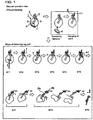
- a pig leg part consists of an ankle, lower femur bones 2, a femur bone 3, a hipbone 4, a knee cap 6 located at the front part of the knee joint part 5, and meat 7 surrounding these bones.
- the hipbone 4 is removed manually in a preprocessing step.
- the pig leg part 1 got rid of the hipbone is fitted at its ankle 8 by a worker to a clamper 11 which is transferred by a transfer chain 12 shown in FIG2 in horizontal direction at a constant speed without discriminating whether the pig leg part 1 (hereafter referred to as work 1) is a right or left thigh.
- the pig leg part 1 is processed automatically at the first step ST1 through the ninth step ST9 as shown in FIG.1 in a state the work 1 is hanged from the clamper 1.
- the work 1 is hanged in a state its fat layer faces backward(backward means here a direction toward chain wheels 13) from the first step ST1 to the sixth step ST6.
- a plurality of clampers 11 are attached to a transfer chain 12 at an equal spacing and transferred horizontally at a constant transfer speed along a transfer route of the chain in a state the work 1 is hanging from the clamper 11.
- the transfer chain 12 is looped over a pair of chain wheels 13(one of the wheels is not shown in the drawing) to form a circulation route.
- the clamper 11 attached to the chain swingable along the transfer direction and a rotation mechanism for rotating the clamper 11 is provided.
- the work 1 can be rotated by the rotation mechanism so that the clamper 11 is rotated based on the discrimination result whether the work 1 is right thigh or left thigh discriminated at the first step ST1 as mentioned later.
- the clamper attached to the chain 12 swingable on a swing axis 11a(see FiGS. 13 and 14 ) so that it can slant when meat is scraped off from the lower femur bones and the femur bone while transferring the clamper.
- incision making steps of ST3-ST5 are installed three robot arms 30, 40, and 50 each for each of the steps.
- a transfer chain 14 is looped over a pair of chain wheels 13 located between the beginning side of ST3 and end side of ST5.
- a plurality of backside stabilizers 15 are attached to the transfer chain 14 at a constant spacing the same to that of the clampers 11.
- the backside stabilizer 15 serves to support the work 1 hanging from the clamper 1 from the backside.
- a stabilizing guide bar 16 which supports the part of the work 1 where the hipbone is removed from the front side of the work 1.
- a safety railing 17 is provided to surround processing devices in the steps ST3-ST6.
- the work 1 is supported by 3-point supporting by the clamper 11, backside stabilizer 15, and stabilizing guide bar 16 in the incision making steps ST3 ⁇ ST6 so that incision is made to the work 1 in a state the work 1 does not swing.
- the work 1 (a pig leg with the hipbone 4 removed) is transferred by the clamper 11 in a direction shown by an arrow a after it is preprocessed to remove the hipbone.
- a right thigh is referred to as work 1l and left thigh as work 1 (L).
- work 1l a right thigh
- work 1 (L) left thigh
- FIGS.3a and 3b when the work 1 hanging from the clamper 11 with its fat layer directed backward in ST 1, the femoral head 3a comes to the right side when the work 1 is a right thigh, and the femoral head 3a comes to the left side when the work 1 is a left thigh. This is utilized for the discrimination of right or left of the pig leg part 1.
- a lifter plate 24 and a sensing plate 21 supported wingable by the lifter plate 24 are provided below the work 1 so that the swing center P of the sensing plate 21 is on the vertical center line C of the work 1.
- the lifter plate 24 is connected to a piston rod 26 of an air cylinder 25.
- a left proximity sensor 23 and right proximity sensor 22 are attached to left end part and right end part of the lifter plate 24 respectively.
- the sensing plate 21 Is lifted up by the air cylinder 25 from below the femoral head 3a in direction of arrow e.
- the sensing plate 21 contacts the femoral head 3a, the sensing plate 21 inclines such that contacted side of the sensing plate 21 moves downward and comes close to the proximity sensor 22 or 23.
- the proximity sensor 22 or 23 detects direction of inclination of the sensing plate 21. Discrimination of whether the work 1 is a left thigh or right thigh is done according to direction of inclination of the sensor plate 21.
- length of work 1 is obtained by measuring lifted distance A of the sensing plate 21 when it has contacted the femoral head 3a, and subtracting the height A from a distance B which is the distance from the undersurface of the clamper 11 to the sensing plate 21 before it is lifted.
- Result of discrimination of right or left of the pig leg part 1 is used for the selection of cutting operation program in which incision trajectory and rotation direction of the clamper are defined so that the cutter Is manipulated under the selected program in the automatic incision making steps ST3 to ST5, for the selection of a cutter used to make incision along side surfaces of bones in ST6, and for the selection of a meat scraper for right leg or left leg in meat scraping from the lower femur bone in ST7.
- result of measurement of work length is used for the changing-over of cutting operation program in automatic incision making steps ST3 ⁇ ST5, for the estimation of starting point and ending point of cutting along the surface of the bones in ST6, and for the estimation of starting point and ending point of meat scraping along the femur bone in ST7.
- the work 1 is transferred to ST2, meat is cut all around the ankle part(a part of the lower femur bones just below the clamper 11 as shown by a line c in FIG.1 ) with a set of round blade cutters 28 to make meatscraping possible in the post processing.
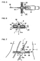
- FIGS.4 to 6 A cutter mechanism as shown in FIGS.4 to 6 is used for the incision making.
- the cutter mechanism is composed such that a cutting tool 33 is mounted to a 6-axis vertical multi-joint robot 30 at an end part 31 a of a robot arm 31 of the robot 30. Incision Is made with this tool from the upper part of the knee joint part 5 to the end of the femur bone 3 as shown by line e in FIG.1 .
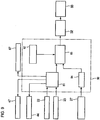
- the cutting tool 33 is manipulated so that the leading end of a cutter reaches the surface of the femur bone and then runs along the surface, while the middle part of the cutter runs along the membrane between the inner thigh meat 52 and a knuckle meat part 51 (shintama in Japanese) as shown by a line e in FIG.8I . If the cutter cuts into meat too deep from the surface of the thigh meat, the meat is damaged. Control of movement of the cutting tool to make incision in the succeeding incision making along incision lines including the line e is performed by a controller 80 shown in FIG.9 . In FIG9 , six cutting operation programs 82 are provided to comply with a right or left of the leg part, large, middle, or small in length of the leg part.
- a right/left leg discrimination means 81 determines whether the pig leg part to be de-boned is a right leg or left leg.
- Lifted distance A detected by a lift height detecting means 27 is inputted to a computing means 104, and the computing means 84 calculates work length W by subtracting the detected distance A from a distance B between the under surface of the clamper 11 and the position of the sensor plate before is lifted up.
- a cutting operation program which can correspond most appropriately with the work 1 to be de-boned is selected from among the plural programs 82 by a selecting means 83.
- a cutter tool 33 is operated under the selected program by means of a cutting tool drive device 32 mounted to the robot 30. In this way, incision making is performed in three steps in ST3-5.
- the cutting tool 33 comprises a base member 36, a swing shaft 34 supported ⁇ wingable by the base member, and a knife-shaped cutter 35 which is attached to the swing shaft 34 to be offset in the direction opposite to the cutter travel direction f
- the cutter 35 has a sharp edged V-shaped cutting edge so that cutting by both sides of the cutter is possible, that means that both sides of the cutter can be permitted to contact the bone when traveling along the surface of the bone without biting into the bone.
- the swing shaft 34 By positioning the swing shaft 34, by which cutting angle g1 is adjusted, nearer to the robot arm 31 than the cutter 35, the point of application force to drive the cutter is advanced toward cutter travel direction f than the actual contact position of the cutter 35 to the bone and meat, so the cutter 35 can be moved along the surface of the bone.
- the swing shaft supporter 36 for supporting the swing shaft43 to which the cutter 35 is attached is slidable by means of a mechanism 37 in directions perpendicular to the robot arm 31 and travel direction f of the cutter 35.
- the slide mechanism 37 comprises a base plate 38 fixed to the robotarm 31 at its end part 31 a to extend in direction perpendicular to the robot arm 31 and travel direction f of the cutter 35, a linear guide rail 39 mounted on the base plate 38 along its longitudinal direction, and a linear guide bar 41 supported by the base member 38 above the linear guide rail 39.
- the linear guide bar 41 penetrates the swing shaft supporter 36 to guide it.
- Coil springs 42 are provided to both sides of the swing shaft supporter to surround the linear guide 41.
- the swing shaft supporter 36 is positioned at the central part of the linear guide bar urged by the springs from both sides when any force does not exerts to slide the swing shaft supporter 36.
- the cutter 35 is slidable in directions perpendicular to the robot arm 31 and travel direction f of the cutter 35 as shown by arrows d in FIG6 and Dwing-able about the swing shaft 43 perpendicular to the slide direction of the swing shaft supporter 34 so that cutting angle g1 is adjustable by the swing of the cutter. Therefore, the cutter 35 can follow the bones in the meat flexibly changing its attitude according to the profile, thickness, and length of the bones.
- a position of the cutter 35 when it contacts the surface of the bone r of the work 1 is set as an initial position of the cutter 35 in the cutting operation program, so the cutter 35 is inserted into the meat until it contacts the bone r as shown in FIG.7 .
- the cutter 35 receives reaction force from the surface of the bone and swings on the center axis of the swing arm 34, and the cutting angle of the cutter 35 is adjusted to g1 so that the cutter 35 directs along the surface of the bone r while moving along the surface of the bone r.
- the cutter 35 can swing on the center axis of the swing shaft 34, which is positioned nearer to the end part 31 a of the robot arm 31 than the cutter 35, by reaction force exerting to the cutter 35 from the bone r, while moving along the surface of the bone with the error due to individual difference of the work 1 being compensated by means of the slide mechanism 37.
- the cutter 35 moves along the surface of the bone r without biting Into the bone nor departing from the surface of the bone. Accordingly, incision can be made smoothly along the surface of the bone r in longitudinal direction thereof, and as the cutter can run accurately along the boundary between the bone r and meat s, the meat adhering on the bone can be cut with increased yield of meat.
- the work 1 is rotated by about 45° in clockwise direction when the work 1 is a right leg part and by about 45° in counterclockwise direction when the work 1 is a left leg by actuating a clamper drive device 44 based on the result of discrimination by the right/left leg discrimination means 81.
- a stabilizing means for stabilizing the work 1 when making incision in ST3 to ST5 will be explained with reference to FIGS.10 and 11 .
- a backside stabilizer 15 supports the surface of the fat layer of the work 1 from backward
- a guide bar 16 supports a part of the work 1 where the hipbone 4 is removed.
- the backside stabilizer 15 is formed such that it has crooked parts 15a at both sides thereof to form a concaved part facing toward the work 1.
- the backside stabilizer 15 is transferred at the same speed as the work 1 and functions to support the surface of the fat layer, to define a back side reference face, and to prevent swinging of the work 1 in the transfer direction a.
- the work 1 is supported at three points, i.e. at an upper part, middle part, and lower part, the work 1 can be transferred without swinging in any direction, and incision can be made at required positions accurately at ST.3 to ST.5.
- incision is made from the upper part of the lower femur bone 2 to the lower side of the knee joint 5.
- a cutter tool manipulated by the multi-joint robot 40 is composed similar to that used in ST3.
- the line of incision made here is shown by h in FIG.8b .
- the cutter is inserted from the upper part of the lower femur bones 2 into a part of meat 54 (chimaki in Japanese), the cutter end further advances passing by the side face of the knee cap 6 to the lower side of the knee joint 5.
- the line of incision made here is shown by I in FIGS.8b and 8c .
- the incision line I in FIG.8c is rotated by about 90° relative to the incision line I in FIG.8b . This is because the lower femur bones 2 are twisted relative to the femur bone 3 and the incision line 58 runs along the bone, so the incision line 58 becomes a twisted line.
- a cutter tool manipulated by the multi-joint robot 40 is composed similar to that used in ST3.
- a multi-joint robot is installed separately for each of the steps ST3 to ST5, it is possible to use one multi-joint robot for making incision of ST3 to ST5 when transfer speed of the work 1 is slow.
- programs as explained in the following are memorized in the controller 80 in order to allow the plurality of multi-joint robots to make the incisions in the steps 3 ⁇ 5 assigning an incision making task to each of the robots.
- a plurality of cutting operation programs 82 are provided in the controller 80 shown in FIG9 . Movement of the cutter 35 of the cutting tool 33 is programmed in each of the programs correspond to left, right, and size of the pig thighs 1.
- Each of the robots is specified to make a specified incision among a plurality of the incisions, and each of the programs is specified to be used to control the cutting tool drive device (incision making device) 32 of the specified robot.
- a program appropriate for the specified incision of a discriminated pig thigh 1 is selected by the selecting means 83 in the controller 80, and control signal for controlling the cutting tool drive device 32 is sent to the specified robot. In this way, incision making operation of a plurality of the incisions is performed by a plurality of the multi-joint robots.
- three routes of incisions are to be performed in the work 1.
- the first robot 30 is specified to perform the incision from the upper part of the knee joint 5 to the lower end of the femur bone 3 as shown in FIG.8c with the line e
- the second robot 40 is specified to perform the incision from the upper part of the lower femur bones 2 to the lower part of the knee joint 5 as shown in FIG.8b and c with the line h
- the third robot 50 is specified to perform the incisions which are made by allowing the cutter 35 to cut into the calf meat part 54 from the upper part of the lower femur bones 2, the end of the cutter to advance passing the side face of the knee cap 6 until it reaches the lower end of the knee joint 5 as shown in FIG.8b and c with the lines I(incisions in calf meat part).
- the cutting operation programs 82 in the controller 80 include programs each of which is used corresponding left, right, and size, and routes of incisions (3 routes in the example).
- an appropriate program is selected by the program selecting means 83 in accordance with left, right the pig thigh, and position of incision specified to be performed by the robot 30, and control signal for controlling the cutting tool 33 of the robot 30 is sent to the cutting tool drive device 32 of the robot 30.
- control signal for controlling the cutting tool 33 of the robot 40 or 50 is sent to the cutting tool drive device 32 of the robot 40 or 50.
- a round blade cutter 46 at ST6 This incision is indicated by a line j in FIG 1 and FIG.8c .
- the incision is made by a round blade cutter 46a for right thigh or round blade cutter 46b for left thigh.
- the cutters 46a and 46b are located to face each other with the clamper transfer chain 12 passing between them as shown in FIG2 .
- the cutter 46a or 46b is selected by actuating a cutter changeover device 47 based on the result of discrimination of right or left of the thigh by the discrimination device 81 as shown in FIG9 .
- the result of discrimination by the right/left thigh discrimination means 81 is sent to the scraper changeover drive device 67.
- the work 1 is a right thigh 1(R)
- the work 1(R) is posed by the scraper changeover device 67 so that the front side of the work 1(R) to face the round blade cutter 40a, and incision is made by the round blade cutter 40a.
- the work 1 (L) is a left thigh 1(R)
- the work 1(L) is posed by the scraper changeover device 67 so that the front side of the work 1(L) to face the round blade cutter 40b, and incision is made by the round blade cutter 40b.
- the work 1 is transferred in an attitude that the knee cap 6 thereof is directed toward upstream of the work transfer direction 'a' in steps ST6 to ST8, irrelevant to whether the work 1 is a right or left leg part.
- steps ST6 to ST8 irrelevant to whether the work 1 is a right or left leg part.
- meat scraping from the lower femur bones is carried out in ST7.
- This meat scraping is performed using a lower thigh scraping device 60 shown in FIGS. 12 and 13a ⁇ c .
- the lower femur bones consist of a shinbone 2a and a fibula 2b as shown in FIG.12 .
- the scraping device 60 is composed to meat the configuration of the lower femur bones 2.
- the lower thigh scraping device 60 comprises a scraper plate 61, a base plate 66 onto which the scraper plate 61 is attached, an air cylinder 63, and a swing scraper plate 62.
- the base plate 66 is connected to a piston rod 64 of the air cylinder 63.
- the swing scraper plate 62 is urged by a spring not shown in the drawing to be swingable on a swing axis 62a fixed to the scraper plate 61.
- a pair of guide rods 65 is to guide up and down movement of the scraper plate 61 in directions shown by an arrow k.
- the swing scraper plate 62 is to guide up and down movement of the scraper plate 61 in directions shown by an arrow k.
- the scraper plate 61 has an inserting protrusion part 61 a which can intrude into the gap between the shinbone 2a and fibula 2b.
- the lower femur bones 2 are surrounded by the shank 55 and a meat part 54 (chimaki in Japanese) adhering to the bones. It is necessary to use scraper plates of different shape separately for a right leg part and left leg part, for relative position of the shinbone and fibula differs depending on whether it is right leg or left leg.
- a right lower thigh scraping device 60a is provided with a right thigh scraper plate and a left lower thigh scraping device 60b provided with a left thigh scraper plate are located to face each other with the clamper transfer chain 12 passing between them as shown in FIG.2 .
- the work 1 is already posed concerning its rotation position in ST6 based on the result of discrimination at ST1 whether the work 1 is right leg or left leg such that the backside of a right leg part faces toward the right lower thigh scraping device 60a and the backside of the left leg faces toward the left lower thigh scraping device 60b, so meat scraping of the right leg is carried out by the right lower thigh scraping device 60a and scraping of the left leg is carried out by the left lower thigh scraping device 60b.
- the lower thigh scraping device 60 shown in FIG 12 is a right lower thigh scraping device 60a.
- the air cylinder 63 is actuated to push the scraper plate 61 toward the work 1(R) at the timing right before the work 1(R) comes in front of the scraper plate 61.
- the inserting protrusion part 61a of the scraper plate 61 intrudes into the gap between the shinbone 2a and fibula 2b of the work 1(R), at the same time the swing scraper plate 62 contacts the calf meat part 54 to be swung upward, and the leading end of the swing scraper plate 62a comes close to the surface of the shinbone.
- the scraper plate 61 comes on the shank 55 and the swing scraper plate 62 comes on the calf meat 54.
- the work 1(R) is further transferred horizontally in direction of arrow a, the work 1(R) is slanted with its lower femur bones 2 held by the scraper plate 61 and swing scraper plate 62 as shown in FIGS.13a and 13b .
- the clamper 11 is attached to the swing chain 12 via the swing axis 11a, the work 1(R) is slanted easily, and the lower femur bones 2 are raised obliquely upward in relation to the clamper plates 61.
- the inserting protrusion part 61 a of the scraper plate 61 is inserted in between the fibula 2b and shinbone 2a, the fibula 2b is pressed to the scraper plate 61 strongly as the ankle of the work 1® is pulled by the clamper 11 in a state the shank and calf meat 54 are held down by the scraper plate 61 and swing scraper plate 62, so meat between the fibula and shinbone can be scraped off Further, by forming the end part of the inserting protrusion part 61 a of the scraper plate 61 to be sharp like a cutter, effect of scraping the meat between the fibula and shinbone can be further increased.
- the work 1 (R) with meat around the lower femur bones scraped is transferred to ST8 in an attitude the knee cap is directed toward upstream of the transfer direction.
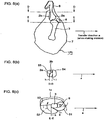
- a meat scraper plate 71 located at a height position where the joint part 5 of the work 1 (R) is in the transfer route, the meat scraper plate 71 being inclined downward to the transfer direction a.
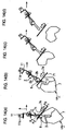
- the meat scraper plate 71 has a recess 72 as shown in FIG 16 .
- the recess 72 is open toward upstream of the transfer direction a(the opening being indicated by reference numeral 72a), the width of the opening 72a being such that the joint part 5 can intrudes into the recess 72, and the bottom of the recess 72 is formed in a V-shape in order to bring the femur bone toward central part so that the femoral head does not interfere with the edge of the recess 72 when scraping meat.
- a pair of round blade cutters 74 as shown in FIG.15 is provided right above the meat scraper 71 parallel thereto.
- the pair of cutters 74 serves to make incision around the femur bone 3 at middle parts between the part just above the knee cap 5 and the femoral head and make final cutting below the femoral head to separate the meat finally.
- the position of the final cutting is determined by detecting the position of the knee joint 5.
- each of the cutters is moved toward the right and left direction respectively in relation to the transfer direction a and also moved in the direction opposite to the transfer direction as shown by an arrow m.
- a pair of swing plates 75 is attached to the meat scraper 71 to close the opening 72a of the concave portion 72 in order to prevent the femur bone intruded into the recess 72 of the meat scraper 71 from being disengaged.
- Each of the swing plates 75 supported by the meat scraper plate 71 swingable in directions shown by an arrow n about a swing center 75a by moving a piston rod 76a of an air cylinder 76 in direction shown by an arrow q, thereby opening up or closing down the opening 72a of the recess 72.
- the knee joint part 5 of the work 1 (R) transferred in the direction a to ST8 comes into the recess 72 of the meat scraper plate 71 provided at the height position of the knee joint 5.
- the air cylinder is actuated to swing the pair of swing plates 75 to close the opening 72a of the meat scraper plate 71, thus the joint side end part of the femur bone of the work 1 (R)is chucked by the meat scraper plate 71.
- the clamper 11 continues to move horizontally in the direction a, the meat part of the work 1(R) is pushed obliquely upwardly by the undersurface of the meat scraper plate 71 which is fixed in position and the femur bone 3 is strongly pressed to the V-shaped bottom 73 of the recess 72 of the meat scraper plate 71 by force due to the weight of the work 1(R).
- meat scraping can be performed with increased yield of meat, by making two incisions around the bone between the part just below the knee joint part and the femoral head and cutting biological tissue such as meat, tendon, ligament, etc. adhering to the bone.
- meat scraping process is simplified dramatically, process time Is shortened, and processing capacity is increased. Further, a number of sets of combination of a meat scraper, cutter, and work lifting device are needed to compose a conventional de-boning apparatus, whereas according to the embodiment, meat scraping similar to the conventional meat scraping can be carried out by providing only one set of combination of a meat scraper and cutter, and a work transfer device-Therefore, substantial cost reduction and space-saving are attained.
- the bones separated from the meat part 7 and remaining in a state clamped with the clamper 11 in ST8 is released from the clamper 11 by means of a bone discharging means not shown in the drawings falls down to be discharged form the apparatus.
- FIG 17 is a plan view showing overall configuration of the apparatus of the second embodiment
- a pig leg part 1 with the hipbone not removed is transferred on a belt conveyor 101 to ST1.
- Each worker w shifts the pig leg part 1 onto a cutting board 102 and removes the hipbone 4 on the cutting board 102 as a preprocessing. Then the worker w inserts the ankle part of the pig leg part 1 with the hipbone 4 removed into a gap between two work hanger tables 103 arranged parallel to each other.
- the work 1 hanged between the gap formed by the two work hanger tables 103 is pushed intermittently toward a discrimination device 110 for discriminating whether the pig leg is a right leg or left leg by a pusher actuated by an air cylinder not shown in the drawing.
- a discrimination device 110 for discriminating whether the pig leg is a right leg or left leg by a pusher actuated by an air cylinder not shown in the drawing.
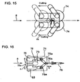
- FIG 18 shows the state the discrimination device 110 is applied to discriminate right or left of a pig leg part
- FIG 19 is a section along line I-I on FIG.18
- FIG20 shows drive mechanism of a pair of measuring arms of a pair of measuring arms 111(112) of the discrimination device 110.
- the two work hanger tables 103 are located so that the gap between the two work hanger tables 103 is perpendicular to a transfer chain 12 moving in a horizontal plane.
- the ankle part of the pig leg part 1 is inserted into the gap between the work hanger tables 103 so that the fat layer 1 a is directed toward the transfer chain 12 by the worker. Then the pig leg part is pushed toward the discrimination device 110 in a hanged attitude as mentioned above.
- the pairs of measuring arms 111 and 112 approach a pig leg part 1 with hipbone removed(work 1) from either side of the work 1 to pinch the work 1.
- the pair of measuring arms 111 and 112 stops when they have pinched the work 1.
- Mechanism for driving the measuring arms will be explained referring to FIG20 .
- the pair of measuring arms 111 (112) has a rack 113(114) extending horizontally (perpendicular to the pair of arms 111(112)) fixed to the arms.
- Each of the racks 113,114 engages with a pinion 115 located between the racks.
- a piston rod 117 connected to a piston 116a of an air cylinder 116 is connected to one of the measuring arms of the pair of measuring arms 111 (112).
- Distance ⁇ (or ⁇ ) between the arms of the air of arms 111 (112) can be adjusted by actuating the air cylinder 116.
- An encoder 118 is connected to the pinion 115. The distance ⁇ (or ⁇ ) is detected by detecting rotation angles or counting the number of rotation of the encoder 118 by means of a judging means 119 forjudging right or left of a thigh.
- the pair of measuring arms 111(112) stops automaticallywhen it clamps the work 1 and receives reaction force of certain largeness from the work 1.
- measured distance ⁇ and p are compared. For example, it is judged that, when ⁇ , the work 1 is a right thigh, and when ⁇ , the work 1 is a left thigh.
- the measurement is carried out by pinching the work 1 with two pairs of measuring arms when the work 1 transferred intermittently to a position in front of the discrimination device 110 is stopped there, discrimination of a right thigh from a left thigh can be done accurately with the discrimination device of simple construction.
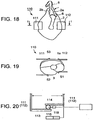
- a work shifting device 120 will be explained referring to FIG.21 .
- the work 1 hanging in the gap between the work hanger tables 103 is pushed by an air cylinder 121 to a work shift guide 122 located between the work hanger tables 103 and transfer chain 12.
- the work shift guide 122 has a pair of clamper plates between which the ankle part of work 1 is inserted pushed by the air cylinder 121.
- the work shift guide 122 can be moved in the same direction and at the same speed in synchronism with the clamper 11 by a drive means not shown in the drawing.
- the work 1 is shifted to the clamper 11 pushed by an air cylinder 123 toward the clamper 11 while the work shift guide 122 is moving in synchronism with the clamper 11. After the work 1 is shifted to the clamper 11, the work shift guide 122 is returned to the original position said drive means.
- the clamper 11 attached to the transfer chain 12 driven by a transfer chain drive device 113(see FIG. 17 ) is moving at a constant speed, and the work 1 shifted to the clamper 11 reaches in front of a work length detecting means 130.
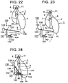
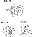
- processing devices of ST2 to ST8 are surrounded by a safety railing 114 as shown in FIG 17 . Construction of the work length detecting means will be explained referring to FIGS.22 to 25 .
- reference numeral 130 is a work length detecting means.
- a detecting arm 132 is supported swingablly at an end thereof by a bracket fixed to a base bracket 131.
- a limit switch or proximity switch 134 (hereafter referred to as a switch 134) is fixed to a horizontal plate of the base bracket 131 below the other end of the detecting arm 132. Lifted distance of the base bracket 131 when the switch 134 has detected that the other end of the detecting arm 132 has come close to or contacted the switch 134, is measured.
- a support shaft 136 is provided to an upper end part of a support pillar 135 of the base bracket 131, and a pusher arm 137 is supported swingablly via the support shaft 136.
- a round bar 138 is attached to the pusher arm 137 to the pusher arm 137 to the pusher arm 137 to the pusher arm 137 to the detecting arm upward so that the end of the detecting arm 132 is kept apart from the switch 134 unless force exerts to push down the detecting arm 132.
- the round bar 138 attached to the pusher arm 137 is a long bar, so the pusher arm 137 can be rotated in clockwise direction smoothly without the round bar 138 interrupted by the work 1.
- the lower part thereof is scooped out deeply and femoral head 3a is exposed.
- the femoral head 3a is not so apart from the lower end part 1b of the work 1, so when the detecting arm 132 comes near to the work 1, the end of the detecting arm 132 may interfere with the lower end part 1b of the work 1.
- the work length detecting means 130 composed like this, first the base bracket 131 is advanced in direction of arrow u into position, then lifted up in direction of arrowv.
- the detecting arm 132 comes to contact with the femoral head 3a of the pig leg part 1 after the pusher arm 137 comes to contact with the lower end part 1 b of the pig leg part 1 and pushes it away, so the detecting arm 132 can come to contact with the femoral head 3a without interfered by the thigh meat. Therefore, work length W can be measured accurately
- the work length detecting means 130 is transferred at the same speed as the work transfer speed during the measurement When the measurement is finished, the work length detecting means 130 is returned to the initial position.
- Incision making processes in ST3 to ST6 are done in the same way as done in the first embodiment.
- work stabilizing mechanism when performing incision making processes In ST3 to ST5 using robot arms 30 to 50 is different from that of FIGS.10 and 11 of the first embodiment. Work stabilizing mechanism of the second embodiment will be explained with reference to FIGS.17 , 26, and 27 .
- the stabilizing mechanism of the embodiment adopt a backside supporting mechanism 150 to support the work 1 from the backside(fat layer 1a side) of the work 1.
- the backside supporting mechanism 150 is composed of a base support member 151 which is disposed to face the backside of the work and slanting from vertical direction, pairs of arms 152 of which the arms of each pair extend from the base support member 151 toward both sides and slanted forwardly so that the support arms 152 can contact the backside surface of the work 1, and a support shaft 153 for supporting the base support member 151.
- the work 1 is supported by the supporting mechanism in a state it is slanted forwanity, that is, the work hanging from the clamping device is slanted pushed forward by the arms 152 as shown in FIG.27 . Therefore, a part of the weight of the work 1 is supported by the supporting mechanism, so the work 1 is not swung by the force applied by the cutter manipulated by the robot 30, 40, or 50 when incision is made to the work, that is, the work 1 is stabilized against the cutting force of the cutter. Further, incision making is facilitated by slanting the work 1.
- the guide bar 35 provided in the front side of the work 1 in the case of the first embodiment shown in FIGS.10 and 11 is not provided.
- the work 1 As the work 1 is supported in an attitude slanted forwardly as shown in FIG27 , the work 1 can be stabilized when making incision to the work 1 without the guide bar 16.
- the guide bar 16 As the guide bar 16 is not provided, it is possible to accommodate the work 1 of various lengths.
- the base support member 151 of the backside stabilizing mechanism 150 Is attached to a block via the support shaft 153.
- the block 154 is engaged with a timing belt 157 and can be moved in the transfer direction a in synchronism with the transfer of the clamper 11 bydriving(rotating) the endless belt 157 by means of a servo motor 158.
- the block 154 is also engaged with a linear guide155 slidably so that the block can be moved smoothly without rattled by the force acting from the robot arm.
- the supporting mechanism 150 When making incision, the supporting mechanism 150 is moved in the transfer direction a at a speed the same as the clamper 31 in synchronism with the clamper 11 and supports the work 1 on the backside thereof.
- the backside stabilizing mechanism 150 is departed backward from the transfer route of the clamper 11 by actuating an air cylinder 156 attached to the block 154. Then the block 154 is moved in the direction opposite to the transfer direction a to be returned to the initial position. The block 154 is again advanced to the transfer route of the clamper 11 and support the next work 1 from the backside thereof.
- backside stabilizing mechanism 150 With the backside stabilizing mechanism 150 of this construction, control of transfer speed of the mechanism 150 is possible by the servo motor 148, so the mechanism 150 can accommodate an arbitrary transfer speed of the work. Further, installation space is reduced as compared with the backside stabilizer 33 transferred by the chain 34 as shown in FIG.7 . Furthermore, when the backside stabilizing mechanism 150 is returned to the initial position, it is returned at a speed of 2 or 3 times the transfer speed of the work, so it can accommodate speeding up of work transfer.
- FIGS.28 to 30 Lower thigh scraping process at ST7 in the second embodiment will be explained referring to FIGS.28 to 30 .
- the explanation will be done in the case of a right leg part, i.e. work 1(R).
- the inserting protrusion part 61 a to be inserted in between the shinbone 2a and fibula 2b is formed integral with the scraper plate 61 of the right lower thigh scraping device 60a in first embodiment as shown in FIG 12
- a separate plate member 161a is provided instead of the inserting protrusion part 61a in the first embodiment, and a scraping plate 161 of the right lower thigh scraping device 160a has no inserting protrusion part to be Inserting in between the shinbone 2a and fibula 2b as shown in FIG29 .
- the plate member 161a having an inserting protrusion part at its end is moved across the transfer line 12 from the opposite side of the scraping device 160a, and the inserting protrusion part of the plate member 161a intrudes into the gap between the of the shinbone 2a and fibula 2b of the transferring work 1(R).
- the scalper plate 161 and a swing scraper plate 162 are moved toward the transfer line 12 to contact to the bones of the work 1(R) as shown in FIG29 .
- meat around the lower femur bones is scraped off by the plate member 161 a, scraper plate 161, and swing scraper plate 162.
- the swing scraper plate 62 is swingable on a swing axis 162a, and urged by an elastic force downward swing direction.
- the plate member 161 a having an inserting protrusion part to be inserting in between the shinbone 2a and fibula 2b is provided separately from the scraper plate 161, so the inserting protrusion part of the plate member 161a can be brought into contact with the rear surface of the shinbone 2a(portion x in FIG 29 ) without fail. Therefore, meat near here can be positively scraped.
- the scraper plate 161 can be brought into contact with the outer surface of the fibula 2b(portion y in FIG30 ) without fail, so meat near here can be positively scraped. As a result, yield of meat is increased.
- discrimination of the work 1 whether it is a right thigh or left thigh is done by the discrimination device 110 In ST1 In a state the work 1 is not transferring, the discrimination can be done accurately without fail. In the succeeding steps, processing is done while transferring the work 1 continuously at a constant speed, and the backside stabilizing mechanism 150 is adopted which can accommodate speed up of work transfer, so, processing capacity of 500 thighs/hr, for example, can be attained. Further, as work length detecting means which can detect the length of the work accurately and efficient thigh meat scraping devices are adopted, yield of meat can be increased.
- automation level of de-boning operation of an arm or leg part of a slaughtered domestic animal is increased by automating incision making which has been not automated in the past because of its difficulty, and de-boning process is dramatically simplified.
- processing time is shortened and process efficiency is largely increased.
Landscapes
- Life Sciences & Earth Sciences (AREA)
- Engineering & Computer Science (AREA)
- Food Science & Technology (AREA)
- Wood Science & Technology (AREA)
- Zoology (AREA)
- Processing Of Meat And Fish (AREA)
- Folding Of Thin Sheet-Like Materials, Special Discharging Devices, And Others (AREA)
Claims (14)
- Procédé pour désosser une pièce (1) étant une partie de jambe de derrière d'un porc abattu, son os iliaque (4) enlevé, le procédé comprenant :un processus d'incision (ST3, ST4, ST5) pour faire une incision le long des os de la pièce (1), y compris une partie d'articulation du genou (5), dans la direction longitudinale des os pendant que la pièce (1) est transférée dans un état suspendu à un dispositif de serrage avec sa cheville (8) étant serrée par le dispositif de serrage,un processus de positionnement pour positionner la partie de cheville de la pièce (1) en cours de transfert avec la cheville (8) étant serrée par le dispositif de serrage en permettant à une partie de la partie de cheville juste au-dessous du dispositif de serrage de s'introduire dans une partie concave (72) d'une plaque de racloir (61, 71, 161) située en aval de la pièce (1) en cours de transfert de telle façon qu'elle soit inclinée vers le bas vers la direction de transfert (a) du dispositif de serrage, la partie concave (72) étant formée de telle façon que les os de la pièce (1) puissent la traverser, etun processus de raclage de viande pour racler la viande entourant les os en transférant le dispositif de serrage, dans lequel la viande est retenue par la plaque de racloir (61, 71, 161) et reçoit une force de raclage inclinée vers le bas vers l'amont de la direction de transfert (a) par la plaque de racloir (61, 71, 161), la viande étant ainsi raclée des os pendant que le dispositif de serrage est transféré,caractérisé en ce qu'un processus de discrimination est effectué utilisant un moyen de discrimination (81, 110) afin de discriminer si la pièce (1) est une pièce droite ou gauche,un processus de détection de longueur est effectué utilisant un moyen de détection de longueur de pièce (130) afin de détecter la longueur de la pièce (1), etle processus d'incision (ST3, ST4, ST5) comprendcontrôler le mouvement d'un couteau (35) d'un outil de coupe (33) étant attachée à une partie d'extrémité (31a) d'un bras robotique (31) d'un robot (30) multiarticulé à six axes en sélectionnant un programme d'opération approprié d'une pluralité de programmes d'opération (82) étant prévus dans un contrôleur (80) par un moyen de sélection de programme (83) sur la base du résultat de détection de la pièce gauche ou droite et de la longueur de la pièce (1) et transmettre un signal de contrôle sur la base du programme d'opération sélectionné à partir du contrôleur (80) au robot (30) multiarticulé à six axes, chacun de la pluralité de programmes d'opération (82) définissant le mouvement du couteau (35) de sorte qu'il correspond à la pièce droite ou gauche et à la longueur de la pièce (1).
- Procédé pour désosser une partie de jambe d'un porc avec sa hanche enlevée selon la revendication 1, dans lequel le procédé comprend :un processus d'incision pour faire une incision dans la partie de viande de la jambe de porc le long les os de la jambe inférieure (2) et le fémur (3) de la partie de jambe de porc dans la direction longitudinale des os pendant que la partie de jambe de porc est transférée dans un état suspendu au dispositif de serrage avec sa cheville (8) serrée par le dispositif de serrage,un premier processus de positionnement pour positionner la partie de cheville de la partie de jambe de porc en cours de transfert avec la cheville (8) serrée par le dispositif de serrage en permettant à une partie de la partie de cheville juste au-dessous du dispositif de serrage à percuter contre une première plaque de racloir située en aval de la partie de jambe de porc en cours de transfert de telle façon qu'une partie saillante d'insertion (61a) de la première plaque de racloir es insérée entre un tibia (2a) et une fibule (2b) composant les os de la jambe inférieure (2), par quoi la viande de jarret peut se positionner juste au-dessous de la première plaque de racloir (61) et la viande de mollet est retenue par une plaque de racloir pivotante (62) attachée d'une manière pivotante à la plaque de racloir,un premier processus de raclage de viande pour racler la viande entourant les os de la jambe inférieure (2) en transférant le dispositif de serrage dans un état dans lequel la viande entourant les os de la jambe inférieure (2) est retenue par la première plaque de racloir principale et la plaque de racloir pivotante (62), par quoi la viande reçoit une force de raclage inclinée vers le bas vers l'amont de la direction de transfert (a) par la première plaque de racloir principale et la plaque de racloir pivotante (62) afin d'être raclée des os de la jambe inférieure (2) pendant que le dispositif de serrage est transféré,un deuxième processus de positionnement pour positionner la jambe de porc avec la viande raclée des os de la jambe inférieure (2) restant en transférant la partie de jambe de porc dans un état suspendu au dispositif de serrage et en permettant à l'articulation du genou (5) parmi la partie de jambe de porc à s'introduire dans une partie concave d'une deuxième plaque de racloir inclinée vers le bas vers l'aval de la direction de transfert (a), la partie concave étant ouverte vers l'amont de la direction de transfert et étant formée de telle façon que l'articulation du genou (5) et le fémur (3) puissent la traverser,un deuxième processus de racloir de viande pour racler la viande entourant le fémur (3) en transférant le dispositif de serrage dans un état dans lequel la viande est retenue par la deuxième plaque de racloir, par quoi la viande reçoit une force de raclage inclinée vers le bas vers l'amont de la direction de transfert (a) par la deuxième plaque de racloir afin d'être raclée du fémur (3) pendant que le dispositif de serrage est transféré plus loin, etun processus de séparation final pour séparer la viande de la tête fémorale (3a) du fémur (3).
- Procédé de désossement selon la revendication 2, dans lequel le processus d'incision comprend :un premier processus d'incision pour faire une incision de telle façon que la pointe du couteau (35) entre dans la viande à partir de la partie supérieure de la partie d'articulation du genou (5) de la jambe de porc et se déplace le long la surface du fémur (3) et la partie centrale du couteau (35) se déplace le long une membrane entre la viande de l'intérieur de la cuisse et la viande de la partie postérieure de la cuisse jusqu'au l'extrémité de la tête fémorale (3a),un deuxième processus d'incision pour faire une incision à partir de la partie supérieure des os de la jambe inférieure le long les os de la jambe inférieure (2) jusqu'à la partie inférieure de l'articulation du genou (5) ; etun troisième processus d'incision pour faire une incision de telle façon que la pointe du couteau (35) entre dans la viande du mollet et se déplace en passant devant la rotule jusqu'au dessous de la partie d'articulation (5) ;permettant ainsi le raclage souple de la viande et prévenant l'obstruction de la viande à la partie de pincement de la plaque de racloir de viande quand la viande est raclée dans un étant dans lequel la rotule est sur le côté en amont du fémur.
- Procédé de désossement selon la revendication 2, dans lequel la partie de jambe de porc est serrée par le dispositif de serrage et y suspendue de telle façon que la couche de graisse (1a) de la partie de jambe de porc soit toujours orientée vers une direction déterminée, une plaque pivotant sur un axe pivotant (62a) est soulevée par en dessous de la partie de jambe de porc suspendue jusqu'à ce que la plaque vienne en contact avec la tête fémorale (3a) de la partie de jambe de porc de telle façon que l'axe pivotant (62a) soit sur une ligne centrale de la jambe de porc suspendue, dans lequel on détecte si la jambe de porc est une jambe droite ou une jambe gauche en détectant une direction d'inclinaison de la plaque au contact avec la tête fémorale (3a) ; et une distance de levage de la plaque est détectée quand la plaque vient en contact avec la tête fémorale (3a) et une longueur de la partie de jambe de porc est calculée sur la base de la distance de levage détectée.
- Procédé de désossement selon la revendication 4, dans lequel une pluralité de programmes (82) est prévue dans chacun desquels un mouvement d'un couteau (35) pour faire une incision est prédéfini afin de correspondre au droit ou à la gauche et à la longueur de la partie de jambe de porc, un programme qui correspond de la manière la plus appropriée à une partie de jambe de porc à traiter étant sélectionné parmi la pluralité de programmes sur la base du résultat de la détection d'une partie droit ou d'une partie gauche et de la longueur de la partie de jambe de porc, et le couteau (35) étant manipulé selon le programme sélectionné.
- Dispositif de désossement pour désosser une pièce (1) étant une partie de jambe de derrière d'un porc abattu, son os iliaque (4) enlevé, comprenant :un dispositif de serrage pour serrer et suspendre la pièce (1),un dispositif de transfert pour transférer horizontalement le dispositif de serrage,un dispositif d'incision (32) pour faire une incision dans la viande le long des surfaces des os de la pièce (1) dans la direction longitudinale des os, etune plaque de racloir (61) qui a une partie concave (72) formée de telle façon que les os de la pièce (1) puissent la traverser et étant située en aval de la partie de jambe de porc en cours de transfert de telle façon qu'elle soit inclinée vers le bas vers la direction de transfert (a) du dispositif de serrage, dans lequel la pièce (1) est transférée dans un état dans lequel une partie de la partie de cheville juste au-dessous du dispositif de serrage s'est introduite dans la partie concave (72) de la plaque de racloir (61), la viande qui adhère aux os étant ainsi retenue par la plaque de racloir et recevant une force de raclage inclinée vers le bas vers l'amont de la direction de transfert (a) par la plaque de racloir (61) afin d'être raclée des os pendant que le dispositif de serrage est transféré,caractérisé en ce qu'un moyen de discrimination (81, 110) est prévu qui est apte à effectuer un processus de discrimination afin de discriminer si la pièce est une pièce droite ou gauche, etle dispositif d'incision (32) comprend une pluralité de robots (30, 40, 50) multiarticulés à six axes, chacun ayant un bras robotique (31) et un outil de coupage (33) comprenant un couteau (35) étant attaché à une partie d'extrémité (31a) du bras robotique (31),et un moyen de détection de longueur de pièce (130) est prévu qui est apte à effectuer une détection de la longueur de la pièce (1),et un contrôleur (80) comprenant un moyen de sélection de programme (83) et une pluralité de programmes d'opération (82) dont chacun définit le mouvement du couteau de sorte qu'il correspond à la pièce droite ou gauche et à la longueur de la pièce (1), dans lequel le contrôleur est connecté à chaque robot (30) multiarticulé à six axes et est opérable à contrôler l'outil de coupage (33) du robot (30, 40, 50) multiarticulé à six axes en sélectionnant un programme d'opération approprié par le moyen de sélection de programme (83) sur la base du résultat de la détection de la pièce droite ou gauche et de la longueur de la pièce (1) et transmettant un signal de contrôle sur la base du programme d'opération sélectionne à partir du contrôleur (80) au robot (30) multiarticulé à six axes.
- Dispositif pour désosser une partie de jambe d'un porc avec sa hanche enlevée selon la revendication 6, dans lequel le dispositif comprend :un moyen de transfert pour transférer des dispositifs de serrage dont chacun serre la partie de jambe de porc à sa cheville (8) pour la suspendre,une pluralité de moyens d'incision pour faire une incision dans la partie de viande de la partie de jambe de porc le long ses os de la jambe inférieure (2) et le fémur (3) dans la direction longitudinale ;un premier moyen de racloir de viande pour racler la viande entourant les os de la jambe inférieure (2) pendant que la partie de jambe de porc est transférée, comprenantun partie saillante d'insertion qui entre dans l'espace entre un tibia et une fibule composant les os de la jambe inférieure (2) quand la partie de jambe de porc en cours de transfert percute contre la partie saillante d'insertion,une première plaque de racloir qui est située en aval de la partie de jambe de porc transférée et retient la viande de jarret quand la partie de jambe de porc vient sous la première plaque de racloir, etune plaque de racloir pivotante (62) qui retient la viande de mollet quand la partie de jambe de porc vient sous lesdites plaques de racloir ;un deuxième moyens de racloir de viande pour racler la viande entourant la fémur (3) pendant que la partie de jambe de porc est transférée plus loin, comprenant une deuxième plaque de racloir qui est située en aval de la partie de jambe de porc transférée dont la viande entourant les os de la jambe inférieure (2) est raclée par les premiers moyens de racloir, la deuxième plaque de racloir étant inclinée vers le bas vers l'aval de la direction de transfert et ayant une partie concave qui est ouverte vers l'amont de la direction de transfert et étant formée de telle façon que l'articulation du genou (5) et le fémur (3) puissent traverser la partie concave, etun dispositif de coupage qui coupe des tissus biologiques autour du fémur (3) dans le processus de raclage de la viande de cuisse du fémur et sépare la viande de la tête fémorale (3a) au fin du raclage de viande ;dans lequel la viande entourant les os de la jambe inférieure (2) est raclée en transférant le dispositif de serrage afin de permettre à la viande de recevoir une force de raclage inclinée vers le bas vers l'amont de la direction de transfert par la première plaque de racloir, la viande entourant le fémur est raclée en transférant plus loin le dispositif de serrage afin de permettre à la viande de recevoir une force de raclage inclinée vers le bas vers l'amont de la direction de transfert par la deuxième plaque de raclage, et la viande raclée des os de la jambe inférieure et du fémur est séparée de la tête fémorale par le couteau.
- Dispositif de désossement selon la revendication 7, dans lequel le moyen d'incision comprend :un premier moyen d'incision pour faire une incision de telle façon que la pointe d'un couteau entre dans la viande à partir de la partie supérieure de la partie d'articulation du genou (5) de la jambe de porc et se déplace le long la surface du fémur (3) et la partie centrale du couteau se déplace le long une membrane entre la viande de l'intérieur de la cuisse et la viande de la partie postérieure de la cuisse jusqu'au l'extrémité du fémur (3) de côté de la tête fémorale (3a),un deuxième moyen d'incision pour faire une incision à partir de la partie supérieure des os de la jambe inférieure (2) le long le fémur jusqu'à la partie inférieure de l'articulation du genou (5) ; etun troisième moyen d'incision pour faire une incision de telle façon que la pointe du couteau entre dans la viande de mollet et se déplace en passant devant la rotule jusqu'au dessous de la partie d'articulation.
- Dispositif de désossement selon la revendication 7, dans lequel le moyen de discrimination (81) pour discriminer si la partie de jambe de porc est une jambe droite ou une jambe gauche et parallèlement pour détecter la longueur de la partie de jambe de porc est prévu en amont du moyen d'incision, le moyen de discrimination (81) ayant une plaque qui peut être pivotée sur un axe de pivotement (62a) et qui pivot quand elle vient en contact avec la tête fémorale (3a) de la partie de jambe de porc suspendu au dispositif de serrage, par quoi la plaque est soulevée vers la partie de jambe de porc par en dessous jusqu'à ce que la plaque vienne en contact avec la tête fémorale (3a) de telle façon que l'axe de pivotement (62a) se déplace sur la ligne centrale verticale de la partie de jambe de porc suspendue, la discrimination si la partie de jambe de porc est une partie droite ou gauche est effectuée en détectant la direction d'inclinaison de la plaque au contact avec la tête fémorale (3a), et la longueur de la partie de jambe de porc es détectée en détectant la distance de levage de la plaque quand la plaque vient en contact avec la tête fémorale (3a) et calculant la longueur de la partie de jambe de porc sur la base de la distance détectée.
- Dispositif de désossement selon la revendication 7, dans lequel le moyen de discrimination (81, 110) pour discriminer si la partie de jambe de porc est une jambe droite ou une jambe gauche est prévu en amont du moyen d'incision, le moyen de discrimination comprenant :deux paires de bras de mesure (111, 112) dont chacune est prévue à une position capable de pincer la viande de cuisse de la partie de jambe de porc suspendue avec sa cheville serrée par un dispositif de serrage de telle façon que sa couche de graisse soit toujours orientée dans une direction déterminée,un moyen d'entraînement de bras de mesure prévu pour chaque paire de bras de mesure (111, 112) pour déplacer les bras afin de varier une distance entre les bras de chaque paire de bras de mesure etun moyen d'appréciation (119) pour apprécier si la partie de jambe de porc est une partie de jambe droite ou une partie de jambe gauche ;dans lequel le moyen d'appréciation (119) détecte la distance entre les bras de chaque paire de bras de mesure (111, 112), compare les distance détectées et apprécie si la partie de jambe de porc est une partie de jambe droite ou gauche sur la base du résultat de la comparaison.
- Dispositif de désossement selon la revendication 10, dans lequel ledit moyen de détection de longueur (130) pour détecter la longueur de la partie de jambe de porc est prévu en amont du moyen d'incision, le moyen de détection de longueur (130) comprenant :un étrier de base (131) qui est soulevé par en dessous de la partie de jambe de porc en cours de transfert étant serrée avec sa cheville (8) serrée par le dispositif de serrage et suspendue de telle façon que sa couche de graisse soit toujours orientée dans une direction déterminée avancée vers la partie de jambe de porc pendant être transférée à la même vitesse et dans la même direction que le dispositif de serrage,un bras de détection (132) supporté de manière pivotable par l'étrier de base de telle façon que le bras de détection (132) pivote vers le bas au contact avec la tête fémorale (3a) de la partie de jambe de porc,un capteur de proximité (134) pour détecter la proximité ou le contact du bras de détection (132) au capteur de proximité (134), etun bras de poussoir (137) qui est supporté de manière pivotable au-dessus du bras de détection (132) par l'étrier de base (131) et s'étend vers la partie de jambe de porc, et qui vient au contact avec la partie inférieure de la viande de cuisse de la partie de jambe de porc premièrement pour repousser la viande de cuisse quand l'étrier de base (131) s'approche de la viande de cuisse et pivot vers le bas en recevant une force de réaction de la viande de cuisse,dans lequel la distance de levage de l'étrier de base (131) quand le bras de détection (132) est proche de ou vient en contact avec le capteur de proximité (134) est détectée et la longueur de la partie de jambe de porc est calculée sur la base de la distance détectée.
- Dispositif de désossement selon l'une quelconque des revendications 9 à 11, dans lequel ledit moyen d'incision comprend une pluralité de programmes dans chacun desquels un mouvement d'un couteau (35) pour faire une incision est prédéfini afin de correspondre à une partie droite ou une partie gauche et une longueur de la partie de jambe de porc, un moyen de sélection (83) pour sélectionner un programme qui correspond d'une manière la plus appropriée à une partie de jambe de porc à traiter parmi la pluralité de programmes (82) sur la base du résultat de la détection d'une partie droite ou gauche et de la longueur de la partie de jambe de porc, et un moyen d'entraînement de couteau pour manipuler le couteau selon le programme sélectionné.
- Dispositif de désossement selon les revendications 9 ou 10, dans lequel des moyens de racloir de viande pour une partie de jambe droite et pour une partie de jambe gauche sont située afin de faire face l'un à l'autre, la trajectoire de transfert du dispositif de serrage passant entre les deux moyens de racloir, et
un dispositif d'appréciation (119) est prévu pour apprécier si le premier ou le deuxième moyen de racloir de viande doit être utilisé. - Dispositif de désossement selon la revendication 7, dans lequel le moyen de transfert est un dispositif de transfert continu pour transférer le dispositif de serrage suspendant la partie de jambe de porc à une vitesse de transfert constante en passant devant un moyen de détection de longueur de pièce (130), le moyen d'incision, le premier moyen de racloir de viande pour racler la viande des os de la jambe inférieure (2) et le deuxième moyen de racloir de viande pour racler la viande des fémurs (3), et
le moyen de discrimination (81, 110) est prévu pour discriminer si la partie de jambe de porc à traiter est une partie de jambe droite ou une partie de jambe gauche afin d'effectuer la discrimination avant que la partie de jambe de porc soit serrée par le dispositif de serrage, et un dispositif d'amenée de pièce est prévu pour amener la partie de jambe de porc dans l'état suspendu au dispositif de discrimination ou ladite discrimination est effectuée et puis l'amener à un guidage de changement de pièce (122) pour guider la partie de jambe de porc à partir du dispositif d'amenée de pièce au dispositif de serrage transférant, le guidage de changement de pièce (122) étant prévu entre la trajectoire de transfert du dispositif de serrage et le dispositif d'amenée de pièce et pouvant être déplacé dans la même direction et à la même vitesse que le dispositif de serrage en synchronisme avec le transfert du dispositif de serrage pour une intervalle ou une section prédéterminée, et un pousseur est prévu pour pousser la partie de jambe de porc suspendue à partir du guidage de pousseur au dispositif de serrage.
Applications Claiming Priority (3)
| Application Number | Priority Date | Filing Date | Title |
|---|---|---|---|
| JP2007026320 | 2007-02-06 | ||
| PCT/JP2007/059798 WO2008096459A1 (fr) | 2007-02-06 | 2007-05-02 | Procédé et appareil pour désosser une partie de bras ou de jambe |
| PCT/JP2008/051864 WO2008096754A1 (fr) | 2007-02-06 | 2008-02-05 | Procédé et appareil pour le désossement d'une partie d'épaule picnic ou de cuisse et programme pour la réalisation de l'opération de découpe dans l'appareil |
Publications (4)
| Publication Number | Publication Date |
|---|---|
| EP2110021A1 EP2110021A1 (fr) | 2009-10-21 |
| EP2110021A4 EP2110021A4 (fr) | 2013-08-14 |
| EP2110021B1 EP2110021B1 (fr) | 2014-12-17 |
| EP2110021B2 true EP2110021B2 (fr) | 2017-12-27 |
Family
ID=38430435
Family Applications (2)
| Application Number | Title | Priority Date | Filing Date |
|---|---|---|---|
| EP08710796.7A Active EP2110021B2 (fr) | 2007-02-06 | 2008-02-05 | Procédé et appareil pour le désossement d'une partie d'épaule picnic ou de cuisse |
| EP08752327.0A Active EP2153727B1 (fr) | 2007-02-06 | 2008-05-02 | Procédé de découpe de viande et appareil |
Family Applications After (1)
| Application Number | Title | Priority Date | Filing Date |
|---|---|---|---|
| EP08752327.0A Active EP2153727B1 (fr) | 2007-02-06 | 2008-05-02 | Procédé de découpe de viande et appareil |
Country Status (5)
| Country | Link |
|---|---|
| EP (2) | EP2110021B2 (fr) |
| JP (1) | JP4961613B2 (fr) |
| DK (2) | DK2110021T4 (fr) |
| ES (1) | ES2595480T3 (fr) |
| WO (2) | WO2008096459A1 (fr) |
Families Citing this family (24)
| Publication number | Priority date | Publication date | Assignee | Title |
|---|---|---|---|---|
| ES2432181T3 (es) * | 2008-05-12 | 2013-12-02 | Mayekawa Mfg. Co., Ltd. | Procedimiento de deshuesado y dispositivo de deshuesado para pata delantera o trasera |
| DK3508064T3 (da) * | 2009-12-17 | 2021-02-01 | Marel Meat Bv | System and method for processing slaughtered animals and/or parts thereof |
| RU2552060C2 (ru) | 2010-03-30 | 2015-06-10 | Майекава Мфг. Ко., Лтд. | Способ и устройство для обвалки ножки с костями |
| NL2005027C2 (en) | 2010-07-05 | 2012-01-09 | Meyn Food Proc Technology Bv | A method and device for slitting a chicken leg. |
| JP5384740B2 (ja) * | 2010-10-27 | 2014-01-08 | 株式会社前川製作所 | X線を用いた骨付き肉の脱骨方法及び装置 |
| WO2013136996A1 (fr) * | 2012-03-13 | 2013-09-19 | 株式会社前川製作所 | Système de désossement de viande présente sur l'os pour la partie membre antérieur et procédé de désossement |
| EP2827134B1 (fr) | 2012-03-13 | 2017-02-15 | Mayekawa Mfg. Co., Ltd. | Dispositif et procédé de capture d'image radiographique pour une pièce de viande non désossée, et système de désossage de pièce de viande non désossée équipé dudit dispositif |
| DK2912946T3 (en) * | 2012-10-23 | 2017-08-28 | Maekawa Seisakusho Kk | RIGHT / LEFT DIFFERENCE SYSTEM FOR SWIMMING PIG BODIES |
| NL2009717C2 (en) * | 2012-10-29 | 2014-05-01 | Foodmate B V | Method of and system for automatically removing meat from an animal extremity. |
| PL3407726T3 (pl) | 2016-01-26 | 2024-10-14 | Foodmate B.V. | Sposób i urządzenie do wzdłużnego cięcia nóg drobiowych wzdłuż konturu wyznaczonego przez przebiegającą do wewnątrz strukturę kości |
| EP3545769B1 (fr) | 2017-10-06 | 2021-07-07 | Mayekawa Mfg. Co., Ltd. | Système de chargement de viande de cuisse sur l'os |
| WO2019131362A1 (fr) * | 2017-12-25 | 2019-07-04 | 株式会社前川製作所 | Dispositif de formation d'une fente dans une viande non desossée et procédé de formation d'une fente dans la viande non desossée |
| MY202117A (en) * | 2017-12-25 | 2024-04-04 | Maekawa Seisakusho Kk | Processing system for bone-in limb meats and producing method for deboned meats |
| EP3653059B1 (fr) * | 2018-10-05 | 2022-03-16 | Mayekawa Mfg. Co., Ltd. | Dispositif de serrage pour viande de membres d'animaux non désossée, dispositif de chargement pour la viande de membres d'animaux non désossée, et procédé de serrage pour la viande de membres d'animaux non désossée |
| JP7526030B2 (ja) * | 2020-05-12 | 2024-07-31 | 株式会社前川製作所 | 筋入れシステム |
| US11766048B2 (en) | 2020-06-15 | 2023-09-26 | Marel Meat B.V. | System and a method for processing a carcass leg part |
| CN115915946B (zh) * | 2020-08-31 | 2025-02-25 | 马瑞奥肉品私人有限公司 | 用于四足屠宰动物的屠体腿部部分的去骨的方法和系统,用于从屠体腿部部分的骨头移除肉 |
| NL2027156B1 (en) | 2020-12-18 | 2022-07-13 | Marel Meat Bv | A food processing system for processing carcass parts |
| JP7643993B2 (ja) | 2021-12-20 | 2025-03-11 | 株式会社前川製作所 | 食鳥腿肉筋入れ装置及び食鳥腿肉自動筋入れ方法 |
| CN114714419B (zh) * | 2022-04-18 | 2023-03-17 | 青岛锐智智能装备科技有限公司 | 一种鸡中翅切割装置及其切割方法 |
| JP2024094481A (ja) * | 2022-12-28 | 2024-07-10 | 株式会社前川製作所 | 食肉加工装置、及び、食肉加工システム |
| JPWO2025047152A1 (fr) | 2023-09-01 | 2025-03-06 | ||
| NL2036312B1 (en) * | 2023-11-20 | 2025-06-02 | Meyn Food Processing Tech Bv | Kneecap harvester and method for removing a kneecap |
| CN119867122B (zh) * | 2025-01-26 | 2025-10-03 | 山东华誉机械设备有限公司 | 一种家畜肉类生产线 |
Citations (8)
| Publication number | Priority date | Publication date | Assignee | Title |
|---|---|---|---|---|
| WO1991004670A1 (fr) † | 1989-10-03 | 1991-04-18 | University Of Bristol | Methode de tranchage robotise |
| EP0587253A2 (fr) † | 1992-09-10 | 1994-03-16 | Stork Pmt B.V. | Procédé et dispositif de traitement d'un paquet d'organes d'un animal abattu |
| WO2000059311A2 (fr) † | 1999-04-06 | 2000-10-12 | Stork Pmt B.V. | Procede et dispositif permettant de traiter une cuisse de poulet |
| JP2002010732A (ja) † | 2000-06-30 | 2002-01-15 | Mayekawa Mfg Co Ltd | 腿肉分離方法とその装置 |
| WO2006064521A1 (fr) † | 2004-12-16 | 2006-06-22 | Skaginn Hf. | Procede et appareil pour la suppression automatique des arretes ou des os |
| US20060194532A1 (en) † | 2003-06-20 | 2006-08-31 | Mayekawa Mfg. Co., Ltd. | Method and apparatus for separating thigh meat and oyster meat |
| GB2427121A (en) † | 2005-06-17 | 2006-12-20 | Koorosh Khodabandehloo | Cutter with gripper for meat carcasses |
| US7285040B2 (en) † | 2003-04-04 | 2007-10-23 | Maja Maschinenfabrik Herman Schill Gmbh & Co. Kg | Method for de-rinding and trimming a piece of meat or a piece of slaughtered animal |
Family Cites Families (11)
| Publication number | Priority date | Publication date | Assignee | Title |
|---|---|---|---|---|
| CA1322438C (fr) * | 1988-10-31 | 1993-09-28 | Jacobus E. Hazenbroek | Desosseuse rotative pour cuisses de volaille |
| WO1994009634A1 (fr) * | 1992-10-23 | 1994-05-11 | Schaartec Spezialmaschinen Gmbh & Co. Kg | Dispositif et procede de desossement |
| US5405290A (en) * | 1994-07-26 | 1995-04-11 | Chuang; Jui-Yen | Apparatus for separating the bones from parts of pigs' legs |
| JP3603981B2 (ja) * | 1997-08-18 | 2004-12-22 | 食肉生産技術研究組合 | 豚もも除骨機と豚もも除骨方法 |
| JP4130266B2 (ja) | 1998-08-17 | 2008-08-06 | 食肉生産技術研究組合 | 半自動豚もも除骨機とその除骨方法 |
| JP3037664B2 (ja) * | 1998-09-03 | 2000-04-24 | 川崎重工業株式会社 | 産業用ロボットの作業経路作成方法および装置 |
| JP4083358B2 (ja) * | 1999-10-28 | 2008-04-30 | 食肉生産技術研究組合 | 半自動豚うで・かたロース肉脱骨装置 |
| JP4073133B2 (ja) * | 1999-11-25 | 2008-04-09 | 株式会社前川製作所 | 食鶏腿肉脱骨用自動筋入れ方法とその装置 |
| WO2004068953A1 (fr) * | 2003-02-03 | 2004-08-19 | Mayekawa Mfg.Co., Ltd. | Systeme de desossement de la viande |
| JP4037282B2 (ja) * | 2003-02-05 | 2008-01-23 | 食肉生産技術研究組合 | 食肉脱骨方法と食肉脱骨装置 |
| DE602007010834D1 (de) * | 2007-02-06 | 2011-01-05 | Maekawa Seisakusho Kk | Schneidmechanismus und fleischschneidevorrichtung |
-
2007
- 2007-05-02 WO PCT/JP2007/059798 patent/WO2008096459A1/fr not_active Ceased
-
2008
- 2008-02-05 EP EP08710796.7A patent/EP2110021B2/fr active Active
- 2008-02-05 DK DK08710796.7T patent/DK2110021T4/en active
- 2008-02-05 WO PCT/JP2008/051864 patent/WO2008096754A1/fr not_active Ceased
- 2008-02-05 JP JP2008557122A patent/JP4961613B2/ja active Active
- 2008-05-02 EP EP08752327.0A patent/EP2153727B1/fr active Active
- 2008-05-02 DK DK08752327.0T patent/DK2153727T3/en active
- 2008-05-02 ES ES08752327.0T patent/ES2595480T3/es active Active
Patent Citations (8)
| Publication number | Priority date | Publication date | Assignee | Title |
|---|---|---|---|---|
| WO1991004670A1 (fr) † | 1989-10-03 | 1991-04-18 | University Of Bristol | Methode de tranchage robotise |
| EP0587253A2 (fr) † | 1992-09-10 | 1994-03-16 | Stork Pmt B.V. | Procédé et dispositif de traitement d'un paquet d'organes d'un animal abattu |
| WO2000059311A2 (fr) † | 1999-04-06 | 2000-10-12 | Stork Pmt B.V. | Procede et dispositif permettant de traiter une cuisse de poulet |
| JP2002010732A (ja) † | 2000-06-30 | 2002-01-15 | Mayekawa Mfg Co Ltd | 腿肉分離方法とその装置 |
| US7285040B2 (en) † | 2003-04-04 | 2007-10-23 | Maja Maschinenfabrik Herman Schill Gmbh & Co. Kg | Method for de-rinding and trimming a piece of meat or a piece of slaughtered animal |
| US20060194532A1 (en) † | 2003-06-20 | 2006-08-31 | Mayekawa Mfg. Co., Ltd. | Method and apparatus for separating thigh meat and oyster meat |
| WO2006064521A1 (fr) † | 2004-12-16 | 2006-06-22 | Skaginn Hf. | Procede et appareil pour la suppression automatique des arretes ou des os |
| GB2427121A (en) † | 2005-06-17 | 2006-12-20 | Koorosh Khodabandehloo | Cutter with gripper for meat carcasses |
Also Published As
| Publication number | Publication date |
|---|---|
| DK2110021T3 (en) | 2015-03-23 |
| EP2153727A4 (fr) | 2014-06-11 |
| DK2110021T4 (en) | 2018-04-16 |
| EP2110021B1 (fr) | 2014-12-17 |
| EP2110021A1 (fr) | 2009-10-21 |
| EP2153727A1 (fr) | 2010-02-17 |
| ES2595480T3 (es) | 2016-12-30 |
| DK2153727T3 (en) | 2016-10-03 |
| WO2008096754A1 (fr) | 2008-08-14 |
| JP4961613B2 (ja) | 2012-06-27 |
| JPWO2008096754A1 (ja) | 2010-05-20 |
| WO2008096459A1 (fr) | 2008-08-14 |
| EP2153727B1 (fr) | 2016-07-27 |
| EP2110021A4 (fr) | 2013-08-14 |
Similar Documents
| Publication | Publication Date | Title |
|---|---|---|
| EP2110021B2 (fr) | Procédé et appareil pour le désossement d'une partie d'épaule picnic ou de cuisse | |
| EP2117324B2 (fr) | Mécanisme de découpe et appareil de découpe de viande | |
| EP2277382B1 (fr) | Procédé et dispositif de chargement de viande avec os | |
| EP2277384B1 (fr) | Procédé et dispositif de désossage d'une patte avant ou arrière | |
| US8070567B2 (en) | Automatic deboning method and apparatus for deboning bone laden meat | |
| CN106163288B (zh) | 定位装置和从在输送方向上成排输送的家禽腿上移除大腿肉的方法 | |
| CA2311263C (fr) | Dispositif et methode de prise et de retenue par la colonne vertebrale d'une partie de carcasse coupee en deux | |
| JP6977061B2 (ja) | 骨付き肉の全長測定装置及び骨付き肉の全長測定方法 | |
| JP4908148B2 (ja) | 骨付き肉の自動脱骨装置 | |
| JP4555331B2 (ja) | 食肉ブロックの脱骨方法及び脱骨装置 | |
| JP4867050B2 (ja) | 食肉用家畜屠体の筋入れ方法及び装置、並びに筋入れ用切断動作プログラム | |
| EP4417057A1 (fr) | Dispositif d'élimination de matière fixée à la viande et procédé d'élimination de matière fixée à la viande | |
| US20260033501A1 (en) | Meat-attached matter removal device and meat-attached matter removal method | |
| JP2008099573A (ja) | 骨付き肉の脱骨方法及び装置 |
Legal Events
| Date | Code | Title | Description |
|---|---|---|---|
| PUAI | Public reference made under article 153(3) epc to a published international application that has entered the european phase |
Free format text: ORIGINAL CODE: 0009012 |
|
| 17P | Request for examination filed |
Effective date: 20090728 |
|
| AK | Designated contracting states |
Kind code of ref document: A1 Designated state(s): AT BE BG CH CY CZ DE DK EE ES FI FR GB GR HR HU IE IS IT LI LT LU LV MC MT NL NO PL PT RO SE SI SK TR |
|
| DAX | Request for extension of the european patent (deleted) | ||
| A4 | Supplementary search report drawn up and despatched |
Effective date: 20130712 |
|
| RIC1 | Information provided on ipc code assigned before grant |
Ipc: A22C 17/00 20060101AFI20130708BHEP |
|
| 17Q | First examination report despatched |
Effective date: 20140325 |
|
| GRAP | Despatch of communication of intention to grant a patent |
Free format text: ORIGINAL CODE: EPIDOSNIGR1 |
|
| INTG | Intention to grant announced |
Effective date: 20140902 |
|
| GRAS | Grant fee paid |
Free format text: ORIGINAL CODE: EPIDOSNIGR3 |
|
| GRAA | (expected) grant |
Free format text: ORIGINAL CODE: 0009210 |
|
| AK | Designated contracting states |
Kind code of ref document: B1 Designated state(s): AT BE BG CH CY CZ DE DK EE ES FI FR GB GR HR HU IE IS IT LI LT LU LV MC MT NL NO PL PT RO SE SI SK TR |
|
| REG | Reference to a national code |
Ref country code: GB Ref legal event code: FG4D |
|
| REG | Reference to a national code |
Ref country code: CH Ref legal event code: EP |
|
| REG | Reference to a national code |
Ref country code: IE Ref legal event code: FG4D |
|
| REG | Reference to a national code |
Ref country code: AT Ref legal event code: REF Ref document number: 701216 Country of ref document: AT Kind code of ref document: T Effective date: 20150115 |
|
| REG | Reference to a national code |
Ref country code: DE Ref legal event code: R096 Ref document number: 602008035866 Country of ref document: DE Effective date: 20150129 |
|
| REG | Reference to a national code |
Ref country code: NL Ref legal event code: T3 |
|
| REG | Reference to a national code |
Ref country code: DK Ref legal event code: T3 Effective date: 20150320 |
|
| PG25 | Lapsed in a contracting state [announced via postgrant information from national office to epo] |
Ref country code: NO Free format text: LAPSE BECAUSE OF FAILURE TO SUBMIT A TRANSLATION OF THE DESCRIPTION OR TO PAY THE FEE WITHIN THE PRESCRIBED TIME-LIMIT Effective date: 20150317 Ref country code: LT Free format text: LAPSE BECAUSE OF FAILURE TO SUBMIT A TRANSLATION OF THE DESCRIPTION OR TO PAY THE FEE WITHIN THE PRESCRIBED TIME-LIMIT Effective date: 20141217 |
|
| REG | Reference to a national code |
Ref country code: LT Ref legal event code: MG4D |
|
| PG25 | Lapsed in a contracting state [announced via postgrant information from national office to epo] |
Ref country code: LV Free format text: LAPSE BECAUSE OF FAILURE TO SUBMIT A TRANSLATION OF THE DESCRIPTION OR TO PAY THE FEE WITHIN THE PRESCRIBED TIME-LIMIT Effective date: 20141217 Ref country code: GR Free format text: LAPSE BECAUSE OF FAILURE TO SUBMIT A TRANSLATION OF THE DESCRIPTION OR TO PAY THE FEE WITHIN THE PRESCRIBED TIME-LIMIT Effective date: 20150318 Ref country code: SE Free format text: LAPSE BECAUSE OF FAILURE TO SUBMIT A TRANSLATION OF THE DESCRIPTION OR TO PAY THE FEE WITHIN THE PRESCRIBED TIME-LIMIT Effective date: 20141217 Ref country code: HR Free format text: LAPSE BECAUSE OF FAILURE TO SUBMIT A TRANSLATION OF THE DESCRIPTION OR TO PAY THE FEE WITHIN THE PRESCRIBED TIME-LIMIT Effective date: 20141217 |
|
| REG | Reference to a national code |
Ref country code: AT Ref legal event code: MK05 Ref document number: 701216 Country of ref document: AT Kind code of ref document: T Effective date: 20141217 |
|
| PG25 | Lapsed in a contracting state [announced via postgrant information from national office to epo] |
Ref country code: SK Free format text: LAPSE BECAUSE OF FAILURE TO SUBMIT A TRANSLATION OF THE DESCRIPTION OR TO PAY THE FEE WITHIN THE PRESCRIBED TIME-LIMIT Effective date: 20141217 Ref country code: RO Free format text: LAPSE BECAUSE OF FAILURE TO SUBMIT A TRANSLATION OF THE DESCRIPTION OR TO PAY THE FEE WITHIN THE PRESCRIBED TIME-LIMIT Effective date: 20141217 Ref country code: ES Free format text: LAPSE BECAUSE OF FAILURE TO SUBMIT A TRANSLATION OF THE DESCRIPTION OR TO PAY THE FEE WITHIN THE PRESCRIBED TIME-LIMIT Effective date: 20141217 Ref country code: CZ Free format text: LAPSE BECAUSE OF FAILURE TO SUBMIT A TRANSLATION OF THE DESCRIPTION OR TO PAY THE FEE WITHIN THE PRESCRIBED TIME-LIMIT Effective date: 20141217 Ref country code: EE Free format text: LAPSE BECAUSE OF FAILURE TO SUBMIT A TRANSLATION OF THE DESCRIPTION OR TO PAY THE FEE WITHIN THE PRESCRIBED TIME-LIMIT Effective date: 20141217 |
|
| PG25 | Lapsed in a contracting state [announced via postgrant information from national office to epo] |
Ref country code: PL Free format text: LAPSE BECAUSE OF FAILURE TO SUBMIT A TRANSLATION OF THE DESCRIPTION OR TO PAY THE FEE WITHIN THE PRESCRIBED TIME-LIMIT Effective date: 20141217 Ref country code: AT Free format text: LAPSE BECAUSE OF FAILURE TO SUBMIT A TRANSLATION OF THE DESCRIPTION OR TO PAY THE FEE WITHIN THE PRESCRIBED TIME-LIMIT Effective date: 20141217 Ref country code: IS Free format text: LAPSE BECAUSE OF FAILURE TO SUBMIT A TRANSLATION OF THE DESCRIPTION OR TO PAY THE FEE WITHIN THE PRESCRIBED TIME-LIMIT Effective date: 20150417 |
|
| REG | Reference to a national code |
Ref country code: DE Ref legal event code: R026 Ref document number: 602008035866 Country of ref document: DE |
|
| PLBI | Opposition filed |
Free format text: ORIGINAL CODE: 0009260 |
|
| PG25 | Lapsed in a contracting state [announced via postgrant information from national office to epo] |
Ref country code: LU Free format text: LAPSE BECAUSE OF FAILURE TO SUBMIT A TRANSLATION OF THE DESCRIPTION OR TO PAY THE FEE WITHIN THE PRESCRIBED TIME-LIMIT Effective date: 20150205 |
|
| REG | Reference to a national code |
Ref country code: CH Ref legal event code: PL |
|
| PLAX | Notice of opposition and request to file observation + time limit sent |
Free format text: ORIGINAL CODE: EPIDOSNOBS2 |
|
| 26 | Opposition filed |
Opponent name: MAREL STORK POULTRY PROCESSING B.V. Effective date: 20150916 |
|
| PG25 | Lapsed in a contracting state [announced via postgrant information from national office to epo] |
Ref country code: CH Free format text: LAPSE BECAUSE OF NON-PAYMENT OF DUE FEES Effective date: 20150228 Ref country code: LI Free format text: LAPSE BECAUSE OF NON-PAYMENT OF DUE FEES Effective date: 20150228 Ref country code: MC Free format text: LAPSE BECAUSE OF FAILURE TO SUBMIT A TRANSLATION OF THE DESCRIPTION OR TO PAY THE FEE WITHIN THE PRESCRIBED TIME-LIMIT Effective date: 20141217 |
|
| REG | Reference to a national code |
Ref country code: IE Ref legal event code: MM4A |
|
| GBPC | Gb: european patent ceased through non-payment of renewal fee |
Effective date: 20150317 |
|
| PG25 | Lapsed in a contracting state [announced via postgrant information from national office to epo] |
Ref country code: IT Free format text: LAPSE BECAUSE OF FAILURE TO SUBMIT A TRANSLATION OF THE DESCRIPTION OR TO PAY THE FEE WITHIN THE PRESCRIBED TIME-LIMIT Effective date: 20141217 |
|
| PG25 | Lapsed in a contracting state [announced via postgrant information from national office to epo] |
Ref country code: GB Free format text: LAPSE BECAUSE OF NON-PAYMENT OF DUE FEES Effective date: 20150317 Ref country code: IE Free format text: LAPSE BECAUSE OF NON-PAYMENT OF DUE FEES Effective date: 20150205 |
|
| REG | Reference to a national code |
Ref country code: FR Ref legal event code: PLFP Year of fee payment: 9 |
|
| PG25 | Lapsed in a contracting state [announced via postgrant information from national office to epo] |
Ref country code: SI Free format text: LAPSE BECAUSE OF FAILURE TO SUBMIT A TRANSLATION OF THE DESCRIPTION OR TO PAY THE FEE WITHIN THE PRESCRIBED TIME-LIMIT Effective date: 20141217 |
|
| PLBB | Reply of patent proprietor to notice(s) of opposition received |
Free format text: ORIGINAL CODE: EPIDOSNOBS3 |
|
| PG25 | Lapsed in a contracting state [announced via postgrant information from national office to epo] |
Ref country code: BE Free format text: LAPSE BECAUSE OF FAILURE TO SUBMIT A TRANSLATION OF THE DESCRIPTION OR TO PAY THE FEE WITHIN THE PRESCRIBED TIME-LIMIT Effective date: 20141217 |
|
| PG25 | Lapsed in a contracting state [announced via postgrant information from national office to epo] |
Ref country code: MT Free format text: LAPSE BECAUSE OF FAILURE TO SUBMIT A TRANSLATION OF THE DESCRIPTION OR TO PAY THE FEE WITHIN THE PRESCRIBED TIME-LIMIT Effective date: 20141217 |
|
| REG | Reference to a national code |
Ref country code: FR Ref legal event code: PLFP Year of fee payment: 10 |
|
| PG25 | Lapsed in a contracting state [announced via postgrant information from national office to epo] |
Ref country code: HU Free format text: LAPSE BECAUSE OF FAILURE TO SUBMIT A TRANSLATION OF THE DESCRIPTION OR TO PAY THE FEE WITHIN THE PRESCRIBED TIME-LIMIT; INVALID AB INITIO Effective date: 20080205 Ref country code: BG Free format text: LAPSE BECAUSE OF FAILURE TO SUBMIT A TRANSLATION OF THE DESCRIPTION OR TO PAY THE FEE WITHIN THE PRESCRIBED TIME-LIMIT Effective date: 20141217 |
|
| PG25 | Lapsed in a contracting state [announced via postgrant information from national office to epo] |
Ref country code: CY Free format text: LAPSE BECAUSE OF FAILURE TO SUBMIT A TRANSLATION OF THE DESCRIPTION OR TO PAY THE FEE WITHIN THE PRESCRIBED TIME-LIMIT Effective date: 20141217 |
|
| PG25 | Lapsed in a contracting state [announced via postgrant information from national office to epo] |
Ref country code: PT Free format text: LAPSE BECAUSE OF FAILURE TO SUBMIT A TRANSLATION OF THE DESCRIPTION OR TO PAY THE FEE WITHIN THE PRESCRIBED TIME-LIMIT Effective date: 20150417 |
|
| PG25 | Lapsed in a contracting state [announced via postgrant information from national office to epo] |
Ref country code: TR Free format text: LAPSE BECAUSE OF FAILURE TO SUBMIT A TRANSLATION OF THE DESCRIPTION OR TO PAY THE FEE WITHIN THE PRESCRIBED TIME-LIMIT Effective date: 20141217 |
|
| PUAH | Patent maintained in amended form |
Free format text: ORIGINAL CODE: 0009272 |
|
| STAA | Information on the status of an ep patent application or granted ep patent |
Free format text: STATUS: PATENT MAINTAINED AS AMENDED |
|
| 27A | Patent maintained in amended form |
Effective date: 20171227 |
|
| AK | Designated contracting states |
Kind code of ref document: B2 Designated state(s): AT BE BG CH CY CZ DE DK EE ES FI FR GB GR HR HU IE IS IT LI LT LU LV MC MT NL NO PL PT RO SE SI SK TR |
|
| REG | Reference to a national code |
Ref country code: DE Ref legal event code: R102 Ref document number: 602008035866 Country of ref document: DE |
|
| REG | Reference to a national code |
Ref country code: FR Ref legal event code: PLFP Year of fee payment: 11 |
|
| REG | Reference to a national code |
Ref country code: NL Ref legal event code: FP |
|
| REG | Reference to a national code |
Ref country code: DK Ref legal event code: T4 Effective date: 20180410 |
|
| PG25 | Lapsed in a contracting state [announced via postgrant information from national office to epo] |
Ref country code: LV Free format text: LAPSE BECAUSE OF FAILURE TO SUBMIT A TRANSLATION OF THE DESCRIPTION OR TO PAY THE FEE WITHIN THE PRESCRIBED TIME-LIMIT Effective date: 20141217 |
|
| PGFP | Annual fee paid to national office [announced via postgrant information from national office to epo] |
Ref country code: DK Payment date: 20220209 Year of fee payment: 15 Ref country code: DE Payment date: 20211230 Year of fee payment: 15 |
|
| PGFP | Annual fee paid to national office [announced via postgrant information from national office to epo] |
Ref country code: NL Payment date: 20220118 Year of fee payment: 15 Ref country code: FR Payment date: 20220118 Year of fee payment: 15 |
|
| REG | Reference to a national code |
Ref country code: DE Ref legal event code: R119 Ref document number: 602008035866 Country of ref document: DE |
|
| REG | Reference to a national code |
Ref country code: DK Ref legal event code: EBP Effective date: 20230228 |
|
| REG | Reference to a national code |
Ref country code: NL Ref legal event code: MM Effective date: 20230301 |
|
| PG25 | Lapsed in a contracting state [announced via postgrant information from national office to epo] |
Ref country code: NL Free format text: LAPSE BECAUSE OF NON-PAYMENT OF DUE FEES Effective date: 20230301 |
|
| PG25 | Lapsed in a contracting state [announced via postgrant information from national office to epo] |
Ref country code: FR Free format text: LAPSE BECAUSE OF NON-PAYMENT OF DUE FEES Effective date: 20230228 Ref country code: DK Free format text: LAPSE BECAUSE OF NON-PAYMENT OF DUE FEES Effective date: 20230228 Ref country code: DE Free format text: LAPSE BECAUSE OF NON-PAYMENT OF DUE FEES Effective date: 20230901 |
|
| PGFP | Annual fee paid to national office [announced via postgrant information from national office to epo] |
Ref country code: FI Payment date: 20250218 Year of fee payment: 18 |