EP2110076A1 - Procédé et dispositif pour l'imagerie de modalité à onde double à champ rapproché - Google Patents
Procédé et dispositif pour l'imagerie de modalité à onde double à champ rapproché Download PDFInfo
- Publication number
- EP2110076A1 EP2110076A1 EP08006528A EP08006528A EP2110076A1 EP 2110076 A1 EP2110076 A1 EP 2110076A1 EP 08006528 A EP08006528 A EP 08006528A EP 08006528 A EP08006528 A EP 08006528A EP 2110076 A1 EP2110076 A1 EP 2110076A1
- Authority
- EP
- European Patent Office
- Prior art keywords
- field
- region
- imaging
- source device
- interest
- Prior art date
- Legal status (The legal status is an assumption and is not a legal conclusion. Google has not performed a legal analysis and makes no representation as to the accuracy of the status listed.)
- Withdrawn
Links
- 238000003384 imaging method Methods 0.000 title claims abstract description 113
- 238000000034 method Methods 0.000 title claims abstract description 71
- 230000004044 response Effects 0.000 claims abstract description 49
- 238000010521 absorption reaction Methods 0.000 claims abstract description 16
- 230000005855 radiation Effects 0.000 claims description 16
- 241001465754 Metazoa Species 0.000 claims description 13
- 239000000126 substance Substances 0.000 claims description 12
- 239000000463 material Substances 0.000 claims description 10
- 230000003287 optical effect Effects 0.000 claims description 10
- 238000012545 processing Methods 0.000 claims description 8
- 238000011282 treatment Methods 0.000 claims description 7
- 201000010099 disease Diseases 0.000 claims description 6
- 208000037265 diseases, disorders, signs and symptoms Diseases 0.000 claims description 6
- 238000012544 monitoring process Methods 0.000 claims description 6
- 206010028980 Neoplasm Diseases 0.000 claims description 5
- 230000001413 cellular effect Effects 0.000 claims description 5
- 230000004054 inflammatory process Effects 0.000 claims description 5
- 230000001960 triggered effect Effects 0.000 claims description 5
- 230000035939 shock Effects 0.000 claims description 4
- 238000013519 translation Methods 0.000 claims description 4
- 201000011510 cancer Diseases 0.000 claims description 3
- 230000000694 effects Effects 0.000 claims description 3
- 230000002159 abnormal effect Effects 0.000 claims description 2
- 230000005294 ferromagnetic effect Effects 0.000 claims description 2
- 102000004190 Enzymes Human genes 0.000 claims 1
- 108090000790 Enzymes Proteins 0.000 claims 1
- 230000005856 abnormality Effects 0.000 claims 1
- 210000003850 cellular structure Anatomy 0.000 claims 1
- 238000000151 deposition Methods 0.000 claims 1
- 210000003238 esophagus Anatomy 0.000 claims 1
- 230000001747 exhibiting effect Effects 0.000 claims 1
- 210000004072 lung Anatomy 0.000 claims 1
- 230000005298 paramagnetic effect Effects 0.000 claims 1
- 230000001575 pathological effect Effects 0.000 claims 1
- 102000004169 proteins and genes Human genes 0.000 claims 1
- 108090000623 proteins and genes Proteins 0.000 claims 1
- 102000005962 receptors Human genes 0.000 claims 1
- 108020003175 receptors Proteins 0.000 claims 1
- 210000004895 subcellular structure Anatomy 0.000 claims 1
- 230000015572 biosynthetic process Effects 0.000 abstract description 6
- 230000008021 deposition Effects 0.000 abstract description 6
- 238000012800 visualization Methods 0.000 abstract description 5
- 238000011835 investigation Methods 0.000 abstract description 3
- 210000001519 tissue Anatomy 0.000 description 43
- 238000003325 tomography Methods 0.000 description 17
- 241000282414 Homo sapiens Species 0.000 description 15
- 239000003795 chemical substances by application Substances 0.000 description 12
- 238000001514 detection method Methods 0.000 description 12
- 238000001228 spectrum Methods 0.000 description 11
- 238000013459 approach Methods 0.000 description 9
- 238000005516 engineering process Methods 0.000 description 9
- 239000000523 sample Substances 0.000 description 9
- 238000002604 ultrasonography Methods 0.000 description 9
- 230000008901 benefit Effects 0.000 description 8
- 239000012530 fluid Substances 0.000 description 7
- 230000001965 increasing effect Effects 0.000 description 7
- 238000002595 magnetic resonance imaging Methods 0.000 description 7
- 239000002105 nanoparticle Substances 0.000 description 7
- 239000003990 capacitor Substances 0.000 description 6
- 230000008878 coupling Effects 0.000 description 6
- 238000010168 coupling process Methods 0.000 description 6
- 238000005859 coupling reaction Methods 0.000 description 6
- 230000005284 excitation Effects 0.000 description 6
- 230000035515 penetration Effects 0.000 description 6
- 241000699666 Mus <mouse, genus> Species 0.000 description 5
- 230000001419 dependent effect Effects 0.000 description 5
- 230000035945 sensitivity Effects 0.000 description 5
- XLYOFNOQVPJJNP-UHFFFAOYSA-N water Substances O XLYOFNOQVPJJNP-UHFFFAOYSA-N 0.000 description 5
- 238000007796 conventional method Methods 0.000 description 4
- 238000002059 diagnostic imaging Methods 0.000 description 4
- 230000006870 function Effects 0.000 description 4
- 239000002245 particle Substances 0.000 description 4
- 206010061218 Inflammation Diseases 0.000 description 3
- 239000006096 absorbing agent Substances 0.000 description 3
- 239000012620 biological material Substances 0.000 description 3
- 239000012472 biological sample Substances 0.000 description 3
- 210000004027 cell Anatomy 0.000 description 3
- 230000003993 interaction Effects 0.000 description 3
- 230000005865 ionizing radiation Effects 0.000 description 3
- 230000005291 magnetic effect Effects 0.000 description 3
- 230000002829 reductive effect Effects 0.000 description 3
- 230000008685 targeting Effects 0.000 description 3
- 241000282412 Homo Species 0.000 description 2
- 238000002679 ablation Methods 0.000 description 2
- 230000032683 aging Effects 0.000 description 2
- 239000000090 biomarker Substances 0.000 description 2
- 230000017531 blood circulation Effects 0.000 description 2
- 210000000481 breast Anatomy 0.000 description 2
- 239000002872 contrast media Substances 0.000 description 2
- 238000009543 diffuse optical tomography Methods 0.000 description 2
- 230000005672 electromagnetic field Effects 0.000 description 2
- 230000005670 electromagnetic radiation Effects 0.000 description 2
- 230000002977 hyperthermial effect Effects 0.000 description 2
- 238000001727 in vivo Methods 0.000 description 2
- 230000000670 limiting effect Effects 0.000 description 2
- 230000010358 mechanical oscillation Effects 0.000 description 2
- 230000001404 mediated effect Effects 0.000 description 2
- 229910052751 metal Inorganic materials 0.000 description 2
- 239000002184 metal Substances 0.000 description 2
- 238000012986 modification Methods 0.000 description 2
- 230000004048 modification Effects 0.000 description 2
- 229940031182 nanoparticles iron oxide Drugs 0.000 description 2
- 238000004651 near-field scanning optical microscopy Methods 0.000 description 2
- 210000000056 organ Anatomy 0.000 description 2
- 230000035479 physiological effects, processes and functions Effects 0.000 description 2
- 238000002600 positron emission tomography Methods 0.000 description 2
- 230000008569 process Effects 0.000 description 2
- 108090000765 processed proteins & peptides Proteins 0.000 description 2
- 102000004196 processed proteins & peptides Human genes 0.000 description 2
- 238000002603 single-photon emission computed tomography Methods 0.000 description 2
- 238000012285 ultrasound imaging Methods 0.000 description 2
- 208000037260 Atherosclerotic Plaque Diseases 0.000 description 1
- 208000024172 Cardiovascular disease Diseases 0.000 description 1
- RYGMFSIKBFXOCR-UHFFFAOYSA-N Copper Chemical compound [Cu] RYGMFSIKBFXOCR-UHFFFAOYSA-N 0.000 description 1
- 241000196324 Embryophyta Species 0.000 description 1
- 229910052688 Gadolinium Inorganic materials 0.000 description 1
- UFHFLCQGNIYNRP-UHFFFAOYSA-N Hydrogen Chemical compound [H][H] UFHFLCQGNIYNRP-UHFFFAOYSA-N 0.000 description 1
- 241000699670 Mus sp. Species 0.000 description 1
- 208000012902 Nervous system disease Diseases 0.000 description 1
- 208000025966 Neurological disease Diseases 0.000 description 1
- 239000002033 PVDF binder Substances 0.000 description 1
- 241000283984 Rodentia Species 0.000 description 1
- 238000009825 accumulation Methods 0.000 description 1
- 230000003321 amplification Effects 0.000 description 1
- 238000005102 attenuated total reflection Methods 0.000 description 1
- 230000031018 biological processes and functions Effects 0.000 description 1
- 230000005540 biological transmission Effects 0.000 description 1
- 230000010261 cell growth Effects 0.000 description 1
- 239000000919 ceramic Substances 0.000 description 1
- 238000012512 characterization method Methods 0.000 description 1
- 238000002512 chemotherapy Methods 0.000 description 1
- 230000002860 competitive effect Effects 0.000 description 1
- 230000000295 complement effect Effects 0.000 description 1
- 150000001875 compounds Chemical class 0.000 description 1
- 238000002591 computed tomography Methods 0.000 description 1
- 238000002247 constant time method Methods 0.000 description 1
- 229910052802 copper Inorganic materials 0.000 description 1
- 239000010949 copper Substances 0.000 description 1
- 230000003247 decreasing effect Effects 0.000 description 1
- 238000011161 development Methods 0.000 description 1
- 230000018109 developmental process Effects 0.000 description 1
- 238000010586 diagram Methods 0.000 description 1
- 238000009792 diffusion process Methods 0.000 description 1
- 229940079593 drug Drugs 0.000 description 1
- 239000003814 drug Substances 0.000 description 1
- 238000007876 drug discovery Methods 0.000 description 1
- 230000009977 dual effect Effects 0.000 description 1
- 230000005520 electrodynamics Effects 0.000 description 1
- 230000002708 enhancing effect Effects 0.000 description 1
- 230000007717 exclusion Effects 0.000 description 1
- 230000002349 favourable effect Effects 0.000 description 1
- JEIPFZHSYJVQDO-UHFFFAOYSA-N ferric oxide Chemical compound O=[Fe]O[Fe]=O JEIPFZHSYJVQDO-UHFFFAOYSA-N 0.000 description 1
- 229960005191 ferric oxide Drugs 0.000 description 1
- 230000005350 ferromagnetic resonance Effects 0.000 description 1
- UIWYJDYFSGRHKR-UHFFFAOYSA-N gadolinium atom Chemical compound [Gd] UIWYJDYFSGRHKR-UHFFFAOYSA-N 0.000 description 1
- 239000007789 gas Substances 0.000 description 1
- 230000014509 gene expression Effects 0.000 description 1
- 230000007274 generation of a signal involved in cell-cell signaling Effects 0.000 description 1
- 230000012010 growth Effects 0.000 description 1
- 239000001257 hydrogen Substances 0.000 description 1
- 229910052739 hydrogen Inorganic materials 0.000 description 1
- 230000006872 improvement Effects 0.000 description 1
- 238000000338 in vitro Methods 0.000 description 1
- 230000002452 interceptive effect Effects 0.000 description 1
- 230000003834 intracellular effect Effects 0.000 description 1
- UQSXHKLRYXJYBZ-UHFFFAOYSA-N iron oxide Inorganic materials [Fe]=O UQSXHKLRYXJYBZ-UHFFFAOYSA-N 0.000 description 1
- 235000013980 iron oxide Nutrition 0.000 description 1
- 230000001678 irradiating effect Effects 0.000 description 1
- 210000002540 macrophage Anatomy 0.000 description 1
- 230000005415 magnetization Effects 0.000 description 1
- 230000036244 malformation Effects 0.000 description 1
- 238000005259 measurement Methods 0.000 description 1
- 230000007246 mechanism Effects 0.000 description 1
- 239000000693 micelle Substances 0.000 description 1
- 238000000386 microscopy Methods 0.000 description 1
- 238000002044 microwave spectrum Methods 0.000 description 1
- 230000004879 molecular function Effects 0.000 description 1
- 239000003068 molecular probe Substances 0.000 description 1
- 230000005404 monopole Effects 0.000 description 1
- 210000003205 muscle Anatomy 0.000 description 1
- 239000002120 nanofilm Substances 0.000 description 1
- 230000004770 neurodegeneration Effects 0.000 description 1
- 208000015122 neurodegenerative disease Diseases 0.000 description 1
- 230000007658 neurological function Effects 0.000 description 1
- 229910000510 noble metal Inorganic materials 0.000 description 1
- 238000012633 nuclear imaging Methods 0.000 description 1
- 238000003199 nucleic acid amplification method Methods 0.000 description 1
- 238000012634 optical imaging Methods 0.000 description 1
- 230000010355 oscillation Effects 0.000 description 1
- 230000036961 partial effect Effects 0.000 description 1
- 230000008506 pathogenesis Effects 0.000 description 1
- 230000007170 pathology Effects 0.000 description 1
- 230000000737 periodic effect Effects 0.000 description 1
- 230000035699 permeability Effects 0.000 description 1
- 229920002981 polyvinylidene fluoride Polymers 0.000 description 1
- 238000007639 printing Methods 0.000 description 1
- 238000011002 quantification Methods 0.000 description 1
- 238000001959 radiotherapy Methods 0.000 description 1
- 229910052704 radon Inorganic materials 0.000 description 1
- SYUHGPGVQRZVTB-UHFFFAOYSA-N radon atom Chemical compound [Rn] SYUHGPGVQRZVTB-UHFFFAOYSA-N 0.000 description 1
- 238000011160 research Methods 0.000 description 1
- 238000000682 scanning probe acoustic microscopy Methods 0.000 description 1
- 238000004574 scanning tunneling microscopy Methods 0.000 description 1
- 238000012216 screening Methods 0.000 description 1
- 238000002198 surface plasmon resonance spectroscopy Methods 0.000 description 1
- 238000012360 testing method Methods 0.000 description 1
- 230000008467 tissue growth Effects 0.000 description 1
- 230000009466 transformation Effects 0.000 description 1
- 238000000844 transformation Methods 0.000 description 1
- 230000006496 vascular abnormality Effects 0.000 description 1
- 239000013598 vector Substances 0.000 description 1
Images


Classifications
-
- A—HUMAN NECESSITIES
- A61—MEDICAL OR VETERINARY SCIENCE; HYGIENE
- A61B—DIAGNOSIS; SURGERY; IDENTIFICATION
- A61B8/00—Diagnosis using ultrasonic, sonic or infrasonic waves
- A61B8/08—Clinical applications
-
- A—HUMAN NECESSITIES
- A61—MEDICAL OR VETERINARY SCIENCE; HYGIENE
- A61B—DIAGNOSIS; SURGERY; IDENTIFICATION
- A61B5/00—Measuring for diagnostic purposes; Identification of persons
- A61B5/0093—Detecting, measuring or recording by applying one single type of energy and measuring its conversion into another type of energy
- A61B5/0095—Detecting, measuring or recording by applying one single type of energy and measuring its conversion into another type of energy by applying light and detecting acoustic waves, i.e. photoacoustic measurements
-
- A—HUMAN NECESSITIES
- A61—MEDICAL OR VETERINARY SCIENCE; HYGIENE
- A61B—DIAGNOSIS; SURGERY; IDENTIFICATION
- A61B5/00—Measuring for diagnostic purposes; Identification of persons
- A61B5/05—Detecting, measuring or recording for diagnosis by means of electric currents or magnetic fields; Measuring using microwaves or radio waves
-
- A—HUMAN NECESSITIES
- A61—MEDICAL OR VETERINARY SCIENCE; HYGIENE
- A61B—DIAGNOSIS; SURGERY; IDENTIFICATION
- A61B2503/00—Evaluating a particular growth phase or type of persons or animals
- A61B2503/40—Animals
-
- A—HUMAN NECESSITIES
- A61—MEDICAL OR VETERINARY SCIENCE; HYGIENE
- A61B—DIAGNOSIS; SURGERY; IDENTIFICATION
- A61B8/00—Diagnosis using ultrasonic, sonic or infrasonic waves
-
- G—PHYSICS
- G01—MEASURING; TESTING
- G01N—INVESTIGATING OR ANALYSING MATERIALS BY DETERMINING THEIR CHEMICAL OR PHYSICAL PROPERTIES
- G01N21/00—Investigating or analysing materials by the use of optical means, i.e. using sub-millimetre waves, infrared, visible or ultraviolet light
- G01N21/17—Systems in which incident light is modified in accordance with the properties of the material investigated
- G01N2021/178—Methods for obtaining spatial resolution of the property being measured
- G01N2021/1785—Three dimensional
- G01N2021/1787—Tomographic, i.e. computerised reconstruction from projective measurements
Definitions
- the present invention relates to a method and a device for near-field imaging of a region of interest using near-field electromagnetic waves.
- the method termed Near-field Radiofrequency Tomography (NRT)
- NRT Near-field Radiofrequency Tomography
- the device are capable of producing tomographic images of e.g. anatomical, functional and molecular characteristics of biological objects, like biological tissues, or non-biological objects.
- Medical imaging has been used for more than a century to non-invasively assess tissue pathology. The progress of many diseases is associated with conformational, physiological and molecular changes in the surrounding environment that sustain contrast to a wide energy spectrum.
- medical imaging targeted structure, wherein X-ray imaging and computerized tomography (CT), magnetic resonance imaging (MRI) and ultrasonography have traditionally looked into architectural tissue malformations to identify disease. Interest however was later steered towards imaging physiology as a complement or surrogate to structural signatures. Targeting vascularization, tissue permeability, blood flow and other functional parameters revealed information on disease function and enhanced the diagnostic information available. More recently keen interest has developed for imaging of pathogenesis in intact tissues at the molecular level. Imaging of cellular and sub-cellular function is increasingly becoming a key technology in preclinical imaging and drug discovery and holds strong potential for large-scale clinical propagation as well.
- Broad classification can be based on the use of ionizing (high-energy) radiation such X-ray Computed Tomography (XCT), Positron Emission Tomography (PET) and Single Photon Emission Tomography (SPECT) vs. modalities utilizing non-ionizing radiation, such as Magnetic Resonance Imaging (MRI), optical imaging tomography and ultrasound (US).
- XCT X-ray Computed Tomography
- PET Positron Emission Tomography
- SPECT Single Photon Emission Tomography
- MRI Magnetic Resonance Imaging
- US ultrasound
- thermoacoustic imaging relies on the thermoacoustic phenomenon, which was discovered by A. G. Bell in 1881, in particular on the generation of broadband acoustic radiation by instantaneous expansion of tissue, after absorption of a short pulse of electromagnetic energy.
- the magnitude of the induced acoustic waves is proportional to local energy deposition and thermoelastic properties of matter.
- the acoustic wave frequency is mainly dependent upon the spatial frequency of optical absorption variations and duration of the pulse.
- thermoacoustic tomography is frequently related to radio-frequency and microwaves irradiating spectra, whereas photoacoustic tomography (PAT) is usually used whenever the object is irradiated with pulsed lasers in the visible or near-infrared bands.
- thermoacoustic imaging mainly utilized far-field radiation by employing short narrowband pulses of microwave radiation in the range from 400 MHz to 3 GHz.
- U.S. 6,567,688 discloses a thermoacoustic CT scanner that transmits sub-microsecond pulses of microwave radiation at 434 MHz into the tissue. The resulting thermoacoustic response is detected by multiple acoustic transducers arranged on a rotatable imaging bowl. The detected signals at multiple locations around the imaged object are then combined to form an image of tissue absorption.
- thermoacoustic imaging is suitable for whole-body clinical applications.
- thermoacoustic tomography methods utilize irradiation of the object by using narrow-band microwave radiation, i.e. electromagnetic energy deposition in the far-field.
- narrow-band microwave radiation i.e. electromagnetic energy deposition in the far-field.
- One of the important aspects in thermoacoustic tomography is the duration of the electromagnetic pulse, which has to be as short as possible in order to increase the spatial resolution of the method.
- near-field imaging usually refers to different sub-wavelength microscopy methods capable of going beyond diffraction-limited resolution.
- One of the techniques is based on the concept of forcing a wave through an aperture smaller than a wavelength of the radiation used. This concept is applied with scanning tunneling microscopy (e. g. U.S. 4 343 993 ) and scanning near-field optical microscopy (SNOM).
- a slightly different approach utilizes attenuated total reflection or surface plasmon resonance interactions in noble metal nano-films in order to sense or form two-dimensional images of structures as small as one-hundredth of the wavelength employed. For example, U.S.
- 7,005,653 discloses a method and apparatus for near-field intra-cellular apertureless tomographic imaging, which uses sub-wavelength nano-particle in a cell, which generates tomographic projections.
- a detector detects and collects high-frequency details from evanescent field interactions of the nano-particle with surrounding molecules and provides near-field imagery of a cell volume.
- Both the 0.5-mm lines and 0.5-mm gaps in the grating were easily resolvable, demonstrating sub-wavelength resolution having approximately one-sixtieth (0.017) the period of the imaging wavelength.
- the same principles apply to near-field imaging using fields of non-electromagnetic nature. For instance, in scanning acoustic microscopy, an acoustic wave is produced in a tiny area just in the vicinity of surface (near-field area) through different interaction mechanisms. By detecting this acoustic wave, one can gain the acoustic properties of materials at a high resolution, not diffraction-limited by the wavelength used.
- Diffuse Optical Tomography methods can also be considered as near-field tomography methods, since they image in the sub-wavelength region of the diffusion-wave frequency employed and place the object of interest within the near-field of intensity modulated laser sources or the equivalent fields generated by short photon pulses in the picosecond and sub-picosecond range.
- FMT Fluorescence-mediated Molecular Tomography
- the objective of the invention is to provide new technology and methodology that fundamentally improve the shortcomings of established imaging techniques and offering an imaging approach that can find wide utility as an imaging method of tissues or other imaging objects.
- NRT Near-field Radiofrequency Tomography
- the invention is based on the general technical teaching of providing a method of near-field imaging of a region of interest (ROI) in an object, whereas the ROI is subjected to an input of near-field electromagnetic energy, a mechanical wave response is detected in response to the near-field electromagnetic energy input in the ROI, and signals representing the detected mechanical wave response are converted into image data representing an image of the ROI.
- the invention relies on near-field exposure of the object or tissue to electromagnetic sources of safe energies and allows image formation based on the mathematical treatment of detected data generated as readings of pressure waves generated by near-field energy absorption from tissue elements.
- NRT Near-field Radiofrequency Tomography
- practical implementations utilize appropriate technology to produce ultra-short electromagnetic pulses, with very favorable and practical characteristics. These pulse characteristics allow operation at frequencies of optimal energy coupling to tissue and to agents that generate high structural, functional or molecular contrast. Operation of these pulses in the near-field offers improved coupling to tissue, even through air (i.e. in the absence of water as an energy delivering medium), and utilizing safe, practical, portable and cost-effective implementations that allow for high dissemination of the technology in research, clinical or other investigational areas.
- NRT makes significantly more adept use of the thermoacoustic phenomenon, compared to conventional thermoacoustic or photoacoustic imaging methods, offering a method of significantly higher SNR and resolution.
- the absorbed electromagnetic energy generates acoustic response, which can be detected and used for forming volumetric visualization (image) of the underlining tissue absorption properties.
- Near-field RF energy can easily penetrate tissues, such as the human body, making the method suitable for clinical imaging applications.
- the particular technology considered herein can efficiently select imaging settings and target resolution so that it can be adapted to human as well as to animal imaging.
- an imaging device which in particular is adapted for conducting the near-field imaging method according to the above first aspect and which comprises a near-field source device creating and emitting a near-field electromagnetic energy to be input into a ROI, a detector device, which is arranged for detecting a mechanical wave response in the ROI, and an image processing device converting mechanical wave response signals into image data representing an image of the ROI.
- the near-field source device generally comprises at least one emitting element being adapted for creating and emitting electromagnetic energy into the surrounding or contained medium.
- the near-field source device includes at least one antenna element, at least one phased array, at least one resonant cavity, and/or at least one waveguide.
- inventive NRT allows penetration deep in tissues and makes the technique suitable for animal and human imaging, with many potential biological and medical applications, although the methodology can be used outside the biomedical field as well, in particular in all media that allow electromagnetic and acoustic wave propagation, e. g. in a work piece, a consumer good or a geological structure.
- inventive NRT offers a significantly simpler and cost-effective technology of similar or better resolution performance and superior sensitivity.
- the near-field method of the invention offers significant improvement in resolution and overall penetration depth that can be achieved.
- the present invention can be used as a clinical scanner implementation, as a non-invasive portable device or as an endoscopic, laparoscopic or other invasive device for tissue imaging.
- the present invention drastically improves the utility of the thermoacoustic phenomenon for tissue imaging by placing the imaged object in the immediate vicinity (near-field) of the electromagnetic source, thus, allowing for improved coupling of the energy into the object, thus increasing the SNR available and improving detection sensitivity performance.
- NRT overcomes many of the limitations of the method for practical, highly efficient application.
- far-field reflections are completely avoided, which occur with the conventional techniques.
- an impedance mismatch can be ignored contrary to the conventional techniques, near-field electromagnetic energy can be coupled into the object with an increased efficiency of up to 60 % or more.
- extrinsic energy absorbing agents or probes which can be introduced into the region of interest imaged to improve the contrast or to demarcate a particular function, cellular, sub-cellular or molecular process.
- agents can be contrast agents or modified contrast agents that have a targeted capacity, a preferential accumulation or bio-distribution capacity or modify their ability to impart contrast in response to the presence or absence of a biomarker or a tissue moiety of interest.
- These agents can be administered locally or systemically.
- NRT utilizes fundamentally different energies and image formation methods, while offering highly competitive or superior features.
- ultrasound for example it yields the same level of spatial resolution, but with significantly higher sensitivity, contrast and ability to resolve molecular activity via the use of nanoparticles.
- the sensitivity is improved as the ultrasound travels one way only through the object, so that any amplitude lost is reduced compared with conventional ultrasound imaging.
- the technique operates at the absence of ionizing radiation with significantly higher resolution.
- the inventive imaging method and device utilize near-field electromagnetic waves as a source and corresponding mechanical waves for detection. Therefore, the imaging method is a near-field dual wave modality imaging, whereas it is the electromagnetic part of the inventive system which operates in the near-field, whereas the mechanical wave / acoustic field can preferably operate, but not limited, to the far field.
- NRT Near-field Radiofrequency Tomography
- the term NRT is used even if frequencies or wavelengths beyond "radio-frequency" are used.
- the near-field electromagnetic energy is created as a pulse-shaped radio-frequency signal.
- pulse-shaped signals allow an adjustment of duration of the energy input and accordingly an adjustment of the spatial resolution.
- a radio-frequency signal is created, which comprises electromagnetic impulses having a duration in the range of 10 ps to 10 ⁇ s, in particular in the range of 100 ps to 1 ⁇ s, like e.g. 500 ps to 50 ns.
- electromagnetic impulses may provide a spatial resolution towards 100 ⁇ m or even down to 30 ⁇ m, 10 ⁇ m or below depending on the pulse width utilized and imaging depth.
- electromagnetic impulses can be provided as broadband signals having high frequency (HF), very high frequency (VHF) or ultra high frequency (UHF) content in the frequency band between 3 MHz to 3 GHz, in particular VHF content from 30 MHz to 300 MHz.
- the broadband excitation of the ROI has a particular advantage in terms of creating thermoacoustic contrast with an extended range of media in the ROI.
- frequency content in the VHF band will be able to penetrate for several tens of centimeters deep into biological tissue, thus making it possible to create high resolution and contrast near-field absorption images e. g. of deeply seated animal and human organs and structures, functions or cellular and molecular events.
- the short duration impulses can be generated with a generator device having an essentially simplified and low-cost structure compared with conventional techniques.
- a triggered spark gap coupled with the near-field source device can be used as the generator device, as also taught herein.
- utilization of the VHF band opens a possibility of non-contact imaging of objects without using a matching fluid or other medium. This is due to the fact that coupling electromagnetic radiation to an absorbing object inside an air medium is much easier for VHF as opposed to microwaves where most of the radiated power will be reflected from the surface.
- the pulse-shaped radio-frequency signal comprises burst signals (pulses) with duration in the range of 1 ns to 10 ⁇ s.
- a spatial resolution of about 1-2 mm or down to 100 ⁇ m can be obtained with essentially reduced energy compared with the conventional techniques.
- At least one signal parameter of the pulse-modulated radio-frequency signal can be modulated before the input into the ROI.
- the signal parameter may comprise at least one of the amplitude, frequency, phase and digital modulation of the radio-frequency signal.
- modulating the signal parameter allows a facilitated adjustment of imaging conditions, in particular with regard to signal-to-noise ratio, penetration depth, spatial resolution and image contrast.
- the near-field energy is introduced into the region of interest by means of a modulated intensity source.
- spatial information regarding near-field absorption can be extracted by performing at least one of the amplitude, frequency, phase or digital modulation of the radio-frequency signal and subsequently detecting the modulated mechanical response.
- the above pulse duration and other frequency parameters of the electromagnetic energy source are given as an example only. They will be adjusted depending on actual dimensions of the imaged object or region of interest, type of imaging device and antenna and coupling medium. While the VHF frequency band excitation is mostly suited for small animal and partial human body imaging, whole-body imaging of humans and larger animals will require lower frequency content for better penetration and uniformity of excitation. In other words, the preferred frequency content of the excitation energy is inversely proportional to the size of the imaged object or region.
- an environment of the object to be investigated including the near-field source device and the ROI is shielded from far-field radiation created with the electromagnetic energy.
- a shielding device is used for preventing the far-field radiation to be emitted to the environment.
- unwanted interferences are avoided e.g. in the surrounding measurement equipment or control devices.
- the shielding device comprises e.g. a reflecting surface or a resonant cavity, a compact structure of the shielding device and the imaging device is obtained.
- near-field (or: field of the near-field region or near-field zone) has the meaning as conventionally used in particular in electrodynamics and telecommunication technologies. According to certain definitions, it refers to the electromagnetic field in the neighboring region of the near-field source device where the angular field distribution of the emitted electromagnetic energy is dependent upon the distance from the near-field source device. Typically, it is the part of the radiated field that is within a fraction or a small number of wavelengths of the near-field source device. Furthermore, near-field region could be defined as a non-radiative region of an electromagnetic source where electric and magnetic field vectors are not perpendicular (orthogonal) to each other.
- the near-field might consist of the reactive near field, also known as quasi-static near-field, and the radiating near-field also known as the electromagnetic field in the Fresnel zone or Fresnel region.
- the near-field region of the near-field source device e. g. one or more antenna elements thereof, extends up to a distance smaller than 2D 2 / ⁇ from it, ⁇ being the wavelength of the energy absorbed in the near-field and D being the overall (largest) dimension of the near-field source device, in particular the antenna elements.
- the near-field region of the near-field source device is assumed a distance smaller than ⁇ from the device, ⁇ being the wavelength of the energy absorbed in the near-field region.
- the wavelength should be normalized by an effective refractive index of this particular medium.
- This definition places objects in close proximity to the emitting element, in the near-field region of the source element; i.e. in a non-radiating region.
- the near-field region in air is at distances less than 3 m and in water is less than 33 cm.
- the term "mechanical wave response” generally refers to the generation of mechanical waves in response to the absorption of electromagnetic energy in the object to be investigated, in particular the ROI.
- the mechanical waves can comprise acoustic waves, pressure waves, shear waves, shock waves, thermal waves or any other kind of acoustic or mechanical disturbance including an interference response, created by interfering mechanical waves, especially when using phased-array source elements.
- the corresponding acoustic response, pressure response, shear response, shock response or thermal wave response can be detected with available detectors configured for sensing a mechanical oscillation, in particular with at least one of acoustic detectors, optical detectors and interferometric detectors.
- the acoustic detector comprises at least one or several piezoelectric detector elements (based on e.g. PZT or PVDF) or capacitive micromachined ultrasound transducers (CMUT). With optical and/or interferometric detectors, oscillations of the object surface caused by mechanical waves can be detected.
- piezoelectric detector elements based on e.g. PZT or PVDF
- CMUT capacitive micromachined ultrasound transducers
- At least one near-field absorbing substance is used for increasing the information content in the image data by enhancing the local contrast and/or by providing additional functional or molecular information in the ROI, e.g. living tissues.
- the near-field absorbing substance comprises an exogenous agent or probe, which has an increased localized absorption of electromagnetic radiation at the RF frequencies.
- These agents could have ferromagnetic or superparamagnetic properties with preferential absorption in the radiofrequency spectrum.
- Superparamagnetic substances exhibit ferromagnetic resonance in the low MHz frequency range, thus the power absorption by superparamagnetic nanoparticles in the VHF band will be significantly higher as compared to the microwave region utilized in the current thermoacoustic methods.
- nanoparticles were already successfully employed for improving effectiveness of thermal ablation (hyperthermic) treatments.
- monocrystalline iron oxide nanoparticles also known as Combidex® or MION
- CLIO cross-linked iron oxide nanoparticles
- Gadolinium-based agents are examples of some commercially available or existing agents that are also applied in the current MRI studies. Descriptions can be found in e.g.
- US patent 4 770 183 Alternatively, a different kind of compounds can be used as near-field absorbing substance, e.g. ceramics as described in US patent 6 662 040 . Yet, many other materials that have conducting, semi-conducting, or magnetic loss properties, making them efficient absorbers in the radiofrequency band, can be used instead. Therefore, other radiofrequency absorbing substances may be developed or utilized with the method taught herein. These agents can also be in the form of single molecules, molecule aggregates, other particles, enclosures such as micelles or loaded cells and other agents or agent delivery vehicles. The particles could also be conjugated with antibodies or peptides to enable their binding to specific sites within tissues, thus allowing specific targeting of cellular and sub-cellular moieties for the suggested near-field imaging method.
- These agents can also be in the form of single molecules, molecule aggregates, other particles, enclosures such as micelles or loaded cells and other agents or agent delivery vehicles. The particles could also be conjugated with antibodies or peptides to enable their binding to specific sites within tissues, thus allowing specific
- the resulting system may be used for high-resolution non-invasive tomography of biological tissues, in-depth targeted imaging of molecular function and gene expression in-vivo, blood flow characterization, treatment and inflammation monitoring, targeted hyperthermic treatments, and other biomedical applications.
- the image data obtained with the NRT technique are further processed for reconstructing an image of the ROI.
- the image may comprise any ROI representation describing one-dimensional, two-dimensional or three-dimensional properties of the ROI.
- the type of image can be selected in dependency on the particular application of the invention.
- the inventive system allows a provision of images even with higher dimensions or in complex parameter spaces, e.g. image series taken in dependency on time and/or another physical or chemical condition of the object.
- the reconstructed image of the ROI is displayed, whereas usual displaying techniques can be used (e.g. displaying on a screen, printing or the like), and/or subjected to further image processing.
- the reconstructed image can be used for a subsequent diagnostic or monitoring step.
- a hybrid image may be produced by displaying multiple parameters on one image, such as structural and functional or molecular parameters, or by combining near-field tomography images with data or images from another modality.
- the positions of the object, the near-field source device and/or the detector device is changed relative to at least one of the other components, the steps of energy input and detection advantageously can be optimized.
- a position adjustment can be provided before the first data acquisition or during the data acquisition.
- the above components can be subjected to at least one of a rotation and a translation so that all geometrical degrees of freedom can be used for improving the imaging quality.
- the matching medium can be provided between the near-field source device, e. g. the antenna elements, and the ROI. Accordingly, the coupling efficiency of the electromagnetic energy is improved. Furthermore, the matching medium can be simultaneously used for improving the detection of the mechanical wave response.
- the near-field electromagnetic energy can be provided without any matching medium.
- the electromagnetic energy is emitted from the near-field source device, possibly via the gas phase (atmospheric environment) to the object including the ROI. In this case, advantages are obtained in terms of reduced disturbance of the object and facilitated imaging, in particular with medical imaging.
- the mechanical wave can be detected via the use of a matching medium, or by placement of the detector on the object imaged, or by invasively introducing it into the object or by a non-contact approach.
- the object may comprise biological material, like biological tissue or a part thereof.
- the imaging can be conducted in vivo or in vitro.
- the biological material may originate from animal or human sources or from plant sources.
- the object may comprise non-biological material.
- a work piece, a consumer good or food/drink or a geological structure, e.g. the ground can be investigated for detecting certain parts or conditions of the respective material.
- the size of the object or the distance of the ROI below the object's surface can be varied selected in the range of some cm, e. g. 5 cm, up to 50 cm.
- there are no basic limitations imposed by the imaging method therefore, by changing duration of the emitted pulses and detector characteristics, both the size and the imaging depth can be scaled from below 1 mm to the order of several meters and more.
- Biological or medical applications of the invention preferably include imaging or screening of disease or an abnormal condition in animals or humans, such as an inflammatory process in biological tissue, a tumor or cancer in biological tissue, a vascular abnormality or disease in biological tissue, a neurological disease and/or monitoring a treatment of biological tissue.
- the method can be used to study normal tissue such as in cases of studying physiology, neurological function, cellular and tissue growth, development, aging etc.
- FIG. 1 schematically depicts the main building blocks of the imaging device 100 according to a preferred embodiment of the present invention.
- the imaging device 100 comprises an energy input device 10, a detector device 20, an image processing device 30, a control device 40, a shielding device 50, a carrier device 60 and a display device 70, which are described with further details in the following.
- the energy input device 10 includes the near-field source device 11 and a generator device 12.
- the near-field source device 11 is located in the vicinity of the imaged object 1 including an ROI 2 to be investigated, e. g. within a distance of about 3 cm from the object's surface.
- the emitting element/s of the near-field source device 11 may consist of one or several of the following: a single or multiple antenna elements, phased array, resonant cavity, waveguide or any other element/s capable of emitting electromagnetic energy into the surrounding or contained medium.
- the near-field source device 11 should have sufficiently wideband characteristics albeit can efficiently transmit the broadband impulses fed into it. This is in order to deliver a maximal amount of impulses energy into the object and as evenly as possible.
- the generator device 12 (further details see Figure 2 ) is adapted for supplying electrical energy to the near-field source device 11. It is connected either directly or through an appropriate high-voltage radio-frequency cabling and connectors into the energy emitting element/s of the near-field source device 11.
- the detector device 20 is adapted for detecting a mechanical wave response generated in the object 1.
- the detector device 20 comprises e.g. an acoustic detector including at least one piezoelectric detector element 21.
- the acoustic detector is structured as it is known from conventional thermoacoustic imaging devices or ultrasound imaging devices. Accordingly, for tomographic applications a plurality of piezoelectric detector elements 21 are arranged at different locations relative to the object 1.
- a single detector element 21 is used for the reconstruction, it could be placed on a stepper motor and/or rotation stage (not shown) as a part of tomographic scanning procedure.
- the image processing device 30 includes a signal processor circuit 31, a storage circuit 32 and an image reconstruction circuit 33.
- the control device 40 includes a controller circuit 41, which is adapted for controlling the near-field source device 10, the detector device 20 and the carrier device 60, and a carrier controller 42. Accordingly, the controller circuit 41 is connected with the above components of the image processing device 30.
- the image processing device 30 and the control device 40 can be provided by separate circuits (as shown) or by a common circuit.
- the carrier device 60 is adapted for accommodating the object 1 and for adjusting the position and/or orientation of the object 1 relative to the near-field source device 11 and the detector device 20.
- the carrier device 60 includes a drive unit (not shown), which is capable of subjecting the object 1 to rotation and/or translation movements.
- the carrier device 60 can comprises further stages (not shown) being adapted for adjusting the near-field source device 11 and/or the detector device.
- the imaged object 1 and/or detector element/s 21 and/or emitting element/s of the near-field source device 11 could be placed on rotation and/or translation stages, controlled by the carrier controller 42.
- the shielding device 50 represents an optional feature of the inventive imaging device 100.
- the shielding device 50 comprises a reflecting screen 51, e.g. a grid made of copper.
- the shielding device 50 may comprise a resonant cavity covering the near-field source device 10, the object 1 and the detector device 20.
- Figure 1 shows the display device 70 being a display screen 71.
- a printer or any other device for image formation can be provided as the display device.
- the generator device 12 is configured for emitting broadband impulses with duration on the order of a single or several nanoseconds.
- the resulting mechanical response of the object is recorded by the single or multiple detecting element/s 21 of the detector device 20, amplified, digitized and processed by the signal processor circuit 31 and stored on the storage circuit 32.
- the signals detected by the ultrasonic detectors elements 21 are amplified and digitized using digital acquisition hardware.
- the stored data is further processed by the image reconstruction circuit 32, which conducts a reconstruction algorithm, and the resulting image is presented on the display screen 71.
- a real-time reconstruction process using a beam forming hardware or software algorithm is applied directly on the data obtained from the detector elements 21.
- the main elements of the system are controlled via the control device 40, which comprises e. g. a PC.
- the near-field source device 11, the object 1 and the detector device 20 could be enclosed in a shielded container filled with water or matching fluid (see Figure 3 ). It'll also prevent from strong electromagnetic disturbances to propagate outside the setup. Instead, a non-contact scheme could be applied with the emitting element (antenna) located in the open air in the vicinity of the imaged area and a phased array with beam forming algorithm used for signal detection (see Figure 4 ). In this embodiment, there is no need in matching fluid and the images can be obtained in real-time using delay-and-sum or other beam forming algorithms, as is usually done in ultrasonic imaging.
- the optimal dimensions of the radiating antenna operating in air will be generally significantly larger than those for water due to the longer wavelength of the emitted frequency content.
- the pulsing circuit of the generator device 12 whose schematics is depicted in Figure 2 , is designed to produce ultrashort (single or several nanosecond FWHM) duration broadband impulses having about 100 Hz repetition frequency with peak voltage of several tens of Kilovolts sufficient for generating about a Watt of average output power. It is designed to use a relatively inexpensive triggered spark gap 12.1 instead of a costly hydrogen thyratron commonly used in pulsing applications.
- the main pulsing circuit consists of the triggered spark gap 12.1 with a trigger pulse generator 12.2, an adjustable negative high voltage power supply 12.3, a charging resistor 12.4, a high voltage capacitor 12.5, a risetime limiting inductance 12.6, a back termination resistor 12.7, an optional series resistance 12.8 and a transmission line step-up transformer 12.9.
- the power supply voltage is adjustable with a front panel control.
- the voltage is monitored by a front panel digital meter.
- the capacitor charges through the charging resistor 12.4 and the back termination resistor 12.7 and the load resistance if the load has a dc path to ground.
- the spark gap 12.1 is fired which dumps the capacitor 12.5 into the output circuit.
- the capacitor 12.5 is a specially constructed low inductance high voltage capacitor.
- the pulse width is determined by the capacitance 12.5 and the parallel combination of the load resistor and the output coax characteristic impedance. The value can be changed by increasing or decreasing the high voltage capacitor 12.5.
- the back termination resistor 12.7 absorbs reflections from the load to insure that only a single pulse of the desired amplitude is delivered to the load, independent of the load impedance.
- the expected lifetime of the triggered spark gap 12.1 can comprise many millions of pulses due to the low charge per shot and the low average current.
- image reconstruction on the basis of the image data obtained with the invention is provided with algorithms or procedures as known from thermoacoustics. If the image reconstruction requires information on the structure of the near-field, the latter can be analytically, iteratively or numerically calculated, or measured with a phantom sample.
- thermoacoustic radiation is induced in tissue following the instantaneous temperature elevation caused by absorption of short pulses of radio-frequency energy in matter.
- the magnitude of the induced acoustic waves is proportional to the local energy density, electrical conductivity, and thermoelastic properties of the object 1.
- Their spectrum is mainly dependent upon the spatial frequency of energy deposition variations and duration of the emitted pulses.
- a biologically relevant thermoacoustic spectrum will be of ultrawideband nature with useful information contained between several tens of kHz and several tens of MHz, depending on size of the imaged object
- the goal of the suggested near-field imaging method is to reconstruct the e. g. three-dimensional energy absorption distribution from a set of measured ultrasonic pressures p( r ' ,t) .
- this can be done by backprojecting the detected signals into the virtual imaged volume or by various Radon transformations.
- the specific inversion scheme will differ in each case depending on particular geometrical and physical characteristics and spatial distribution of the detection elements used.
- the images can be formed in the real-time by using the simple ultrasound beam forming algorithms.
- Equ. (2) The basic result of the inversion of Equ. (2) can be presented in a form of image/s representing local near-field power deposition in tissue. Introducing near-field absorbing agents into specific target regions in the object will increase the local power deposition in those regions, which in turn will enhance the anatomical, functional or molecular contrast and visualization capabilities in the presented images.
- FIG. 3 illustrates a preferred application of the inventive technique in biomedical imaging of small animals, like mice or other rodents.
- a container device 80 is provided, which comprises a tank 81 and holding elements 82, which are adapted for positioning components of the imaging device 100.
- the tank 81 contains a matching fluid, e.g. water or oil.
- the object to be investigated (living mouse 1) is positioned in the tank 81 using the carrier device with a hang-up portion 61 and a carrier portion 62.
- the hang-up portion 61 is adapted for accommodating a first part of the object, e. g. the legs of the mouse.
- the hang-up portion 61 is rotatable relative to the near-field source device 10 and the detector device 20 (see double-arrow).
- the carrier portion 62 includes a rotatable platform adapted for accommodating a second opposite part of the object.
- the near-field source device 11 comprises two rod-shaped antenna elements 13 (monopole elements).
- the antenna elements 13 are arranged with a parallel relationship relative to the carrier device along the longitudinal distance between the hang-up and carrier portions 61, 62.
- the detector device 20 comprises an array of acoustic detectors 21.
- the detector device 20 is arranged in the neighbourhood of the near-field source device 10 and the mouse 1.
- the near-field source device 11, in particular the antenna elements 13, and the detector device 20 are connected with the components 30, 40 and 70 ( Figure 1 ). These components are arranged outside the container device 80.
- the carrier device can be provided with fixed hang-up and carrier portions, multiple antenna elements and/or detector elements can be circumferentially arranged on all sides of the object, and/or the antenna and/or detector element can be rotatable around the object.
- the tank 81 fulfils the double-function of accommodating the matching fluid 83 and shielding the environment of far-field radiation emitted from the antenna element 13. To this end, the tank 81 consists of or is coated with a reflecting material, like e.g. metal. Furthermore, the reflecting material 81 is connected with ground.
- tank 81 can be adapted for accommodating a part of a human patient instead of the mouse 1.
- Areas of preferred clinical applications include imaging of cardiovascular disease, cancer, inflammation and neurodegenerative disease, to name a few examples. Imaging of natural states such as growth and aging are also contemplated.
- the inventive near-field imaging can be conducted without using a matching fluid between the near-field source device and the object to be investigated, thus essentially facilitating the clinical applications.
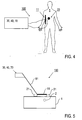
- FIG 4 schematically illustrates an embodiment whereas the invention is used for imaging a human being or a part thereof, e. g. an organ.
- the near-field source device 11, which comprises e.g. a single rod-shaped antenna element is arranged outside the body of the human patient 1.
- the distance between the antenna element and the outer surface of the human patient 1 greatly depends on the size of region-of-interest and spectrum emitted by the generator and may be selected in the range of 5 mm to 50 cm for most applications.
- the detector device 22, which comprises an array of detector elements 21 is arranged on the outer surface of the human patient 1 as well.
- a matching gel can be provided between the outer skin of the human patient 1 and the detector device 20.
- Both, the near-field source device 11 and the detector device 20 are connected with the components 30, 40 and 70 ( Figure 1 ).
- an agent is injected intravenously or locally to the patient 1, and targets areas or processes of interest.
- the near field emitting source (antenna element 13) is brought in the proximity of the tissue so that near-field energy is optimally coupled into it.
- the mechanical wave detector device 20 such as an acoustic detector or array of acoustic detectors 21 detects acoustic waves generated within the tissue.
- the collected data is processed and presented in the form of two- or three-dimensional image on the monitor.
- the apparatus is capable of real-time (30 or more frames per second) visualization of the imaged cross-section volume and specific bio-markers contained in it.
- An application example includes the administration of iron-oxide base nanoparticles (size e. g. on the order of 10 - 100 nm) that are preferentially uptaken by macrophages.
- Image of their absorption yields areas of increased inflammation as in the case of image atherosclerotic plaque, in the carotids or other vessels.
- targeted absorbing particles can show information on targeted molecules such as peptides, receptors etc.
- Another application example includes imaging of the effect of treatment, via drugs, radiation or chemotherapy, by similarly administrating absorbing particles in the body and monitoring their relative update or targeting over time.
- the same detection can be achieved by portable devices, or endoscopic devices inserted into body cavities or through invasive procedures by operatively inserting the device into the tissue.
- the imaging device 100 is provided as a hand-held, portable device including the near-field source device 11 and the detector device 20 at a free end of a support rod, whereas the components 30, 40 and 70 are arranged at the opposite and thereof. Components 30, 40 and 70 can be included in a box with a handle.
- the object 1 comprises e.g. food or a container, in which a certain component (ROI 2) is to be investigated.
- ROI 2 a certain component
- Other non-biological samples like ground or other geological structure can be investigated in an analogue way.
Landscapes
- Health & Medical Sciences (AREA)
- Life Sciences & Earth Sciences (AREA)
- Physics & Mathematics (AREA)
- Surgery (AREA)
- Medical Informatics (AREA)
- Pathology (AREA)
- Veterinary Medicine (AREA)
- Engineering & Computer Science (AREA)
- Biomedical Technology (AREA)
- Heart & Thoracic Surgery (AREA)
- Public Health (AREA)
- Molecular Biology (AREA)
- Biophysics (AREA)
- Animal Behavior & Ethology (AREA)
- General Health & Medical Sciences (AREA)
- Nuclear Medicine, Radiotherapy & Molecular Imaging (AREA)
- Radiology & Medical Imaging (AREA)
- Acoustics & Sound (AREA)
- Ultra Sonic Daignosis Equipment (AREA)
Priority Applications (4)
| Application Number | Priority Date | Filing Date | Title |
|---|---|---|---|
| US12/867,265 US20110040176A1 (en) | 2008-02-19 | 2009-02-18 | Method and device for near-field dual-wave modality imaging |
| EP09713467.0A EP2254467B1 (fr) | 2008-02-19 | 2009-02-18 | Procédé et dispositif pour l'imagerie de modalité à onde double à champ rapproché |
| PCT/EP2009/001137 WO2009103502A1 (fr) | 2008-02-19 | 2009-02-18 | Procédé et dispositif d’imagerie de modalité à onde double et champ proche |
| JP2010546271A JP2011512180A (ja) | 2008-02-19 | 2009-02-18 | 近接二重波撮像 |
Applications Claiming Priority (1)
| Application Number | Priority Date | Filing Date | Title |
|---|---|---|---|
| US6618708P | 2008-02-19 | 2008-02-19 |
Publications (1)
| Publication Number | Publication Date |
|---|---|
| EP2110076A1 true EP2110076A1 (fr) | 2009-10-21 |
Family
ID=39731282
Family Applications (2)
| Application Number | Title | Priority Date | Filing Date |
|---|---|---|---|
| EP08006528A Withdrawn EP2110076A1 (fr) | 2008-02-19 | 2008-03-31 | Procédé et dispositif pour l'imagerie de modalité à onde double à champ rapproché |
| EP09713467.0A Not-in-force EP2254467B1 (fr) | 2008-02-19 | 2009-02-18 | Procédé et dispositif pour l'imagerie de modalité à onde double à champ rapproché |
Family Applications After (1)
| Application Number | Title | Priority Date | Filing Date |
|---|---|---|---|
| EP09713467.0A Not-in-force EP2254467B1 (fr) | 2008-02-19 | 2009-02-18 | Procédé et dispositif pour l'imagerie de modalité à onde double à champ rapproché |
Country Status (4)
| Country | Link |
|---|---|
| US (1) | US20110040176A1 (fr) |
| EP (2) | EP2110076A1 (fr) |
| JP (1) | JP2011512180A (fr) |
| WO (1) | WO2009103502A1 (fr) |
Cited By (3)
| Publication number | Priority date | Publication date | Assignee | Title |
|---|---|---|---|---|
| EP2465428B1 (fr) * | 2010-12-15 | 2017-04-12 | Medielma S.r.l. | Système de détection électromagnétique et procédé pour localiser des tumeurs/calcifications dans des tissus |
| US10265047B2 (en) | 2014-03-12 | 2019-04-23 | Fujifilm Sonosite, Inc. | High frequency ultrasound transducer having an ultrasonic lens with integral central matching layer |
| US10478859B2 (en) | 2006-03-02 | 2019-11-19 | Fujifilm Sonosite, Inc. | High frequency ultrasonic transducer and matching layer comprising cyanoacrylate |
Families Citing this family (45)
| Publication number | Priority date | Publication date | Assignee | Title |
|---|---|---|---|---|
| FR2906369B1 (fr) * | 2006-09-25 | 2009-03-06 | Satimo Sa | Dispositif micro-onde de controle d'un materiau |
| US8989837B2 (en) | 2009-12-01 | 2015-03-24 | Kyma Medical Technologies Ltd. | Methods and systems for determining fluid content of tissue |
| US9572497B2 (en) | 2008-07-25 | 2017-02-21 | Helmholtz Zentrum Munchen Deutsches Forschungszentrum Fur Gesundheit Und Umwelt (Gmbh) | Quantitative multi-spectral opto-acoustic tomography (MSOT) of tissue biomarkers |
| JP5566456B2 (ja) | 2009-06-29 | 2014-08-06 | ヘルムホルツ・ツェントルム・ミュンヒェン・ドイチェス・フォルシュンクスツェントルム・フューア・ゲズントハイト・ウント・ウムベルト(ゲーエムベーハー) | 被写体を熱音響撮像するための撮像装置及び撮像方法、コンピュータプログラム並びにコンピュータで読み取り可能な記憶媒体を備える装置 |
| EP2459987A1 (fr) | 2009-07-27 | 2012-06-06 | Helmholtz Zentrum München Deutsches Forschungszentrum für Gesundheit und Umwelt (GmbH) | Dispositif d'imagerie et procédé pour l'imagerie opto-acoustique de petits animaux |
| US9255914B2 (en) * | 2009-08-13 | 2016-02-09 | Kabushiki Kaisha Toshiba | Ultrasonic diagnosis apparatus and program |
| CA2782499A1 (fr) * | 2009-12-01 | 2011-06-09 | Kyma Medical Technologies Ltd. | Localisation de caracteristiques dans le cur a l'aide de systeme d'imagerie radiofrequence |
| US9451924B2 (en) * | 2009-12-30 | 2016-09-27 | General Electric Company | Single screen multi-modality imaging displays |
| JP6081355B2 (ja) | 2010-07-21 | 2017-02-15 | キマ メディカル テクノロジーズ リミテッド | 埋込み式無線周波数センサ |
| US8779966B2 (en) * | 2010-11-16 | 2014-07-15 | Tialinx, Inc. | Remote interrogation for detection of activity or living organisms inside electronically conductive containers |
| US9448187B2 (en) * | 2011-07-01 | 2016-09-20 | University Of Manitoba | Imaging using probes |
| US20130013239A1 (en) * | 2011-07-08 | 2013-01-10 | General Electric Company | System and method for excitation generation in soft-field tomography |
| US8963562B2 (en) | 2011-08-31 | 2015-02-24 | General Electric Company | Transducer configurations and methods for transducer positioning in electrical impedance tomography |
| US20150366458A1 (en) | 2012-05-07 | 2015-12-24 | Helmholtz Zentrum Munchen Deutsches Forschungszentrum Fur Gesundheit Und Umwelt (Gmbh) | Apparatus and method for frequency-domain thermo-acoustic tomographic imaging |
| JP2014066701A (ja) * | 2012-09-04 | 2014-04-17 | Canon Inc | 被検体情報取得装置 |
| SE536842C2 (sv) * | 2012-09-24 | 2014-09-30 | Totalförsvarets Forskningsinstitut FOI | Anordning och metod för att på avstånd fastställa impulssvaret hos ett objekt med hjälp av elektromagnetisk strålning |
| US9073347B2 (en) * | 2012-10-11 | 2015-07-07 | Geophysical Survey Systems, Inc. | Hand-held radar device with direct printing based on radar input |
| EP2742854B1 (fr) | 2012-12-11 | 2021-03-10 | iThera Medical GmbH | Dispositif portatif et procédé pour imagerie opto-acoustique tomographique d'un objet |
| EP2754388B1 (fr) | 2013-01-15 | 2020-09-09 | Helmholtz Zentrum München Deutsches Forschungszentrum für Gesundheit und Umwelt GmbH | Système et procédé pour imagerie opto-acoustique à haut débit de meilleure qualité d'un objet |
| DE102013005095A1 (de) * | 2013-03-23 | 2014-09-25 | Diehl Bgt Defence Gmbh & Co. Kg | Vorrichtung zur Erzeugung von Mikrowellen |
| US20150250388A1 (en) * | 2013-07-10 | 2015-09-10 | The Board Of Trustees Of The Leland Stanford Junior University | Remote sensing, imaging, or screening of embedded or concealed objects |
| EP2829872A1 (fr) * | 2013-07-26 | 2015-01-28 | Helmholtz Zentrum München Deutsches Forschungszentrum für Gesundheit und Umwelt GmbH | Dispositif capteur et procédé pour détecter des réponses thermoacoustiques d'un milieu |
| EP2829871A1 (fr) * | 2013-07-26 | 2015-01-28 | Helmholtz Zentrum München Forschungszentrum für Gesundheit und Umwelt GmbH | Dispositif capteur et procédé de mesure thermoacoustique de champs électromagnétiques |
| EP3063832B1 (fr) | 2013-10-29 | 2022-07-06 | Zoll Medical Israel Ltd. | Systèmes et dispositifs d'antenne, et procédés de fabrication associés |
| WO2015077088A1 (fr) | 2013-11-22 | 2015-05-28 | Massachusetts Institute Of Technology | Système et procédé pour ultrason sans contact |
| US10716488B2 (en) | 2013-12-30 | 2020-07-21 | The University Of Manitoba | Imaging using gated elements |
| US11013420B2 (en) | 2014-02-05 | 2021-05-25 | Zoll Medical Israel Ltd. | Systems, apparatuses and methods for determining blood pressure |
| US9372256B2 (en) * | 2014-02-26 | 2016-06-21 | Farrokh Mohamadi | Wafer scale sensor ultra-wideband array for tissue diagnosis |
| US10856740B2 (en) * | 2014-03-03 | 2020-12-08 | The Board Of Trustees Of The Leland Stanford Junior University | Coherent frequency-domain microwave-induced thermoacoustic imaging |
| US9959477B2 (en) | 2014-03-03 | 2018-05-01 | The Board Of Trustees Of The Leland Stanford Junior University | Mapping of blood vessels for biometric authentication |
| WO2016005909A1 (fr) | 2014-07-07 | 2016-01-14 | University Of Manitoba | Imagerie à l'aide d'antennes reconfigurables |
| US11259715B2 (en) | 2014-09-08 | 2022-03-01 | Zoll Medical Israel Ltd. | Monitoring and diagnostics systems and methods |
| WO2016115175A1 (fr) | 2015-01-12 | 2016-07-21 | KYMA Medical Technologies, Inc. | Systèmes, appareils et procédés permettant de détecter par radio-fréquences la fixation d'un appareil |
| WO2016193554A1 (fr) * | 2015-06-02 | 2016-12-08 | Centre National De La Recherche Scientifique - Cnrs - | Procedes et systemes d'imagerie acousto-optique |
| CN104887272B (zh) * | 2015-06-26 | 2017-09-19 | 四川大学 | 电磁波热致超声波成像激励源及其构成的成像设备 |
| KR20170007181A (ko) | 2015-07-10 | 2017-01-18 | 3스캔 인크. | 조직학적 염색제의 공간 다중화 |
| US10022107B2 (en) * | 2015-07-31 | 2018-07-17 | Endra Life Sciences Inc. | Method and system for correcting fat-induced aberrations |
| US11266315B2 (en) * | 2015-12-04 | 2022-03-08 | The Research Foundation For The State University Of New York | Devices and methods for photoacoustic tomography |
| WO2017160858A1 (fr) | 2016-03-14 | 2017-09-21 | Massachusetts Institute Of Technology | Système et procédé d'imagerie ultrasonore sans contact avec sécurité améliorée |
| WO2017197165A1 (fr) * | 2016-05-12 | 2017-11-16 | The Board Of Trustees Of The Leland Stanford Junior University | Sonde de détection de l'athérosclérose |
| US20180055369A1 (en) * | 2016-08-31 | 2018-03-01 | Qualcomm Incorporated | Layered sensing including rf-acoustic imaging |
| EP3351168B1 (fr) * | 2017-01-20 | 2019-12-04 | Nokia Technologies Oy | Mesure de pouls artériel |
| EP3366221A1 (fr) | 2017-02-28 | 2018-08-29 | Koninklijke Philips N.V. | Système intelligent à ultrasons |
| US11020002B2 (en) | 2017-08-10 | 2021-06-01 | Zoll Medical Israel Ltd. | Systems, devices and methods for physiological monitoring of patients |
| WO2019170926A1 (fr) | 2018-03-06 | 2019-09-12 | Promocion Y Desarrollo De Sistemas Automaticos S.L. | Procédé et dispositif de caractérisation d'un champ électromagnétique, et procédé et dispositif d'inspection non destructive au moyen de l'utilisation d'un champ électromagnétique |
Citations (10)
| Publication number | Priority date | Publication date | Assignee | Title |
|---|---|---|---|---|
| US4255971A (en) | 1978-11-01 | 1981-03-17 | Allan Rosencwaig | Thermoacoustic microscopy |
| US4343993A (en) | 1979-09-20 | 1982-08-10 | International Business Machines Corporation | Scanning tunneling microscope |
| US4770183A (en) | 1986-07-03 | 1988-09-13 | Advanced Magnetics Incorporated | Biologically degradable superparamagnetic particles for use as nuclear magnetic resonance imaging agents |
| EP0459392A2 (fr) * | 1990-05-30 | 1991-12-04 | Hitachi, Ltd. | Procédé et dispositif pour le traitement d'une partie très petite d'un échantillon |
| US6216025B1 (en) | 1999-02-02 | 2001-04-10 | Optosonics, Inc. | Thermoacoustic computed tomography scanner |
| US6567688B1 (en) | 1999-08-19 | 2003-05-20 | The Texas A&M University System | Methods and apparatus for scanning electromagnetically-induced thermoacoustic tomography |
| EP1333703A2 (fr) * | 2002-01-30 | 2003-08-06 | Lg Electronics Inc. | Four à micro-ondes comportant une structure d'étanchéité ainsi que le four à micro-ondes en étant équipé |
| US6662040B1 (en) | 1997-06-16 | 2003-12-09 | Amersham Health As | Methods of photoacoustic imaging |
| US7005653B1 (en) | 2002-06-18 | 2006-02-28 | Nanopoint, Inc. | Near-field intra-cellular apertureless tomographic imaging |
| JP2007307007A (ja) * | 2006-05-17 | 2007-11-29 | Hamamatsu Kagaku Gijutsu Kenkyu Shinkokai | 光音響効果を用いたカテーテルシステム |
Family Cites Families (48)
| Publication number | Priority date | Publication date | Assignee | Title |
|---|---|---|---|---|
| US4358634A (en) * | 1980-04-24 | 1982-11-09 | Thomas & Betts Corporation | Protective cover for use in sealed cable splices |
| US5840023A (en) * | 1996-01-31 | 1998-11-24 | Oraevsky; Alexander A. | Optoacoustic imaging for medical diagnosis |
| US6173604B1 (en) * | 1996-09-20 | 2001-01-16 | The Regents Of The University Of California | Scanning evanescent electro-magnetic microscope |
| US5713356A (en) * | 1996-10-04 | 1998-02-03 | Optosonics, Inc. | Photoacoustic breast scanner |
| US6208749B1 (en) * | 1997-02-28 | 2001-03-27 | Electro-Optical Sciences, Inc. | Systems and methods for the multispectral imaging and characterization of skin tissue |
| US5928151A (en) * | 1997-08-22 | 1999-07-27 | Acuson Corporation | Ultrasonic system and method for harmonic imaging in three dimensions |
| US6477398B1 (en) * | 1997-11-13 | 2002-11-05 | Randell L. Mills | Resonant magnetic susceptibility imaging (ReMSI) |
| US6760609B2 (en) * | 1999-07-14 | 2004-07-06 | Providence Health System - Oregon | Adaptive calibration pulsed oximetry method and device |
| TW579435B (en) * | 1999-08-02 | 2004-03-11 | Zetetic Inst | Scanning interferometric near-field confocal microscopy |
| US6424410B1 (en) * | 1999-08-27 | 2002-07-23 | Maui Innovative Peripherals, Inc. | 3D navigation system using complementary head-mounted and stationary infrared beam detection units |
| US6834063B2 (en) * | 2000-01-06 | 2004-12-21 | Raytheon Company | Efficient angle tunable output from a monolithic serial KTA optical parametric oscillator |
| AU2001225435A1 (en) * | 2000-01-11 | 2001-07-24 | Marcel Guillong | Radially homogeneous high energy density uv sample ablating laser radiation in "pure" solid to gas sample preparation, for analysis by icp-ms and icp-oes |
| US6180087B1 (en) * | 2000-01-18 | 2001-01-30 | Mallinckrodt Inc. | Tunable indocyanine dyes for biomedical applications |
| US6847168B1 (en) * | 2000-08-01 | 2005-01-25 | Calabazas Creek Research, Inc. | Electron gun for a multiple beam klystron using magnetic focusing with a magnetic field corrector |
| US6615063B1 (en) * | 2000-11-27 | 2003-09-02 | The General Hospital Corporation | Fluorescence-mediated molecular tomography |
| US20020073717A1 (en) * | 2000-12-19 | 2002-06-20 | Dean David E. | MR scanner including liquid cooled RF coil and method |
| US7498564B2 (en) * | 2001-02-06 | 2009-03-03 | University Of Bristol Of Senate House | Resonant scanning near-field optical microscope |
| DE10113661A1 (de) * | 2001-03-21 | 2002-09-26 | Philips Corp Intellectual Pty | Katheter zur Anwendung in einem Magnetresonanz-Bildgerät |
| US6498492B1 (en) * | 2001-03-23 | 2002-12-24 | Rosemount Analytical Inc. | Process of measuring conductivity using a pH analyzer |
| US6490470B1 (en) * | 2001-06-19 | 2002-12-03 | Optosonics, Inc. | Thermoacoustic tissue scanner |
| GB0126804D0 (en) * | 2001-11-07 | 2002-01-02 | Univ London | Flow velocity measurement |
| US6700459B2 (en) * | 2002-05-29 | 2004-03-02 | Superconductor Technologies, Inc. | Dual-mode bandpass filter with direct capacitive couplings and far-field suppression structures |
| US20040059265A1 (en) * | 2002-09-12 | 2004-03-25 | The Regents Of The University Of California | Dynamic acoustic focusing utilizing time reversal |
| US7774042B2 (en) * | 2002-09-26 | 2010-08-10 | Senco Brands, Inc. | Tissue scanner |
| US7500953B2 (en) * | 2003-01-25 | 2009-03-10 | Seno Medical Instruments, Inc. | High contrast optoacoustic imaging using nanoparticles |
| US7551957B2 (en) * | 2003-03-06 | 2009-06-23 | Bioelectronics Corp. | Electromagnetic therapy device and methods |
| US7720525B2 (en) * | 2003-03-12 | 2010-05-18 | New Art Advanced Research Technologies Inc. | Method and apparatus for combining continuous wave and time domain optical imaging |
| IES20030396A2 (en) * | 2003-05-23 | 2004-11-17 | Univ Dublin City | A method and apparatus for analysis of semiconductor materials using photoacoustic spectroscopy techniques |
| US7725151B2 (en) * | 2003-06-02 | 2010-05-25 | Van Der Weide Daniel Warren | Apparatus and method for near-field imaging of tissue |
| US7298869B1 (en) * | 2003-07-21 | 2007-11-20 | Abernathy Donald A | Multispectral data acquisition system and method |
| IL164030A0 (en) * | 2003-09-12 | 2005-12-18 | Revital Pery Shechter | Photoacoustic analyzer of a region of interest in a human body |
| WO2005107592A1 (fr) * | 2004-05-06 | 2005-11-17 | Nippon Telegraph And Telephone Corporation | Dispositif de mesure de concentration de composant et méthode de contrôle de dispositif de mesure de concentration de composant |
| US7471975B2 (en) * | 2004-09-22 | 2008-12-30 | The Research Foundation Of State University Of New York | Optical tensor imaging |
| US20060084861A1 (en) * | 2004-10-18 | 2006-04-20 | Topspin Medical (Isreal) Ltd. | Magnet and coil configurations for MRI probes |
| IL166408A0 (en) * | 2005-01-20 | 2006-01-15 | Ultraview Ltd | Combined 2d pulse-echo ultrasound and optoacousticsignal for glaucoma treatment |
| US20060184042A1 (en) * | 2005-01-22 | 2006-08-17 | The Texas A&M University System | Method, system and apparatus for dark-field reflection-mode photoacoustic tomography |
| US7247842B1 (en) * | 2005-07-12 | 2007-07-24 | California Institute Of Technology | Method and system for scanning apertureless fluorescence mircroscope |
| US8660631B2 (en) * | 2005-09-08 | 2014-02-25 | Bruker Biospin Corporation | Torsional support apparatus and method for craniocaudal rotation of animals |
| WO2007058895A2 (fr) * | 2005-11-11 | 2007-05-24 | Visualsonics Inc. | Accentuation de contraste par image de recouvrement |
| US20090054763A1 (en) * | 2006-01-19 | 2009-02-26 | The Regents Of The University Of Michigan | System and method for spectroscopic photoacoustic tomography |
| US7741045B2 (en) * | 2006-11-16 | 2010-06-22 | General Electric Company | Sequential analysis of biological samples |
| US20080221647A1 (en) * | 2007-02-23 | 2008-09-11 | The Regents Of The University Of Michigan | System and method for monitoring photodynamic therapy |
| US8251909B2 (en) * | 2007-07-16 | 2012-08-28 | Arnold Stephen C | Acoustic imaging probe incorporating photoacoustic excitation |
| US20090058746A1 (en) * | 2007-08-31 | 2009-03-05 | Harris Corporation | Evanescent wave-coupled frequency selective surface |
| WO2010048258A1 (fr) * | 2008-10-23 | 2010-04-29 | Washington University In St. Louis | Tomographie photoacoustique à mode de réflexion utilisant une poutre en porte-à-faux supportée de façon souple |
| WO2009073979A1 (fr) * | 2007-12-12 | 2009-06-18 | Carson Jeffrey J L | Imageur photo-acoustique tridimensionnel et procédés de calibrage d'un imageur |
| US20110306865A1 (en) * | 2008-09-10 | 2011-12-15 | Endra, Inc. | photoacoustic imaging device |
| JP5574674B2 (ja) * | 2009-11-12 | 2014-08-20 | キヤノン株式会社 | 音響波測定装置 |
-
2008
- 2008-03-31 EP EP08006528A patent/EP2110076A1/fr not_active Withdrawn
-
2009
- 2009-02-18 WO PCT/EP2009/001137 patent/WO2009103502A1/fr not_active Ceased
- 2009-02-18 US US12/867,265 patent/US20110040176A1/en not_active Abandoned
- 2009-02-18 JP JP2010546271A patent/JP2011512180A/ja active Pending
- 2009-02-18 EP EP09713467.0A patent/EP2254467B1/fr not_active Not-in-force
Patent Citations (10)
| Publication number | Priority date | Publication date | Assignee | Title |
|---|---|---|---|---|
| US4255971A (en) | 1978-11-01 | 1981-03-17 | Allan Rosencwaig | Thermoacoustic microscopy |
| US4343993A (en) | 1979-09-20 | 1982-08-10 | International Business Machines Corporation | Scanning tunneling microscope |
| US4770183A (en) | 1986-07-03 | 1988-09-13 | Advanced Magnetics Incorporated | Biologically degradable superparamagnetic particles for use as nuclear magnetic resonance imaging agents |
| EP0459392A2 (fr) * | 1990-05-30 | 1991-12-04 | Hitachi, Ltd. | Procédé et dispositif pour le traitement d'une partie très petite d'un échantillon |
| US6662040B1 (en) | 1997-06-16 | 2003-12-09 | Amersham Health As | Methods of photoacoustic imaging |
| US6216025B1 (en) | 1999-02-02 | 2001-04-10 | Optosonics, Inc. | Thermoacoustic computed tomography scanner |
| US6567688B1 (en) | 1999-08-19 | 2003-05-20 | The Texas A&M University System | Methods and apparatus for scanning electromagnetically-induced thermoacoustic tomography |
| EP1333703A2 (fr) * | 2002-01-30 | 2003-08-06 | Lg Electronics Inc. | Four à micro-ondes comportant une structure d'étanchéité ainsi que le four à micro-ondes en étant équipé |
| US7005653B1 (en) | 2002-06-18 | 2006-02-28 | Nanopoint, Inc. | Near-field intra-cellular apertureless tomographic imaging |
| JP2007307007A (ja) * | 2006-05-17 | 2007-11-29 | Hamamatsu Kagaku Gijutsu Kenkyu Shinkokai | 光音響効果を用いたカテーテルシステム |
Non-Patent Citations (1)
| Title |
|---|
| ASH, E.A. ET AL.: "Super-Resolution Aperture Scanning Microscope", NATURE, vol. 237, June 1972 (1972-06-01), pages 510 - 512 |
Cited By (5)
| Publication number | Priority date | Publication date | Assignee | Title |
|---|---|---|---|---|
| US10478859B2 (en) | 2006-03-02 | 2019-11-19 | Fujifilm Sonosite, Inc. | High frequency ultrasonic transducer and matching layer comprising cyanoacrylate |
| EP2465428B1 (fr) * | 2010-12-15 | 2017-04-12 | Medielma S.r.l. | Système de détection électromagnétique et procédé pour localiser des tumeurs/calcifications dans des tissus |
| US10265047B2 (en) | 2014-03-12 | 2019-04-23 | Fujifilm Sonosite, Inc. | High frequency ultrasound transducer having an ultrasonic lens with integral central matching layer |
| US11083433B2 (en) | 2014-03-12 | 2021-08-10 | Fujifilm Sonosite, Inc. | Method of manufacturing high frequency ultrasound transducer having an ultrasonic lens with integral central matching layer |
| US11931203B2 (en) | 2014-03-12 | 2024-03-19 | Fujifilm Sonosite, Inc. | Manufacturing method of a high frequency ultrasound transducer having an ultrasonic lens with integral central matching layer |
Also Published As
| Publication number | Publication date |
|---|---|
| WO2009103502A1 (fr) | 2009-08-27 |
| US20110040176A1 (en) | 2011-02-17 |
| JP2011512180A (ja) | 2011-04-21 |
| EP2254467B1 (fr) | 2015-04-08 |
| EP2254467A1 (fr) | 2010-12-01 |
Similar Documents
| Publication | Publication Date | Title |
|---|---|---|
| EP2254467B1 (fr) | Procédé et dispositif pour l'imagerie de modalité à onde double à champ rapproché | |
| US6567688B1 (en) | Methods and apparatus for scanning electromagnetically-induced thermoacoustic tomography | |
| Liu et al. | Biomedical microwave-induced thermoacoustic imaging | |
| Ke et al. | Performance characterization of an integrated ultrasound, photoacoustic, and thermoacoustic imaging system | |
| US20150366458A1 (en) | Apparatus and method for frequency-domain thermo-acoustic tomographic imaging | |
| Emelianov et al. | Photoacoustics for molecular imaging and therapy | |
| US6974415B2 (en) | Electromagnetic-acoustic imaging | |
| Mariappan et al. | Magneto acoustic tomography with short pulsed magnetic field for in-vivo imaging of magnetic iron oxide nanoparticles | |
| CN114176554B (zh) | 多脉宽微波激励多尺度热声成像方法及系统 | |
| Huang et al. | Design of a handheld dipole antenna for a compact thermoacoustic imaging system | |
| CN1261259A (zh) | 电子成像和治疗系统 | |
| JP5197217B2 (ja) | 生体情報イメージング装置、画像構成方法 | |
| EP2829872A1 (fr) | Dispositif capteur et procédé pour détecter des réponses thermoacoustiques d'un milieu | |
| Xu et al. | Nonlinear thermoacoustic imaging based on temperature-dependent thermoelastic response | |
| Zhao et al. | System development of microwave induced thermo-acoustic tomography and experiments on breast tumor | |
| Ren et al. | Portable microwave-acoustic coaxial thermoacoustic probe with miniaturized vivaldi antennas for breast tumor screening | |
| Chaplin et al. | Multi-focal HIFU reduces cavitation in mild-hyperthermia | |
| Zhang et al. | Real-time interleaved photoacoustic and ultrasound imaging for guiding interventional procedures | |
| Zhang et al. | In vivo microwave-induced thermoacoustic endoscopy for colorectal tumor detection in deep tissue | |
| Wang et al. | High-spatiotemporal resolution microwave-induced thermoacoustic tomography for imaging biological dynamics in deep tissue | |
| Liu et al. | Developing microwave-induced thermoacoustic tomography: system, application, and reconstruction | |
| Bitton et al. | A 3-D high-frequency array based 16 channel photoacoustic microscopy system for in vivo micro-vascular imaging | |
| Islam et al. | Evaluation of a low-cost amplifier with system optimization in thermoacoustic tomography: Characterization and imaging of ex-vivo and in-vivo samples | |
| Lin | Microwave thermoelastic tomography and imaging | |
| Xu et al. | A novel monitoring technique for breast cancer hyperthermia using thermoacoustic imaging |
Legal Events
| Date | Code | Title | Description |
|---|---|---|---|
| PUAI | Public reference made under article 153(3) epc to a published international application that has entered the european phase |
Free format text: ORIGINAL CODE: 0009012 |
|
| AK | Designated contracting states |
Kind code of ref document: A1 Designated state(s): AT BE BG CH CY CZ DE DK EE ES FI FR GB GR HR HU IE IS IT LI LT LU LV MC MT NL NO PL PT RO SE SI SK TR |
|
| AX | Request for extension of the european patent |
Extension state: AL BA MK RS |
|
| AKX | Designation fees paid | ||
| STAA | Information on the status of an ep patent application or granted ep patent |
Free format text: STATUS: THE APPLICATION IS DEEMED TO BE WITHDRAWN |
|
| 18D | Application deemed to be withdrawn |
Effective date: 20100422 |
|
| REG | Reference to a national code |
Ref country code: DE Ref legal event code: 8566 |