EP2110077A1 - Vorrichtung und Verfahren zur Messung der Belastung des Kreuzbandes des Knies - Google Patents
Vorrichtung und Verfahren zur Messung der Belastung des Kreuzbandes des Knies Download PDFInfo
- Publication number
- EP2110077A1 EP2110077A1 EP08154617A EP08154617A EP2110077A1 EP 2110077 A1 EP2110077 A1 EP 2110077A1 EP 08154617 A EP08154617 A EP 08154617A EP 08154617 A EP08154617 A EP 08154617A EP 2110077 A1 EP2110077 A1 EP 2110077A1
- Authority
- EP
- European Patent Office
- Prior art keywords
- predetermined
- foot
- force
- tibia
- support platform
- Prior art date
- Legal status (The legal status is an assumption and is not a legal conclusion. Google has not performed a legal analysis and makes no representation as to the accuracy of the status listed.)
- Granted
Links
- 238000005259 measurement Methods 0.000 title claims description 17
- 238000000034 method Methods 0.000 title claims description 14
- 210000003127 knee Anatomy 0.000 title description 20
- 210000003041 ligament Anatomy 0.000 title description 3
- 210000002683 foot Anatomy 0.000 claims abstract description 82
- 210000002303 tibia Anatomy 0.000 claims abstract description 56
- 210000000689 upper leg Anatomy 0.000 claims abstract description 46
- 238000006073 displacement reaction Methods 0.000 claims abstract description 38
- 210000003423 ankle Anatomy 0.000 claims abstract description 19
- 238000012360 testing method Methods 0.000 claims abstract description 15
- 210000004417 patella Anatomy 0.000 claims description 12
- 210000001699 lower leg Anatomy 0.000 claims description 8
- 241001227561 Valgus Species 0.000 claims description 2
- 241000469816 Varus Species 0.000 claims description 2
- 230000000063 preceeding effect Effects 0.000 claims 6
- 210000001264 anterior cruciate ligament Anatomy 0.000 description 2
- 210000002414 leg Anatomy 0.000 description 2
- 210000001872 metatarsal bone Anatomy 0.000 description 2
- 210000002967 posterior cruciate ligament Anatomy 0.000 description 2
- 239000002775 capsule Substances 0.000 description 1
- 230000001419 dependent effect Effects 0.000 description 1
- 238000011156 evaluation Methods 0.000 description 1
- 210000004744 fore-foot Anatomy 0.000 description 1
- 208000014674 injury Diseases 0.000 description 1
- 230000007935 neutral effect Effects 0.000 description 1
- 230000000399 orthopedic effect Effects 0.000 description 1
- 230000002980 postoperative effect Effects 0.000 description 1
- 230000006641 stabilisation Effects 0.000 description 1
- 238000011105 stabilization Methods 0.000 description 1
- 210000003371 toe Anatomy 0.000 description 1
- 238000013519 translation Methods 0.000 description 1
- 230000008733 trauma Effects 0.000 description 1
Images

Classifications
-
- A—HUMAN NECESSITIES
- A61—MEDICAL OR VETERINARY SCIENCE; HYGIENE
- A61B—DIAGNOSIS; SURGERY; IDENTIFICATION
- A61B5/00—Measuring for diagnostic purposes; Identification of persons
- A61B5/103—Measuring devices for testing the shape, pattern, colour, size or movement of the body or parts thereof, for diagnostic purposes
- A61B5/11—Measuring movement of the entire body or parts thereof, e.g. head or hand tremor or mobility of a limb
- A61B5/1121—Determining geometric values, e.g. centre of rotation or angular range of movement
-
- A—HUMAN NECESSITIES
- A61—MEDICAL OR VETERINARY SCIENCE; HYGIENE
- A61B—DIAGNOSIS; SURGERY; IDENTIFICATION
- A61B5/00—Measuring for diagnostic purposes; Identification of persons
- A61B5/103—Measuring devices for testing the shape, pattern, colour, size or movement of the body or parts thereof, for diagnostic purposes
- A61B5/107—Measuring physical dimensions, e.g. size of the entire body or parts thereof
- A61B5/1071—Measuring physical dimensions, e.g. size of the entire body or parts thereof measuring angles, e.g. using goniometers
-
- A—HUMAN NECESSITIES
- A61—MEDICAL OR VETERINARY SCIENCE; HYGIENE
- A61B—DIAGNOSIS; SURGERY; IDENTIFICATION
- A61B5/00—Measuring for diagnostic purposes; Identification of persons
- A61B5/103—Measuring devices for testing the shape, pattern, colour, size or movement of the body or parts thereof, for diagnostic purposes
- A61B5/11—Measuring movement of the entire body or parts thereof, e.g. head or hand tremor or mobility of a limb
- A61B5/1124—Determining motor skills
-
- A—HUMAN NECESSITIES
- A61—MEDICAL OR VETERINARY SCIENCE; HYGIENE
- A61B—DIAGNOSIS; SURGERY; IDENTIFICATION
- A61B5/00—Measuring for diagnostic purposes; Identification of persons
- A61B5/45—For evaluating or diagnosing the musculoskeletal system or teeth
- A61B5/4533—Ligaments
-
- A—HUMAN NECESSITIES
- A61—MEDICAL OR VETERINARY SCIENCE; HYGIENE
- A61B—DIAGNOSIS; SURGERY; IDENTIFICATION
- A61B5/00—Measuring for diagnostic purposes; Identification of persons
- A61B5/68—Arrangements of detecting, measuring or recording means, e.g. sensors, in relation to patient
- A61B5/6801—Arrangements of detecting, measuring or recording means, e.g. sensors, in relation to patient specially adapted to be attached to or worn on the body surface
- A61B5/6813—Specially adapted to be attached to a specific body part
- A61B5/6828—Leg
-
- A—HUMAN NECESSITIES
- A61—MEDICAL OR VETERINARY SCIENCE; HYGIENE
- A61B—DIAGNOSIS; SURGERY; IDENTIFICATION
- A61B5/00—Measuring for diagnostic purposes; Identification of persons
- A61B5/70—Means for positioning the patient in relation to the detecting, measuring or recording means
- A61B5/702—Posture restraints
-
- A—HUMAN NECESSITIES
- A61—MEDICAL OR VETERINARY SCIENCE; HYGIENE
- A61B—DIAGNOSIS; SURGERY; IDENTIFICATION
- A61B5/00—Measuring for diagnostic purposes; Identification of persons
- A61B5/68—Arrangements of detecting, measuring or recording means, e.g. sensors, in relation to patient
- A61B5/6801—Arrangements of detecting, measuring or recording means, e.g. sensors, in relation to patient specially adapted to be attached to or worn on the body surface
- A61B5/6813—Specially adapted to be attached to a specific body part
- A61B5/6829—Foot or ankle
-
- A—HUMAN NECESSITIES
- A61—MEDICAL OR VETERINARY SCIENCE; HYGIENE
- A61B—DIAGNOSIS; SURGERY; IDENTIFICATION
- A61B5/00—Measuring for diagnostic purposes; Identification of persons
- A61B5/68—Arrangements of detecting, measuring or recording means, e.g. sensors, in relation to patient
- A61B5/6801—Arrangements of detecting, measuring or recording means, e.g. sensors, in relation to patient specially adapted to be attached to or worn on the body surface
- A61B5/683—Means for maintaining contact with the body
- A61B5/6831—Straps, bands or harnesses
-
- A—HUMAN NECESSITIES
- A61—MEDICAL OR VETERINARY SCIENCE; HYGIENE
- A61H—PHYSICAL THERAPY APPARATUS, e.g. DEVICES FOR LOCATING OR STIMULATING REFLEX POINTS IN THE BODY; ARTIFICIAL RESPIRATION; MASSAGE; BATHING DEVICES FOR SPECIAL THERAPEUTIC OR HYGIENIC PURPOSES OR SPECIFIC PARTS OF THE BODY
- A61H1/00—Apparatus for passive exercising; Vibrating apparatus; Chiropractic devices, e.g. body impacting devices, external devices for briefly extending or aligning unbroken bones
- A61H1/02—Stretching or bending or torsioning apparatus for exercising
- A61H1/0237—Stretching or bending or torsioning apparatus for exercising for the lower limbs
- A61H1/024—Knee
Definitions
- the invention relates to a medical device and a method for measuring displacement of the proximal tibia relative to the distal femur as a result of applied forces.
- the invention comprises a foot support platform 13 which can be tilted about at least two axes.
- the first axis is close to the ankle 43 and approximately parallel to the coronal plane of a patient's body. Tilting about this axis results in dorsiflexion of the foot 42, increasing the dorsiflexion angle of the ankle (neutral zero method).
- the second axis is at right angle to the first axis and again approximately at the ankle 43, but approximately parallel to the tibia 46, thus permitting the foot 42 to perform internal and external rotation.
- the second axis may also deviate from the axis of the tibia by a predetermined angle or the angle from the tilt on the first axis.
- an optional thigh support platform 51 is provided to support the thigh 40 and bring the knee 44 into a predetermined angle, preferably in the range of 10 to 40 degrees, most preferably 30 degrees or 90 degrees.
- the patient Before performing a measurement with the displacement test device 60, the patient is placed with his knee 44 on the thigh support platform 51 and the foot 42 is placed on the foot support platform 30.
- the foot 42 is fixed on the platform 30 either with straps 32 or with a fixation frame 31 or by any other adequate means or a combination thereof.
- a fixation allows precise rotation.
- the foot is fixed within the foot support platform by the posterior area of the heel and the metatarsal head 1 and 5.
- the frame 31 is adjustable to fit exactly to the width of the foot between metatarsal heads 1 and 5. Such adjustment may be performed by adjustment screws 33 movable in slots.
- the foot support platform 30 is placed into an upright position close to the natural position of the foot.
- the foot support platform is tilted around the first axis by the first shaft 10, so that the forefoot moves into dorsiflexion. Tilting should be done in such a way that maximum dorsiflexion is obtained.
- This tilt is either performed at a constant angle or at a constant force.
- a constant force is applied and the resulting angle is measured.
- the force is adjusted to obtain maximum dorsiflexion. By this flexion the upper ankle is locked in rotation.
- the value of the constant force may be a predetermined value, preferable in a range of 2 N to 15 N. It is further preferred to apply a predetermined torque instead of a predetermined force.
- the torque may be directly applied to the first shaft by means of a drive motor or by a torque wrench.
- the torque may be any predetermined value, preferable in a range of 1 Nm to 15 Nm. Most preferably the range is between 1 Nm to 10 Nm.
- the foot 42 is rotated into predetermined positions by rotating the second shaft 20. This can be done either by applying a predetermined rotational angle or by applying a predetermined force or torque to rotate the foot against the left and right end positions. Doing so imposes a torque on the knee 44 because the tibia 46 cannot rotate relative to the foot 42 as it has been locked in the previous flexion on the first shaft 10.
- the inventive device is used for measuring the necessary force or torque for obtaining a rotation through a predetermined angle, or measuring the rotated angle after applying a predetermined force or torque to rotate the foot.
- the respective measurement devices for measuring force, torque or angle are optionally provided.
- a displacement test device 60 applies a predetermined force or torque to the tibia and measures displacement of the proximal tibia 46 relative to the distal femur 56. Such a force may be applied in any direction, preferably at right angles to the tibia. This measurement is also referred to as anterior posterior translation measurement. Such a measurement can be repeated with various displacement angles of the foot 42 around the second shaft.
- a displacement test device 60 is provided as disclosed in US 4,583,555 for specifically performing a drawer shift measurement. This document is included herein by reference. It applies a predetermined force to the tibia and permits measurement of the displacement between the proximate tibia and the distal femur.
- At least one side stop 65 is provided for applying varus - valgus stress on the medial or lateral epicondyle of the distal femur.
- a side stop may be manually or automatically driven or positioned to fix the distal femur at a predetermined position.
- the side stops may impose a predetermined force on either side of the distal femur.
- Drive means may be provided to move the side stops.
- first and second shafts hinges or other means for allowing a tilt of the foot support platform also may be used.
- first and second shafts may be driven by a DC motor, a stepper motor or a torque wrench.
- a drive means has means for stopping tilt and/or rotation motion after a predetermined position and/or a predetermined force has been reached.
- a method for measuring the anterior or posterior displacement of the proximal tibia 46 relative to the distal femur 56 as a result of applied forces comprises the following steps:
- a shifting of the top section of the foot 42 close to the toes towards the body of the patient is a shifting of the top section of the foot 42 close to the toes towards the body of the patient. This shift may be done by applying a predetermined force or by shifting for a predetermined distance or by shifting until a predetermined force has been reached.
- Rotating in the second step may also be performed by a shift operation of the foot to the left side or to the right side of the patient. This may be done by applying a constant force or by either shifting until a predetermined distance or a predetermined force has been reached. This shift will result in a rotation on the second axis as described above, as the ankle should be at a fixed position during the whole process.
- the foot 42 is fixed onto a foot support platform 30, preferably by a side frame 31 and/or by straps 32 like Velcro straps.
- fixing the foot 42 on the foot support platform 30 is done with a natural position of the foot.
- the knee 44 is held in a predetermined position, specifically resulting in a predetermined angle between the femur axis 47 and the tibia axis 48. This can be done by a thigh support platform 51 which is placed under the knee 44 of the patient lying on the examining table 50. Further stabilization of the knee may be performed by additional side stops 65 which may be pressed by a predetermined force against the knee to either the medial or the lateral side or both sides. The force is preferably in a range between 1 N and 15 N.
- the following steps may be executed once or repeated instead of a single flexion according to the first flexing step:
- the predetermined second torque or the predetermined second force is equal or it is higher than the predetermined first torque or the predetermined first force.
- the measurement step may be supplemented by:
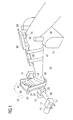
- Fig.1 is a perspective view of the device operatively attached to the leg of a patient.
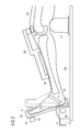
- Fig. 2 shows a cross-section of the lower leg of the patient together with the device.
- Fig. 3 shows geometrical characteristics of the inventive device.
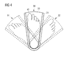
- Fig. 4 is a plantar view of the foot and the foot support platform.
- the lower leg of the patient lying on the examining table 50 is shown. It comprises thigh 40, shank 41 and ankle 43.
- the knee 44 is supported by a thigh support platform 51.
- the foot 42 is positioned into a foot support platform 30 and fixed therein by a frame 31 which may be adjusted to the size of the foot by adjustment means 33.
- straps like Velcro straps 32 may be used to secure the foot on the foot support platform.
- additional straps 64 like Velcro straps may be used to secure the knee against the thigh support platform 51.
- the thigh support platform may have additional side stops 65 to prevent lateral movement of the knee.
- the foot support platform 30 is mounted tiltable about at least two axes relative to the examining table 50.
- a tilt movement 14 of the foot support platform 30 around the first axis can be performed by rotation of a first shaft 10.
- This first shaft 10 is held by means of the bearings 11 and 12 against the examining table or an intermediate platform which may hold the whole device.
- drive means 13 are provided. These drive means may be either a drive motor like an electrical motor, preferable a DC motor or a stepper motor. Alternatively, this may be a standard adapter for a torque wrench. Of course any other means for achieving angular movement of the first shaft 10 is acceptable. This may also be achieved by a linear displacement device like a hydraulic or pneumatic cylinder together with a lever.
- a second shaft 20 For rotating 24 the foot support platform around the second axis, being approximately parallel to the axis of the tibia, a second shaft 20 is provided.
- This second shaft 20 is supported by means of one or several bearings 21 against the first shaft and is tiltable together with the first shaft around the axis of the first shaft.
- drive means 23 are provided for driving the second shaft. These drive means may be similar to the drive means described previously for the first shaft.
- a displacement test device 60 For performing the displacement measurement, a displacement test device 60 is provided. It is attached to the shank 41 by means of straps and measures the drawer shift related to the patella 45.
- Fig. 2 shows a cross-section of the lower leg of the patient with the inventive device.
- the tibia 46, femur 56 and patella 45 are shown in more detail.
- the foot 42 is shown in the natural position and in the flexed position (dashed lines).
- Fig. 3 the geometrical characteristics of the invention are shown.
- the femur axis 47 is positioned against the tibia axis 48 by a predetermined angle. Flexion of the foot is performed about a first axis by means of the first shaft 10 and rotation about the foot is performed by means of the second shaft 20.
- the displacement test device 60 asserts a force against the tibia 46 in relation to the femur 56.
- This force may be in any direction, preferably at right angles to the tibia.
- Dependent on the integrity of the anterior and posterior cruciate ligaments of the knee, applying of the displacement force results in a shift between the tibia 46 and the femur 56.
- While the foot is secured by means of the foot support platform 30, preventing the foot from moving, asserting this force 61 results in a torque on the tibia around an axis at the ankle 43.
- a torque can also be asserted by applying a second force 62 at a location different from the location where the first force 61 is applied. This also results in a torque on the tibia 46. At a position of the knee between the femur and the tibia, the torque results in a displacement force shifting the tibia and accordingly the tibia axis 48 into a displaced position 49.
- the displacement 63 can be measured by the displacement test device 60.
- a drawer shift measurement is performed.
- a force 62 is applied in an upward direction, preferably at right angle to the tibia axis.
- shift measurement is done as disclosed in the US 4,583,555 by referring to the patella 45 instead of the femur 55, as the patella is comparatively stiff attached to the femur. Accordingly, using the patella for applying force and/or for measuring the shift is advantageous.
- This shift may be in a range from 2 mm up to more than 20 mm with damaged cruciate ligaments.
- the measurement and the evaluation of the displacement can be made manually, semi-automatically, orfully automatically.
- a plotter may be attached to the displacement test device to draw a plot of the force against displacement. This may also be recorded by a computer or by any other device like a data recorder.
- Fig. 4 shows a view from bottom of the foot 42 towards the patient. A rotation about the second axis, approximately parallel to the tibia axis, is shown. From the natural position 90 the foot is either turned to the right, resulting in an outwards position 92 for the shown left foot, or turned to the left, resulting in an inwards position 91.
Landscapes
- Health & Medical Sciences (AREA)
- Life Sciences & Earth Sciences (AREA)
- Physics & Mathematics (AREA)
- Heart & Thoracic Surgery (AREA)
- Molecular Biology (AREA)
- Veterinary Medicine (AREA)
- Public Health (AREA)
- General Health & Medical Sciences (AREA)
- Biophysics (AREA)
- Pathology (AREA)
- Engineering & Computer Science (AREA)
- Biomedical Technology (AREA)
- Animal Behavior & Ethology (AREA)
- Medical Informatics (AREA)
- Surgery (AREA)
- Dentistry (AREA)
- Oral & Maxillofacial Surgery (AREA)
- Physiology (AREA)
- Orthopedic Medicine & Surgery (AREA)
- Rehabilitation Therapy (AREA)
- Rheumatology (AREA)
- Geometry (AREA)
- Physical Education & Sports Medicine (AREA)
- Measurement Of The Respiration, Hearing Ability, Form, And Blood Characteristics Of Living Organisms (AREA)
Priority Applications (3)
| Application Number | Priority Date | Filing Date | Title |
|---|---|---|---|
| EP08154617A EP2110077B1 (de) | 2008-04-16 | 2008-04-16 | Vorrichtung und Verfahren zur Messung der Belastung des Kreuzbandes des Knies |
| US12/393,777 US7976482B2 (en) | 2008-04-16 | 2009-02-26 | Device and method for knee ligament strain measurement |
| PCT/EP2009/054457 WO2009127654A1 (en) | 2008-04-16 | 2009-04-15 | Device and method for knee ligament strain measurement |
Applications Claiming Priority (1)
| Application Number | Priority Date | Filing Date | Title |
|---|---|---|---|
| EP08154617A EP2110077B1 (de) | 2008-04-16 | 2008-04-16 | Vorrichtung und Verfahren zur Messung der Belastung des Kreuzbandes des Knies |
Publications (2)
| Publication Number | Publication Date |
|---|---|
| EP2110077A1 true EP2110077A1 (de) | 2009-10-21 |
| EP2110077B1 EP2110077B1 (de) | 2012-06-27 |
Family
ID=39713963
Family Applications (1)
| Application Number | Title | Priority Date | Filing Date |
|---|---|---|---|
| EP08154617A Not-in-force EP2110077B1 (de) | 2008-04-16 | 2008-04-16 | Vorrichtung und Verfahren zur Messung der Belastung des Kreuzbandes des Knies |
Country Status (3)
| Country | Link |
|---|---|
| US (1) | US7976482B2 (de) |
| EP (1) | EP2110077B1 (de) |
| WO (1) | WO2009127654A1 (de) |
Cited By (10)
| Publication number | Priority date | Publication date | Assignee | Title |
|---|---|---|---|---|
| WO2011048289A1 (fr) * | 2009-10-22 | 2011-04-28 | Genourob | Perfectionnements au dispositif de détection et de suivi d'une lésion totale ou partielle du ligament croisé antérieur du genou, par comparaison entre les deux membres |
| CN103040470A (zh) * | 2012-12-26 | 2013-04-17 | 复旦大学附属华山医院 | 一种脚踝关节测试平台 |
| CN103976745A (zh) * | 2014-04-30 | 2014-08-13 | 河南科技大学 | 一种足背动脉辅助采血固定装置 |
| EP2371282A4 (de) * | 2009-08-18 | 2014-08-13 | Fundacion Garcia Cugat | Vorrichtung zur messung von drehinstabilitäten des knies |
| EP2801319A1 (de) * | 2013-05-06 | 2014-11-12 | IT-V Medizintechnik GmbH | Vorrichtung zur Lagerung der unteren Extremitäten eines Patienten während der radiologischen Diagnostik bzw. Behandlung |
| CN104490396A (zh) * | 2013-10-24 | 2015-04-08 | 山东大学齐鲁医院(青岛) | 一种髋关节扭矩测量系统 |
| CN104490396B (zh) * | 2013-10-24 | 2017-01-04 | 山东大学齐鲁医院(青岛) | 一种髋关节扭矩测量系统 |
| CN110575143A (zh) * | 2019-09-26 | 2019-12-17 | 北京大学第三医院(北京大学第三临床医学院) | 膝关节松弛度测量仪 |
| EP2578150B1 (de) * | 2010-06-04 | 2020-07-29 | Fjr, Sgps, S.A. | Vorrichtung zum messen der knieschlaffheit und deren verwendung |
| US10849551B2 (en) | 2016-06-24 | 2020-12-01 | Surgical Sensors Bvba | Integrated ligament strain measurement |
Families Citing this family (21)
| Publication number | Priority date | Publication date | Assignee | Title |
|---|---|---|---|---|
| US7753862B2 (en) * | 2005-07-13 | 2010-07-13 | Thomas P. Branch | Apparatus and method for evaluating ligaments |
| US9289157B2 (en) | 2010-08-13 | 2016-03-22 | ERML Inc. | Robotic knee testing device, subjective patient input device and methods for using same |
| WO2012021726A1 (en) * | 2010-08-13 | 2012-02-16 | Ermi, Inc. | Robotic knee testing device, subjective patient input device and methods for using same |
| US9408771B2 (en) | 2010-08-27 | 2016-08-09 | Ermi, Inc. | Bladder driven linear cylinder and associated devices driven thereby |
| US20120142507A1 (en) * | 2010-12-06 | 2012-06-07 | Belin George E | Exercise Device with Knee Rest |
| JP5884221B2 (ja) * | 2011-10-03 | 2016-03-15 | 国立大学法人神戸大学 | 足首インピーダンスの測定装置 |
| US9788792B2 (en) * | 2011-10-26 | 2017-10-17 | The United States of America, as represented by Department of Veterans Affairs, Office of General Counsel, Professional Staff Group IV(024) | System for screening skin condition for tissue damage |
| US9301688B2 (en) * | 2011-10-26 | 2016-04-05 | The United States of America, as Represented by Dept. of Veterans Affairs | System for screening the skin condition of the plantar surface of the feet |
| KR101337361B1 (ko) * | 2012-03-29 | 2013-12-06 | 김재화 | 무릎관절 회전각 측정장치 및 그를 이용한 측정 방법 |
| EP2895052B1 (de) * | 2012-09-17 | 2021-07-07 | RoboDiagnostics LLC | Robotische knietest-vorrichtung (rkt) mit entkoppelter treiberfähigkeit sowie systeme und verfahren dafür |
| US9839389B2 (en) * | 2014-04-23 | 2017-12-12 | Rosalind Franklin University Of Medicine And Science | Foot-strength test device and methods for use |
| US9682002B2 (en) | 2014-06-25 | 2017-06-20 | George E. Belin | Exercise device assembly |
| US11484254B2 (en) * | 2015-11-20 | 2022-11-01 | RoboDiagnostics LLC | Floating patella sensor, knee stabilizer with same and robotic knee testing apparatus with same |
| KR101888760B1 (ko) * | 2016-11-23 | 2018-08-16 | 동서대학교산학협력단 | 종아리 스트레칭 보드 동작방법 |
| CN107753244B (zh) * | 2017-11-25 | 2019-12-17 | 福州大学 | 一种基于章动原理的混联式踝关节康复机运动控制方法 |
| CN108836781B (zh) * | 2018-06-27 | 2020-04-24 | 奉节县仁爱医院有限责任公司 | 一种医疗膝盖关节炎自动理疗仪及其康复理疗方法 |
| CN109907774A (zh) * | 2019-03-04 | 2019-06-21 | 广州中医药大学第一附属医院 | 固定下肢体位的装置 |
| CN110236554B (zh) * | 2019-07-19 | 2020-07-28 | 张晋 | 一种胫骨前后移动测量装置 |
| CN111700622B (zh) * | 2020-07-03 | 2021-02-02 | 四川大学华西医院 | 腿部抬升角度检测装置 |
| CN112999052B (zh) * | 2021-04-07 | 2023-01-03 | 辽东学院 | 一种运动员膝关节损伤辅助康复设备及其使用方法 |
| US20250072790A1 (en) * | 2023-08-30 | 2025-03-06 | Globus Medical, Inc. | Ligament balancing tool and method for same |
Citations (9)
| Publication number | Priority date | Publication date | Assignee | Title |
|---|---|---|---|---|
| US597869A (en) * | 1898-01-25 | Manufacture of chrome-steel alloy | ||
| US4583555A (en) | 1983-01-03 | 1986-04-22 | Medmetric Corporation | Knee ligament testing system |
| WO1987005789A1 (en) * | 1986-03-27 | 1987-10-08 | Gregory James Roger | Measurement of laxity of anterior cruciate ligament |
| US4733859A (en) * | 1986-10-09 | 1988-03-29 | Bio-Mechanisms, Inc. | Exercise apparatus |
| EP0496528A1 (de) * | 1991-01-22 | 1992-07-29 | Compagnie Generale De Materiel Orthopedique | Übungsgerät zur passiven Bewegung |
| WO1993002621A1 (en) * | 1991-08-01 | 1993-02-18 | Drexel University | Joint flexibility determining apparatus and method |
| EP0568148A1 (de) * | 1992-04-21 | 1993-11-03 | Gatso Special Products B.V. | Vorrichtung zur Prüfung eines Gelenks |
| EP1364636A1 (de) * | 2002-05-08 | 2003-11-26 | Mamoru Mitsuishi | Repositionsvorrichtung |
| WO2005104945A2 (en) * | 2004-05-04 | 2005-11-10 | Imperial Innovations Limited | Measurement of laxity of human joints |
Family Cites Families (2)
| Publication number | Priority date | Publication date | Assignee | Title |
|---|---|---|---|---|
| US5957869A (en) * | 1995-08-21 | 1999-09-28 | Caruso; Steven A. | Apparatus and method for measuring anatomical orthopedic joint laxity |
| CA2705241A1 (en) * | 2007-11-09 | 2009-05-22 | Ermi, Inc. | Multi-section limb and ligament evaluation apparatus and associated methods for using same |
-
2008
- 2008-04-16 EP EP08154617A patent/EP2110077B1/de not_active Not-in-force
-
2009
- 2009-02-26 US US12/393,777 patent/US7976482B2/en not_active Expired - Fee Related
- 2009-04-15 WO PCT/EP2009/054457 patent/WO2009127654A1/en not_active Ceased
Patent Citations (10)
| Publication number | Priority date | Publication date | Assignee | Title |
|---|---|---|---|---|
| US597869A (en) * | 1898-01-25 | Manufacture of chrome-steel alloy | ||
| US4583555A (en) | 1983-01-03 | 1986-04-22 | Medmetric Corporation | Knee ligament testing system |
| WO1987005789A1 (en) * | 1986-03-27 | 1987-10-08 | Gregory James Roger | Measurement of laxity of anterior cruciate ligament |
| US4913163A (en) | 1986-03-27 | 1990-04-03 | Roger Gregory J | Measurement of laxity of anterior cruciate ligament |
| US4733859A (en) * | 1986-10-09 | 1988-03-29 | Bio-Mechanisms, Inc. | Exercise apparatus |
| EP0496528A1 (de) * | 1991-01-22 | 1992-07-29 | Compagnie Generale De Materiel Orthopedique | Übungsgerät zur passiven Bewegung |
| WO1993002621A1 (en) * | 1991-08-01 | 1993-02-18 | Drexel University | Joint flexibility determining apparatus and method |
| EP0568148A1 (de) * | 1992-04-21 | 1993-11-03 | Gatso Special Products B.V. | Vorrichtung zur Prüfung eines Gelenks |
| EP1364636A1 (de) * | 2002-05-08 | 2003-11-26 | Mamoru Mitsuishi | Repositionsvorrichtung |
| WO2005104945A2 (en) * | 2004-05-04 | 2005-11-10 | Imperial Innovations Limited | Measurement of laxity of human joints |
Cited By (11)
| Publication number | Priority date | Publication date | Assignee | Title |
|---|---|---|---|---|
| EP2371282A4 (de) * | 2009-08-18 | 2014-08-13 | Fundacion Garcia Cugat | Vorrichtung zur messung von drehinstabilitäten des knies |
| WO2011048289A1 (fr) * | 2009-10-22 | 2011-04-28 | Genourob | Perfectionnements au dispositif de détection et de suivi d'une lésion totale ou partielle du ligament croisé antérieur du genou, par comparaison entre les deux membres |
| FR2951628A1 (fr) * | 2009-10-22 | 2011-04-29 | Genourob | Perfectionnements du dispositif de detection et de suivi d'une lesion totale ou partielle du ligament croise anterieur du genou, par comparaison entre les deux membres |
| EP2578150B1 (de) * | 2010-06-04 | 2020-07-29 | Fjr, Sgps, S.A. | Vorrichtung zum messen der knieschlaffheit und deren verwendung |
| CN103040470A (zh) * | 2012-12-26 | 2013-04-17 | 复旦大学附属华山医院 | 一种脚踝关节测试平台 |
| EP2801319A1 (de) * | 2013-05-06 | 2014-11-12 | IT-V Medizintechnik GmbH | Vorrichtung zur Lagerung der unteren Extremitäten eines Patienten während der radiologischen Diagnostik bzw. Behandlung |
| CN104490396A (zh) * | 2013-10-24 | 2015-04-08 | 山东大学齐鲁医院(青岛) | 一种髋关节扭矩测量系统 |
| CN104490396B (zh) * | 2013-10-24 | 2017-01-04 | 山东大学齐鲁医院(青岛) | 一种髋关节扭矩测量系统 |
| CN103976745A (zh) * | 2014-04-30 | 2014-08-13 | 河南科技大学 | 一种足背动脉辅助采血固定装置 |
| US10849551B2 (en) | 2016-06-24 | 2020-12-01 | Surgical Sensors Bvba | Integrated ligament strain measurement |
| CN110575143A (zh) * | 2019-09-26 | 2019-12-17 | 北京大学第三医院(北京大学第三临床医学院) | 膝关节松弛度测量仪 |
Also Published As
| Publication number | Publication date |
|---|---|
| US7976482B2 (en) | 2011-07-12 |
| WO2009127654A1 (en) | 2009-10-22 |
| US20090264797A1 (en) | 2009-10-22 |
| EP2110077B1 (de) | 2012-06-27 |
Similar Documents
| Publication | Publication Date | Title |
|---|---|---|
| EP2110077B1 (de) | Vorrichtung und Verfahren zur Messung der Belastung des Kreuzbandes des Knies | |
| US8840570B2 (en) | Multi-section limb and ligament evaluation apparatus and associated methods for using same | |
| US10575773B2 (en) | Apparatus and method for evaluating ligaments | |
| US4969471A (en) | Knee ligament testing device and method of use | |
| US10750979B2 (en) | Apparatus and method for determining 3D load displacement response of a joint | |
| US9451918B2 (en) | Device for measuring knee laxity | |
| US11660044B2 (en) | Apparatus and method for assessing laxity of a joint | |
| Hubbard et al. | Reliability of intratester and intertester measurements derived from an instrumented ankle arthrometer. | |
| EP3251589B1 (de) | Vorrichtung zum testen eines robotischen knies und patient und vorrichtungseinstellverfahren | |
| EP0293372B1 (de) | Gerät zur unblutigen tauglichkeitsprüfung des kniegelenkes am lebenden menschen | |
| US20180333096A1 (en) | Thigh Immobilizer for a Robotic Knee Testing Apparatus | |
| US5402800A (en) | Ankle laxity measurement system | |
| WO2023278096A1 (en) | Multi-axial joint laxity testing apparatus and method | |
| WO2020096955A1 (en) | Multi-axial joint laxity testing apparatus and method | |
| US20230181098A1 (en) | Apparatus and method for assessing laxity of a joint | |
| Rastegar et al. | An apparatus for measuring the load-displacement and load-dependent kinematic characteristics of articulating joints—application to the human ankle joint | |
| US5462068A (en) | Wrist fixation device for elbow stress examination | |
| JP2013502253A (ja) | 膝の回動不安定性を測定する測定デバイス | |
| US11737711B2 (en) | Residual joint displacement monitoring and compensation | |
| DE3636843A1 (de) | Messgeraet zur bestimmung vorderer und hinterer schubladen am menschlichen kniegelenk in verschiedenen rotationsstellungen des unterschenkels und in verschiedenen beugestellungen | |
| Kendoff et al. | Accuracy of Translation and Rotation Measurements in Navigated ACL Reconstruction | |
| Lew | D. zyxwvutsrqpon |
Legal Events
| Date | Code | Title | Description |
|---|---|---|---|
| PUAI | Public reference made under article 153(3) epc to a published international application that has entered the european phase |
Free format text: ORIGINAL CODE: 0009012 |
|
| AK | Designated contracting states |
Kind code of ref document: A1 Designated state(s): AT BE BG CH CY CZ DE DK EE ES FI FR GB GR HR HU IE IS IT LI LT LU LV MC MT NL NO PL PT RO SE SI SK TR |
|
| AX | Request for extension of the european patent |
Extension state: AL BA MK RS |
|
| 17P | Request for examination filed |
Effective date: 20091112 |
|
| 17Q | First examination report despatched |
Effective date: 20091211 |
|
| AKX | Designation fees paid |
Designated state(s): AT BE BG CH CY CZ DE DK EE ES FI FR GB GR HR HU IE IS IT LI LT LU LV MC MT NL NO PL PT RO SE SI SK TR |
|
| GRAP | Despatch of communication of intention to grant a patent |
Free format text: ORIGINAL CODE: EPIDOSNIGR1 |
|
| GRAS | Grant fee paid |
Free format text: ORIGINAL CODE: EPIDOSNIGR3 |
|
| GRAA | (expected) grant |
Free format text: ORIGINAL CODE: 0009210 |
|
| AK | Designated contracting states |
Kind code of ref document: B1 Designated state(s): AT BE BG CH CY CZ DE DK EE ES FI FR GB GR HR HU IE IS IT LI LT LU LV MC MT NL NO PL PT RO SE SI SK TR |
|
| REG | Reference to a national code |
Ref country code: GB Ref legal event code: FG4D |
|
| REG | Reference to a national code |
Ref country code: CH Ref legal event code: EP |
|
| REG | Reference to a national code |
Ref country code: AT Ref legal event code: REF Ref document number: 563702 Country of ref document: AT Kind code of ref document: T Effective date: 20120715 |
|
| REG | Reference to a national code |
Ref country code: IE Ref legal event code: FG4D |
|
| REG | Reference to a national code |
Ref country code: DE Ref legal event code: R096 Ref document number: 602008016679 Country of ref document: DE Effective date: 20120830 |
|
| PG25 | Lapsed in a contracting state [announced via postgrant information from national office to epo] |
Ref country code: FI Free format text: LAPSE BECAUSE OF FAILURE TO SUBMIT A TRANSLATION OF THE DESCRIPTION OR TO PAY THE FEE WITHIN THE PRESCRIBED TIME-LIMIT Effective date: 20120627 Ref country code: NO Free format text: LAPSE BECAUSE OF FAILURE TO SUBMIT A TRANSLATION OF THE DESCRIPTION OR TO PAY THE FEE WITHIN THE PRESCRIBED TIME-LIMIT Effective date: 20120927 Ref country code: SE Free format text: LAPSE BECAUSE OF FAILURE TO SUBMIT A TRANSLATION OF THE DESCRIPTION OR TO PAY THE FEE WITHIN THE PRESCRIBED TIME-LIMIT Effective date: 20120627 Ref country code: LT Free format text: LAPSE BECAUSE OF FAILURE TO SUBMIT A TRANSLATION OF THE DESCRIPTION OR TO PAY THE FEE WITHIN THE PRESCRIBED TIME-LIMIT Effective date: 20120627 |
|
| REG | Reference to a national code |
Ref country code: NL Ref legal event code: VDEP Effective date: 20120627 |
|
| REG | Reference to a national code |
Ref country code: AT Ref legal event code: MK05 Ref document number: 563702 Country of ref document: AT Kind code of ref document: T Effective date: 20120627 |
|
| REG | Reference to a national code |
Ref country code: LT Ref legal event code: MG4D Effective date: 20120627 |
|
| PG25 | Lapsed in a contracting state [announced via postgrant information from national office to epo] |
Ref country code: SI Free format text: LAPSE BECAUSE OF FAILURE TO SUBMIT A TRANSLATION OF THE DESCRIPTION OR TO PAY THE FEE WITHIN THE PRESCRIBED TIME-LIMIT Effective date: 20120627 Ref country code: HR Free format text: LAPSE BECAUSE OF FAILURE TO SUBMIT A TRANSLATION OF THE DESCRIPTION OR TO PAY THE FEE WITHIN THE PRESCRIBED TIME-LIMIT Effective date: 20120627 Ref country code: GR Free format text: LAPSE BECAUSE OF FAILURE TO SUBMIT A TRANSLATION OF THE DESCRIPTION OR TO PAY THE FEE WITHIN THE PRESCRIBED TIME-LIMIT Effective date: 20120928 Ref country code: LV Free format text: LAPSE BECAUSE OF FAILURE TO SUBMIT A TRANSLATION OF THE DESCRIPTION OR TO PAY THE FEE WITHIN THE PRESCRIBED TIME-LIMIT Effective date: 20120627 |
|
| PG25 | Lapsed in a contracting state [announced via postgrant information from national office to epo] |
Ref country code: CZ Free format text: LAPSE BECAUSE OF FAILURE TO SUBMIT A TRANSLATION OF THE DESCRIPTION OR TO PAY THE FEE WITHIN THE PRESCRIBED TIME-LIMIT Effective date: 20120627 Ref country code: RO Free format text: LAPSE BECAUSE OF FAILURE TO SUBMIT A TRANSLATION OF THE DESCRIPTION OR TO PAY THE FEE WITHIN THE PRESCRIBED TIME-LIMIT Effective date: 20120627 Ref country code: CY Free format text: LAPSE BECAUSE OF FAILURE TO SUBMIT A TRANSLATION OF THE DESCRIPTION OR TO PAY THE FEE WITHIN THE PRESCRIBED TIME-LIMIT Effective date: 20120627 Ref country code: AT Free format text: LAPSE BECAUSE OF FAILURE TO SUBMIT A TRANSLATION OF THE DESCRIPTION OR TO PAY THE FEE WITHIN THE PRESCRIBED TIME-LIMIT Effective date: 20120627 Ref country code: SK Free format text: LAPSE BECAUSE OF FAILURE TO SUBMIT A TRANSLATION OF THE DESCRIPTION OR TO PAY THE FEE WITHIN THE PRESCRIBED TIME-LIMIT Effective date: 20120627 Ref country code: EE Free format text: LAPSE BECAUSE OF FAILURE TO SUBMIT A TRANSLATION OF THE DESCRIPTION OR TO PAY THE FEE WITHIN THE PRESCRIBED TIME-LIMIT Effective date: 20120627 Ref country code: IS Free format text: LAPSE BECAUSE OF FAILURE TO SUBMIT A TRANSLATION OF THE DESCRIPTION OR TO PAY THE FEE WITHIN THE PRESCRIBED TIME-LIMIT Effective date: 20121027 Ref country code: BE Free format text: LAPSE BECAUSE OF FAILURE TO SUBMIT A TRANSLATION OF THE DESCRIPTION OR TO PAY THE FEE WITHIN THE PRESCRIBED TIME-LIMIT Effective date: 20120627 |
|
| PG25 | Lapsed in a contracting state [announced via postgrant information from national office to epo] |
Ref country code: PT Free format text: LAPSE BECAUSE OF FAILURE TO SUBMIT A TRANSLATION OF THE DESCRIPTION OR TO PAY THE FEE WITHIN THE PRESCRIBED TIME-LIMIT Effective date: 20121029 Ref country code: PL Free format text: LAPSE BECAUSE OF FAILURE TO SUBMIT A TRANSLATION OF THE DESCRIPTION OR TO PAY THE FEE WITHIN THE PRESCRIBED TIME-LIMIT Effective date: 20120627 Ref country code: IT Free format text: LAPSE BECAUSE OF FAILURE TO SUBMIT A TRANSLATION OF THE DESCRIPTION OR TO PAY THE FEE WITHIN THE PRESCRIBED TIME-LIMIT Effective date: 20120627 |
|
| PG25 | Lapsed in a contracting state [announced via postgrant information from national office to epo] |
Ref country code: NL Free format text: LAPSE BECAUSE OF FAILURE TO SUBMIT A TRANSLATION OF THE DESCRIPTION OR TO PAY THE FEE WITHIN THE PRESCRIBED TIME-LIMIT Effective date: 20120627 |
|
| PG25 | Lapsed in a contracting state [announced via postgrant information from national office to epo] |
Ref country code: DK Free format text: LAPSE BECAUSE OF FAILURE TO SUBMIT A TRANSLATION OF THE DESCRIPTION OR TO PAY THE FEE WITHIN THE PRESCRIBED TIME-LIMIT Effective date: 20120627 Ref country code: ES Free format text: LAPSE BECAUSE OF FAILURE TO SUBMIT A TRANSLATION OF THE DESCRIPTION OR TO PAY THE FEE WITHIN THE PRESCRIBED TIME-LIMIT Effective date: 20121008 |
|
| PLBE | No opposition filed within time limit |
Free format text: ORIGINAL CODE: 0009261 |
|
| STAA | Information on the status of an ep patent application or granted ep patent |
Free format text: STATUS: NO OPPOSITION FILED WITHIN TIME LIMIT |
|
| 26N | No opposition filed |
Effective date: 20130328 |
|
| REG | Reference to a national code |
Ref country code: DE Ref legal event code: R097 Ref document number: 602008016679 Country of ref document: DE Effective date: 20130328 |
|
| PG25 | Lapsed in a contracting state [announced via postgrant information from national office to epo] |
Ref country code: BG Free format text: LAPSE BECAUSE OF FAILURE TO SUBMIT A TRANSLATION OF THE DESCRIPTION OR TO PAY THE FEE WITHIN THE PRESCRIBED TIME-LIMIT Effective date: 20120927 |
|
| PG25 | Lapsed in a contracting state [announced via postgrant information from national office to epo] |
Ref country code: MC Free format text: LAPSE BECAUSE OF FAILURE TO SUBMIT A TRANSLATION OF THE DESCRIPTION OR TO PAY THE FEE WITHIN THE PRESCRIBED TIME-LIMIT Effective date: 20120627 |
|
| REG | Reference to a national code |
Ref country code: CH Ref legal event code: PL |
|
| GBPC | Gb: european patent ceased through non-payment of renewal fee |
Effective date: 20130416 |
|
| REG | Reference to a national code |
Ref country code: IE Ref legal event code: MM4A |
|
| PG25 | Lapsed in a contracting state [announced via postgrant information from national office to epo] |
Ref country code: CH Free format text: LAPSE BECAUSE OF NON-PAYMENT OF DUE FEES Effective date: 20130430 Ref country code: GB Free format text: LAPSE BECAUSE OF NON-PAYMENT OF DUE FEES Effective date: 20130416 Ref country code: LI Free format text: LAPSE BECAUSE OF NON-PAYMENT OF DUE FEES Effective date: 20130430 |
|
| REG | Reference to a national code |
Ref country code: FR Ref legal event code: ST Effective date: 20131231 |
|
| PG25 | Lapsed in a contracting state [announced via postgrant information from national office to epo] |
Ref country code: FR Free format text: LAPSE BECAUSE OF NON-PAYMENT OF DUE FEES Effective date: 20130430 |
|
| PG25 | Lapsed in a contracting state [announced via postgrant information from national office to epo] |
Ref country code: IE Free format text: LAPSE BECAUSE OF NON-PAYMENT OF DUE FEES Effective date: 20130416 |
|
| PG25 | Lapsed in a contracting state [announced via postgrant information from national office to epo] |
Ref country code: MT Free format text: LAPSE BECAUSE OF FAILURE TO SUBMIT A TRANSLATION OF THE DESCRIPTION OR TO PAY THE FEE WITHIN THE PRESCRIBED TIME-LIMIT Effective date: 20120627 |
|
| PG25 | Lapsed in a contracting state [announced via postgrant information from national office to epo] |
Ref country code: TR Free format text: LAPSE BECAUSE OF FAILURE TO SUBMIT A TRANSLATION OF THE DESCRIPTION OR TO PAY THE FEE WITHIN THE PRESCRIBED TIME-LIMIT Effective date: 20120627 |
|
| PG25 | Lapsed in a contracting state [announced via postgrant information from national office to epo] |
Ref country code: LU Free format text: LAPSE BECAUSE OF NON-PAYMENT OF DUE FEES Effective date: 20130416 Ref country code: HU Free format text: LAPSE BECAUSE OF FAILURE TO SUBMIT A TRANSLATION OF THE DESCRIPTION OR TO PAY THE FEE WITHIN THE PRESCRIBED TIME-LIMIT; INVALID AB INITIO Effective date: 20080416 |
|
| PGFP | Annual fee paid to national office [announced via postgrant information from national office to epo] |
Ref country code: DE Payment date: 20210428 Year of fee payment: 14 |
|
| REG | Reference to a national code |
Ref country code: DE Ref legal event code: R119 Ref document number: 602008016679 Country of ref document: DE |
|
| PG25 | Lapsed in a contracting state [announced via postgrant information from national office to epo] |
Ref country code: DE Free format text: LAPSE BECAUSE OF NON-PAYMENT OF DUE FEES Effective date: 20221103 |