EP2110176B1 - Wassersparer mit zwei Durchflussmengen - Google Patents
Wassersparer mit zwei Durchflussmengen Download PDFInfo
- Publication number
- EP2110176B1 EP2110176B1 EP08305108A EP08305108A EP2110176B1 EP 2110176 B1 EP2110176 B1 EP 2110176B1 EP 08305108 A EP08305108 A EP 08305108A EP 08305108 A EP08305108 A EP 08305108A EP 2110176 B1 EP2110176 B1 EP 2110176B1
- Authority
- EP
- European Patent Office
- Prior art keywords
- flow
- economiser
- closing
- guide
- translation
- Prior art date
- Legal status (The legal status is an assumption and is not a legal conclusion. Google has not performed a legal analysis and makes no representation as to the accuracy of the status listed.)
- Active
Links
Images
Classifications
-
- B—PERFORMING OPERATIONS; TRANSPORTING
- B05—SPRAYING OR ATOMISING IN GENERAL; APPLYING FLUENT MATERIALS TO SURFACES, IN GENERAL
- B05B—SPRAYING APPARATUS; ATOMISING APPARATUS; NOZZLES
- B05B1/00—Nozzles, spray heads or other outlets, with or without auxiliary devices such as valves, heating means
- B05B1/30—Nozzles, spray heads or other outlets, with or without auxiliary devices such as valves, heating means designed to control volume of flow, e.g. with adjustable passages
- B05B1/3026—Gate valves; Sliding valves; Cocks
-
- E—FIXED CONSTRUCTIONS
- E03—WATER SUPPLY; SEWERAGE
- E03C—DOMESTIC PLUMBING INSTALLATIONS FOR FRESH WATER OR WASTE WATER; SINKS
- E03C1/00—Domestic plumbing installations for fresh water or waste water; Sinks
- E03C1/02—Plumbing installations for fresh water
- E03C1/04—Water-basin installations specially adapted to wash-basins or baths
- E03C1/0408—Water installations especially for showers
- E03C1/0409—Shower handles
-
- E—FIXED CONSTRUCTIONS
- E03—WATER SUPPLY; SEWERAGE
- E03C—DOMESTIC PLUMBING INSTALLATIONS FOR FRESH WATER OR WASTE WATER; SINKS
- E03C1/00—Domestic plumbing installations for fresh water or waste water; Sinks
- E03C1/02—Plumbing installations for fresh water
- E03C2001/026—Plumbing installations for fresh water with flow restricting devices
Definitions
- the present invention relates to a water-saving device for reducing the flow of water, said economizer fitting on faucets, especially for showers, between the end of the flexible hose of the shower and the apple of shower. It also relates to a shower head incorporating said economizer.
- the economizers which are also called flow reduction devices, consist of an inlet and a fluid outlet, and means for adjusting the output fluid flow. This is the case in patents US 6213154 , DE 3318726 , EP 0489296 .
- the patent US 6213154 discloses a flow regulator disposed upstream of a valve, said regulator comprising a flow tube and a flow reduction member, said reduction member having its axis perpendicular to the flow tube.
- the reduction piece comprises a cylindrical shape provided with a flat part and is rotatably mounted along its axis on the flow tube, the rotation of the part making it possible to modify the orientation of the flat part, which modifies the passage section. water in the flow tube, and thus allows to vary the flow of water.
- the patent DE 3318726 discloses a regulating valve for showers.
- the means for reducing the flow rate consist of a sphere mounted in rotation along an axis perpendicular to a flow tube.
- the sphere is provided with channels, the rotation of the sphere in a first position for positioning a first channel in the axis of the flow tube to provide a first output flow, and the rotation of the sphere in a second position allowing positioning a plurality of channels in the axis of the flow tube to provide a second output flow.
- the patent EP 0489296 discloses a valve provided with a flow control device.
- the device consists of a spherical part comprising an orifice of diameter corresponding to the diameter of a flow tube, the rotating the spherical piece along an axis perpendicular to the axis of the flow tube allowing either the passage of water or the total closure of said flow tube.
- the device also comprises a piece slidably mounted on the sphere along said axis perpendicular to the flow axis. The piece has a width corresponding to the diameter of the flow tube, the translation of said piece into the sphere for partially closing the orifice of the sphere to partially close the flow tube and thus reduce the output flow.
- the water saver according to the invention implements a new design of the flow reduction means.
- This design has the advantage of reducing the manufacturing cost of the economizer, and simplifying the handling of the control means in use. It also has the advantage of reducing the bulk of said reduction means, which makes it possible to minimize the size of the economizer, in particular when it is adapted to the end of a shower head, which is manipulated by the user.
- the invention relates to a water-saving device for reducing the flow rate of water, said economizer consisting of a body which comprises a water inlet orifice and a water outlet orifice, and flow control means, the inlet port and the outlet port being defined along the same flow axis.
- the economizer is remarkable in that the flow control means comprise an intermediate chamber between the inlet port and the outlet port, and a flow reduction part which slides in the next chamber.
- said reduction member comprising at least two closure zones defined along the translation axis of the reduction piece, said translation of the reduction piece allowing complete positioning of the reduction piece; one of the shutter areas in the flow axis to reduce the flow of water according to different values.
- the invention also relates to a shower head incorporating the water saver directly into the body of said shower head.
- the water saver 1 has the function of allowing the reduction of the water flow at the outlet of a faucet, especially at the outlet of a shower head; the closure of the water flow is preferably provided directly on said valve and not on the economizer, which helps to simplify the design of said economizer 1.
- the economizer 1 is for example positioned between the hose of the shower and the entrance of the shower head, within easy reach of the user, reducing the size of the economizer facilitating the handling of the shower head, without discomfort for the user, despite the presence of said saver at the end of the showerhead.
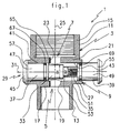
- the economiser 1 consists of a body 3 which comprises a water inlet orifice 5 and a water outlet orifice 7, and flow control means 7, said adjustment means 9 being arranged on the body 3, between the inlet orifice 3 and the outlet orifice 5.
- the outer casing 11 of the body 3 is preferably of tubular shape, similar to that of a flexible pipe or that of the end of a shower head.
- the body 3 comprises a male tubular portion 13 and a female tubular portion 15.
- the male part 13 is threaded, and it is for example intended to receive the female part of a shower hose.
- the male part 13 is bored, the bottom 17 of the bore comprising an orifice 19 which constitutes said inlet orifice 5 through which the water enters the adjustment means 9 with an inlet flow.
- the female part 15 is threaded, and it is for example intended to receive the male end of a shower head.
- the female part 15 is also bored, the bottom 21 of the bore comprising an orifice 23 which constitutes said outlet orifice 7 through which the water leaves out of the adjustment means 9 with a reduced output flow rate with respect to the flow rate. Entrance.
- the body 3 thus constitutes a flow tube whose inlet orifice 5 and outlet orifice 7 are defined along the same flow axis 25.
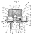
- the flow control means 9 consist of an intermediate chamber 27 arranged between the inlet orifice 5 and the outlet orifice 7, and a flow reduction piece 29. This reduction piece 29 slides in the intermediate chamber 27 along an axis of translation 31 perpendicular to the flow axis 25.
- the reduction piece 29 comprises at least two closure zones 33, 35. These closure zones 33, 35 are defined along the axis of translation 31 of said reduction piece 29.
- the translation of the reduction piece 29 allows positioning one of the closure zones 33, 35 in the flow axis 25 to reduce the water flow, each shutter zone allowing the flow rate to be adjusted to a different value from that of the other shutter zones.
- the reduction piece 29 comprises two closing zones 33, 35, the translation of this reduction piece 29 in a direction making it possible to position the first closure zone 33 in the flow axis 25, and its next translation the other direction for positioning the second closure zone 35 in said flow axis 25.
- the reduction piece 29 is preferably of shape cylindrical. It has a first closure zone 33 having a diameter D 1 for which corresponds a first output flow rate value. It then has a second closure zone 35 having a diameter D 2 for which a second output flow rate value corresponds. These two output flows are proportional to the input flow rate that can optionally be adjusted by the user according to the position of adaptation of the economizer 1 on the valve.
- the reduction piece 29 comprises at least one guide zone 37, 39 in translation in the intermediate chamber 27.
- This guide zone 37, 39 fits into at least one receiving zone 41, 43 inside the chamber intermediate 27.
- the reduction piece 29 comprises a guide piece 45 constituting two guide zones 37, 39.
- the guide piece consists of two guide heads 47, 49 which each comprise an extension 51, 53, said extensions being arranged in screws to screw inside the intermediate chamber 27, one 51 constituting the male part of the guide piece 45 and the other 53 the female part, said male and female parts allowing the coupling of the two guide heads 47 , 49 to form said guide piece 45.
- the guide heads 47, 49 each comprise at their end a stopper 55, 57. These stops 55, 57 allow the translation stop in translation of the guide piece 45 in both directions, along the axis of translation 31 They consist, for example, of a slight shoulder or bead at the end of each head 47, 49.
- At least one of the extensions of one of the guide heads 47 is arranged to constitute the two closing zones 33, 35.
- the guide head 47 comprises two shoulders so as to form three successive cylindrical parts, the first part constituting the guiding zone 37 in the intermediate chamber 9, the second and third parts forming the extension 53, said second portion constituting the first closure zone 33 of diameter D 1 and said third portion constituting the second closure zone 35 of diameter D 2 .
- This third part is also provided with the female part allowing the coupling with the male part of the second guide head 49.
- the guide head 49 comprises a shoulder so as to form two successive cylindrical parts, the first part constituting the guiding zone 39 and the second part constituting the male part coupling with the female part on the other guiding head 47.
- the reduction piece 29 comprises a shutter piece 59 provided with the two shutter zones 33, 35.
- This shutter piece 59 is arranged to fit on the guide piece 45, at the extensions 51, 53 on the two guide heads 47, 49.
- the closure piece 59 is constituted by a spacer which has a shoulder so as to form two successive cylindrical portions, the first cylindrical portion 61 having a diameter D1 corresponding to the first closure zone 33, and the second cylindrical portion 63 having a diameter D2 corresponding to the second closure zone 35. At least one of the guide heads 47 is arranged to receive the closure piece 59.
- the guide head 47 has a shoulder so as to form two successive cylindrical portions, the first portion constituting the guide zone 37, and the second portion constituting the extension 53 which receives the closure piece 59.
- the end of this second part is provided with the female part coupling on the male part of the second guide head 49.
- the guide head 49 also has a shoulder so as to form two successive cylindrical parts, the first part constituting the zone of guide 39 and the second part constituting the male part coupling on the female part of the other guide head 47.
- the intermediate chamber 9 comprises two receiving zones 41, 43 of the guide piece 45.
- These receiving zones 41, 43 are constituted by the cylindrical ends of said intermediate chamber 27, said cylindrical ends having a diameter adapted to that of the first parts of both guide heads 47,49.
- the design of the guide piece 45, and thus that of the coupled guide heads 47, 49, is arranged and dimensioned so that it can slide in the receiving zones 41, 43 and reach two translation stop positions for which the two filling zones 33, 35 are in the flow axis 25.
- the intermediate chamber 27 comprises a central zone 65 communicating with the inlet and outlet openings 7 and defined in the flow axis 25.
- This central zone 65 is delimited by the bottoms 17, 21 of the two bores of the male parts. 13 and female 15 of the tubular body 3.
- the translation of the guide piece 45 in one direction or the other along the translation axis 31 makes it possible to position one or the other of the closure zones 33 in the central zone 65 of the intermediate chamber 27. to reduce the flow.
- the guide heads 47, 49 preferably each have a seal 67, 69, for example an O-ring, these seals 67, 69 sealing the intermediate chamber 27.
- the shower head incorporating the economizer 1, according to the invention, has remarkably two flow rates, one allowing a sharp reduction in flow, used for example the time to shampoo, and the other allowing the adjustment of a normal flow, and yet economical, used, preferably, during the rinsing of the shampoo.
- the water saver 1 and the shower head according to the invention will be implemented in valve manufacturers and will for example be marketed among bathroom accessories.
Landscapes
- Health & Medical Sciences (AREA)
- Life Sciences & Earth Sciences (AREA)
- Engineering & Computer Science (AREA)
- Hydrology & Water Resources (AREA)
- Public Health (AREA)
- Water Supply & Treatment (AREA)
- Nozzles (AREA)
- Bathtubs, Showers, And Their Attachments (AREA)
Claims (10)
- Wasserspardüse (1) zur Verringerung des Wasserdurchflusses, wobei sich die besagte Spardüse (1) aus einem Gehäuse (3) zusammensetzt, das eine Wassereinlauföffnung (5) und eine Wasserauslauföffnung (7), sowie Vorrichtungen zum Einstellen des Wasserdurchflusses (9) umfasst, und die Einlauföffnung (5) und die Auslauföffnung (7) in ein und derselben Durchflussachse (25) angeordnet sind, dadurch gekennzeichnet, dass sich die Vorrichtungen zum Einstellen des Wasserdurchflusses (9) aus einer Zwischenkammer (27) zwischen der Einlauföffnung (5) und der Auslauföffnung (7) und einem Durchflussreduzierstück (29) zusammensetzen, das sich in der besagten Kammer (27) entlang einer Verschiebeachse (31) verschiebt, die senkrecht zur Durchflussachse (25) verläuft, wobei das besagte Reduzierstück (29) zumindest einen ersten Verschlussbereich (33) und einen zweiten Verschlussbereich (35) umfasst, die entlang der Verschiebeachse (31) des Reduzierstückes (29) angeordnet sind, und der besagte erste Verschlussbereich (33) eine zylindrische Form im Durchmesser D1 aufweist, und einen ersten Durchflusswert am Auslauf definiert, und der besagte zweite Verschlussbereich (35) eine zylindrische Form im Durchmesser D2 aufweist, und einen zweiten Durchflusswert am Auslauf definiert, und das besagte Verschieben des Reduzierstückes (29) die vollständige Anordnung eines der Verschlussbereiche (33, 35) in der Durchflussachse (25) ermöglicht, um den Wasserdurchfluss gemäß den jeweiligen Werten zu verringern.
- Spardüse (1) nach dem vorherigen Anspruch, dadurch gekennzeichnet, dass das Reduzierstück (29) zumindest einen Verschiebeführungsbereich (37, 39) in der Zwischenkammer (27) umfasst.
- Spardüse (1) nach dem vorherigen Anspruch, dadurch gekennzeichnet, dass das Reduzierstück (29) ein Führungsstück (45) umfasst, das zwei Führungsbereiche (37, 39) bildet, wobei sich das besagte Führungsstück (45) aus zwei Führungsköpfen (47, 49) zusammensetzt, die jeweils einen Steck- (51) und einen Buchsenfortsatz (53) aufweisen, mit denen sie gekoppelt werden können.
- Spardüse (1) nach dem vorherigen Anspruch, dadurch gekennzeichnet, dass die Führungsköpfe (47, 49) jeweils einen Stoppanschlag (55, 57) umfassen, wobei die besagten Anschläge (55, 57) die Verschiebebewegung des Führungsstücks (45) in beide Richtungen stoppen können.
- Spardüse (1) nach Anspruch 3, dadurch gekennzeichnet, dass zumindest der eine (53) der Fortsätze eines der Führungsköpfe (47, 49) so angeordnet ist, um die beiden Verschlussbereiche (33, 35) zu bilden.
- Spardüse (1) nach Anspruch 3, dadurch gekennzeichnet, dass das Reduzierstück (29) ein Verschlussstück (59) umfasst, das mit den beiden Verschlussbereichen (33, 35) ausgestattet ist, und das besagte Verschlussstück (59) so angeordnet ist, um sich auf dem Führungsstück (45) anzupassen.
- Spardüse (1) nach dem vorherigen Anspruch, dadurch gekennzeichnet, dass das Verschlussstück (59) aus einem Abstandshalter mit Ansatz gebildet wird, der einen Durchmesser D1 und einen Durchmesser D2 aufweist.
- Spardüse (1) nach Anspruch 3, dadurch gekennzeichnet, dass die Zwischenkammer (27) zwei zylindrische Enden umfasst, durch die die Führungsköpfe (47, 49) des Führungsstücks (45) gleiten.
- Spardüse (1) nach dem vorherigen Anspruch, dadurch gekennzeichnet, dass die Zwischenkammer (27) einen zentralen Bereich (65) umfasst, der mit den Einlauf- (5) und Auslauföffnungen (7) verbunden ist, und es durch das Verschieben des Führungsstücks (45) möglich ist, den einen (33) oder den anderen (35) Verschlussbereich im besagten zentralen Bereich (65) zu positionieren, um den Durchfluss zu verringern.
- Duschkopf, der direkt im Gehäuse des besagten Duschkopfes eine Wasserspardüse nach irgendeinem der vorherigen Ansprüche umfasst.
Priority Applications (3)
| Application Number | Priority Date | Filing Date | Title |
|---|---|---|---|
| PT08305108T PT2110176E (pt) | 2008-04-18 | 2008-04-18 | Economizador de águas de dois débitos |
| EP08305108A EP2110176B1 (de) | 2008-04-18 | 2008-04-18 | Wassersparer mit zwei Durchflussmengen |
| ES08305108T ES2411725T3 (es) | 2008-04-18 | 2008-04-18 | Economizador de agua de dos caudales |
Applications Claiming Priority (1)
| Application Number | Priority Date | Filing Date | Title |
|---|---|---|---|
| EP08305108A EP2110176B1 (de) | 2008-04-18 | 2008-04-18 | Wassersparer mit zwei Durchflussmengen |
Publications (2)
| Publication Number | Publication Date |
|---|---|
| EP2110176A1 EP2110176A1 (de) | 2009-10-21 |
| EP2110176B1 true EP2110176B1 (de) | 2013-03-27 |
Family
ID=39712414
Family Applications (1)
| Application Number | Title | Priority Date | Filing Date |
|---|---|---|---|
| EP08305108A Active EP2110176B1 (de) | 2008-04-18 | 2008-04-18 | Wassersparer mit zwei Durchflussmengen |
Country Status (3)
| Country | Link |
|---|---|
| EP (1) | EP2110176B1 (de) |
| ES (1) | ES2411725T3 (de) |
| PT (1) | PT2110176E (de) |
Families Citing this family (2)
| Publication number | Priority date | Publication date | Assignee | Title |
|---|---|---|---|---|
| CN102072327B (zh) * | 2010-12-24 | 2012-10-17 | 刘雄辉 | 水龙头 |
| EP3377792B1 (de) * | 2016-01-14 | 2023-07-19 | Phoenix Industries Pty Ltd | Einstellbarer durchflussregler |
Family Cites Families (9)
| Publication number | Priority date | Publication date | Assignee | Title |
|---|---|---|---|---|
| IT8021007A0 (it) * | 1979-03-29 | 1980-03-28 | Pittet Raymond Epalinges Svizz | Doccia a mano. |
| DE8135549U1 (de) * | 1981-12-03 | 1982-04-15 | Winter, Rolf, 8000 München | "handbetaetigte absperrvorrichtung fuer handbrausen" |
| DE3318726A1 (de) | 1983-05-21 | 1984-11-22 | Schläfer GmbH + Co, 7263 Bad Liebenzell | Umstellventil, insbes. fuer duschen |
| US5143300A (en) * | 1990-07-02 | 1992-09-01 | William Cutler | Showerhead |
| EP0489296A1 (de) | 1990-12-03 | 1992-06-10 | Nikko Tokushu Valve Co., Ltd. | Kugelhahn mit Durchflusssteueranordnung |
| GB2356687A (en) * | 1999-09-22 | 2001-05-30 | Steven Smith | Water saving device |
| US6213154B1 (en) | 2000-04-21 | 2001-04-10 | Kuo-Hsin Wang | Volume adjustable faucet |
| US6655660B2 (en) * | 2001-02-09 | 2003-12-02 | Resources Conservation, Inc. | Sliding valve for a shower head |
| TWM300139U (en) * | 2006-04-26 | 2006-11-01 | Jen-Yue Fan | Shower head with brush and stop switch |
-
2008
- 2008-04-18 PT PT08305108T patent/PT2110176E/pt unknown
- 2008-04-18 ES ES08305108T patent/ES2411725T3/es active Active
- 2008-04-18 EP EP08305108A patent/EP2110176B1/de active Active
Also Published As
| Publication number | Publication date |
|---|---|
| PT2110176E (pt) | 2013-06-20 |
| EP2110176A1 (de) | 2009-10-21 |
| ES2411725T3 (es) | 2013-07-08 |
Similar Documents
| Publication | Publication Date | Title |
|---|---|---|
| EP1108443B1 (de) | Stecker mit automatischer Sperrvorrichtung zum Anschliessen eines Injektionsspritzenkopfes an einem Injektionsaustritt | |
| FR2657634A1 (fr) | Dispositif d'ecoulement pour armature sanitaire. | |
| EP0235487B1 (de) | Mit Wasser arbeitende Hygienevorrichtung zur Körperpflege | |
| FR2781032A1 (fr) | Dispositif de regulation du debit d'eau avec moyen de decharge de pression | |
| FR2554702A1 (fr) | Corps de soupape pour endoscopes | |
| EP2110176B1 (de) | Wassersparer mit zwei Durchflussmengen | |
| EP1446231B1 (de) | Austragkopf sowie flüssigkeitsspender mit einem solchen austragkopf | |
| FR2485154A1 (fr) | Robinet melangeur | |
| EP3485165B1 (de) | Dosierungsmechanismus für eine dosierpumpe sowie zugehöriges pump- und verwendungsverfahren | |
| FR2727734A1 (fr) | Vannes de reglage a double debit | |
| EP0076717B1 (de) | Vorrichtung für den Anschluss eines Duschsystems | |
| EP3449333A1 (de) | Mischeinheit und mischarmatur mit solch einer mischeinheit | |
| FR2907184A1 (fr) | Economiseur d'eau a deux debits | |
| FR2538069A1 (fr) | Appareil de robinetterie pour des installations sanitaires | |
| FR3063295A3 (fr) | Robinet a une seule entree a jet de brouillard et embout mousseur pour ledit robinet | |
| FR2472709A1 (fr) | Robinet commande par bouton-poussoir | |
| FR2795625A1 (fr) | Hydropulseur dentaire specifique branchable au bec du robinet d'eau courante | |
| EP3719608B1 (de) | Mischeinheit und mischbatterie, die eine solche mischeinheit umfasst | |
| FR2547013A1 (fr) | Reglage de debit sur robinet a fermeture automatique | |
| FR2532034A1 (fr) | Vanne de reglage de debit | |
| FR2595783A1 (fr) | Robinet temporise avec fermeture automatique du clapetÿa | |
| FR2697315A1 (fr) | Réducteur de débit, en particulier pour douches ou autres dispositifs de distribution d'eau. | |
| FR2573850A1 (fr) | Robinet pour bruleurs a gaz de cuisinieres et similaires | |
| FR2468049A1 (fr) | Nouveaux robinets permettant le controle des debits, notamment des debits faibles | |
| FR2648368A1 (fr) | Lance de pulverisation perfectionnee |
Legal Events
| Date | Code | Title | Description |
|---|---|---|---|
| PUAI | Public reference made under article 153(3) epc to a published international application that has entered the european phase |
Free format text: ORIGINAL CODE: 0009012 |
|
| AK | Designated contracting states |
Kind code of ref document: A1 Designated state(s): AT BE BG CH CY CZ DE DK EE ES FI FR GB GR HR HU IE IS IT LI LT LU LV MC MT NL NO PL PT RO SE SI SK TR |
|
| AX | Request for extension of the european patent |
Extension state: AL BA MK RS |
|
| 17P | Request for examination filed |
Effective date: 20100416 |
|
| 17Q | First examination report despatched |
Effective date: 20100601 |
|
| AKX | Designation fees paid |
Designated state(s): AT BE BG CH CY CZ DE DK EE ES FI FR GB GR HR HU IE IS IT LI LT LU LV MC MT NL NO PL PT RO SE SI SK TR |
|
| AXX | Extension fees paid |
Extension state: AL Payment date: 20080520 Extension state: RS Payment date: 20080520 Extension state: BA Payment date: 20080520 Extension state: MK Payment date: 20080520 |
|
| RIC1 | Information provided on ipc code assigned before grant |
Ipc: B05B 1/30 20060101AFI20120723BHEP Ipc: E03C 1/04 20060101ALI20120723BHEP Ipc: E03C 1/08 20060101ALI20120723BHEP Ipc: F16K 5/10 20060101ALI20120723BHEP |
|
| GRAP | Despatch of communication of intention to grant a patent |
Free format text: ORIGINAL CODE: EPIDOSNIGR1 |
|
| GRAS | Grant fee paid |
Free format text: ORIGINAL CODE: EPIDOSNIGR3 |
|
| GRAA | (expected) grant |
Free format text: ORIGINAL CODE: 0009210 |
|
| RAP1 | Party data changed (applicant data changed or rights of an application transferred) |
Owner name: ECO-TECHNIQUES |
|
| AK | Designated contracting states |
Kind code of ref document: B1 Designated state(s): AT BE BG CH CY CZ DE DK EE ES FI FR GB GR HR HU IE IS IT LI LT LU LV MC MT NL NO PL PT RO SE SI SK TR |
|
| AX | Request for extension of the european patent |
Extension state: AL BA MK RS |
|
| REG | Reference to a national code |
Ref country code: GB Ref legal event code: FG4D Free format text: NOT ENGLISH |
|
| REG | Reference to a national code |
Ref country code: CH Ref legal event code: EP |
|
| REG | Reference to a national code |
Ref country code: AT Ref legal event code: REF Ref document number: 603022 Country of ref document: AT Kind code of ref document: T Effective date: 20130415 |
|
| REG | Reference to a national code |
Ref country code: IE Ref legal event code: FG4D Free format text: LANGUAGE OF EP DOCUMENT: FRENCH |
|
| REG | Reference to a national code |
Ref country code: DE Ref legal event code: R096 Ref document number: 602008023213 Country of ref document: DE Effective date: 20130529 |
|
| REG | Reference to a national code |
Ref country code: PT Ref legal event code: SC4A Free format text: AVAILABILITY OF NATIONAL TRANSLATION Effective date: 20130607 |
|
| REG | Reference to a national code |
Ref country code: ES Ref legal event code: FG2A Ref document number: 2411725 Country of ref document: ES Kind code of ref document: T3 Effective date: 20130708 |
|
| REG | Reference to a national code |
Ref country code: NL Ref legal event code: T3 |
|
| PG25 | Lapsed in a contracting state [announced via postgrant information from national office to epo] |
Ref country code: SE Free format text: LAPSE BECAUSE OF FAILURE TO SUBMIT A TRANSLATION OF THE DESCRIPTION OR TO PAY THE FEE WITHIN THE PRESCRIBED TIME-LIMIT Effective date: 20130327 Ref country code: BG Free format text: LAPSE BECAUSE OF FAILURE TO SUBMIT A TRANSLATION OF THE DESCRIPTION OR TO PAY THE FEE WITHIN THE PRESCRIBED TIME-LIMIT Effective date: 20130627 Ref country code: LT Free format text: LAPSE BECAUSE OF FAILURE TO SUBMIT A TRANSLATION OF THE DESCRIPTION OR TO PAY THE FEE WITHIN THE PRESCRIBED TIME-LIMIT Effective date: 20130327 Ref country code: NO Free format text: LAPSE BECAUSE OF FAILURE TO SUBMIT A TRANSLATION OF THE DESCRIPTION OR TO PAY THE FEE WITHIN THE PRESCRIBED TIME-LIMIT Effective date: 20130627 |
|
| REG | Reference to a national code |
Ref country code: LT Ref legal event code: MG4D |
|
| PG25 | Lapsed in a contracting state [announced via postgrant information from national office to epo] |
Ref country code: LV Free format text: LAPSE BECAUSE OF FAILURE TO SUBMIT A TRANSLATION OF THE DESCRIPTION OR TO PAY THE FEE WITHIN THE PRESCRIBED TIME-LIMIT Effective date: 20130327 Ref country code: GR Free format text: LAPSE BECAUSE OF FAILURE TO SUBMIT A TRANSLATION OF THE DESCRIPTION OR TO PAY THE FEE WITHIN THE PRESCRIBED TIME-LIMIT Effective date: 20130628 Ref country code: SI Free format text: LAPSE BECAUSE OF FAILURE TO SUBMIT A TRANSLATION OF THE DESCRIPTION OR TO PAY THE FEE WITHIN THE PRESCRIBED TIME-LIMIT Effective date: 20130327 Ref country code: FI Free format text: LAPSE BECAUSE OF FAILURE TO SUBMIT A TRANSLATION OF THE DESCRIPTION OR TO PAY THE FEE WITHIN THE PRESCRIBED TIME-LIMIT Effective date: 20130327 |
|
| PG25 | Lapsed in a contracting state [announced via postgrant information from national office to epo] |
Ref country code: HR Free format text: LAPSE BECAUSE OF FAILURE TO SUBMIT A TRANSLATION OF THE DESCRIPTION OR TO PAY THE FEE WITHIN THE PRESCRIBED TIME-LIMIT Effective date: 20130327 |
|
| PG25 | Lapsed in a contracting state [announced via postgrant information from national office to epo] |
Ref country code: RO Free format text: LAPSE BECAUSE OF FAILURE TO SUBMIT A TRANSLATION OF THE DESCRIPTION OR TO PAY THE FEE WITHIN THE PRESCRIBED TIME-LIMIT Effective date: 20130327 Ref country code: EE Free format text: LAPSE BECAUSE OF FAILURE TO SUBMIT A TRANSLATION OF THE DESCRIPTION OR TO PAY THE FEE WITHIN THE PRESCRIBED TIME-LIMIT Effective date: 20130327 Ref country code: SK Free format text: LAPSE BECAUSE OF FAILURE TO SUBMIT A TRANSLATION OF THE DESCRIPTION OR TO PAY THE FEE WITHIN THE PRESCRIBED TIME-LIMIT Effective date: 20130327 Ref country code: IS Free format text: LAPSE BECAUSE OF FAILURE TO SUBMIT A TRANSLATION OF THE DESCRIPTION OR TO PAY THE FEE WITHIN THE PRESCRIBED TIME-LIMIT Effective date: 20130727 Ref country code: CZ Free format text: LAPSE BECAUSE OF FAILURE TO SUBMIT A TRANSLATION OF THE DESCRIPTION OR TO PAY THE FEE WITHIN THE PRESCRIBED TIME-LIMIT Effective date: 20130327 |
|
| PG25 | Lapsed in a contracting state [announced via postgrant information from national office to epo] |
Ref country code: CY Free format text: LAPSE BECAUSE OF FAILURE TO SUBMIT A TRANSLATION OF THE DESCRIPTION OR TO PAY THE FEE WITHIN THE PRESCRIBED TIME-LIMIT Effective date: 20130327 Ref country code: PL Free format text: LAPSE BECAUSE OF FAILURE TO SUBMIT A TRANSLATION OF THE DESCRIPTION OR TO PAY THE FEE WITHIN THE PRESCRIBED TIME-LIMIT Effective date: 20130327 |
|
| REG | Reference to a national code |
Ref country code: IE Ref legal event code: MM4A |
|
| PG25 | Lapsed in a contracting state [announced via postgrant information from national office to epo] |
Ref country code: DK Free format text: LAPSE BECAUSE OF FAILURE TO SUBMIT A TRANSLATION OF THE DESCRIPTION OR TO PAY THE FEE WITHIN THE PRESCRIBED TIME-LIMIT Effective date: 20130327 |
|
| PLBE | No opposition filed within time limit |
Free format text: ORIGINAL CODE: 0009261 |
|
| STAA | Information on the status of an ep patent application or granted ep patent |
Free format text: STATUS: NO OPPOSITION FILED WITHIN TIME LIMIT |
|
| 26N | No opposition filed |
Effective date: 20140103 |
|
| REG | Reference to a national code |
Ref country code: DE Ref legal event code: R097 Ref document number: 602008023213 Country of ref document: DE Effective date: 20140103 |
|
| PG25 | Lapsed in a contracting state [announced via postgrant information from national office to epo] |
Ref country code: IE Free format text: LAPSE BECAUSE OF NON-PAYMENT OF DUE FEES Effective date: 20130418 |
|
| PG25 | Lapsed in a contracting state [announced via postgrant information from national office to epo] |
Ref country code: MT Free format text: LAPSE BECAUSE OF FAILURE TO SUBMIT A TRANSLATION OF THE DESCRIPTION OR TO PAY THE FEE WITHIN THE PRESCRIBED TIME-LIMIT Effective date: 20130327 |
|
| PG25 | Lapsed in a contracting state [announced via postgrant information from national office to epo] |
Ref country code: TR Free format text: LAPSE BECAUSE OF FAILURE TO SUBMIT A TRANSLATION OF THE DESCRIPTION OR TO PAY THE FEE WITHIN THE PRESCRIBED TIME-LIMIT Effective date: 20130327 |
|
| PGFP | Annual fee paid to national office [announced via postgrant information from national office to epo] |
Ref country code: NL Payment date: 20150420 Year of fee payment: 8 |
|
| PG25 | Lapsed in a contracting state [announced via postgrant information from national office to epo] |
Ref country code: HU Free format text: LAPSE BECAUSE OF FAILURE TO SUBMIT A TRANSLATION OF THE DESCRIPTION OR TO PAY THE FEE WITHIN THE PRESCRIBED TIME-LIMIT; INVALID AB INITIO Effective date: 20080418 |
|
| PGFP | Annual fee paid to national office [announced via postgrant information from national office to epo] |
Ref country code: GB Payment date: 20150420 Year of fee payment: 8 Ref country code: PT Payment date: 20150413 Year of fee payment: 8 Ref country code: MC Payment date: 20150414 Year of fee payment: 8 |
|
| PGFP | Annual fee paid to national office [announced via postgrant information from national office to epo] |
Ref country code: AT Payment date: 20150421 Year of fee payment: 8 |
|
| REG | Reference to a national code |
Ref country code: FR Ref legal event code: PLFP Year of fee payment: 9 |
|
| PG25 | Lapsed in a contracting state [announced via postgrant information from national office to epo] |
Ref country code: BE Free format text: LAPSE BECAUSE OF NON-PAYMENT OF DUE FEES Effective date: 20160430 |
|
| REG | Reference to a national code |
Ref country code: NL Ref legal event code: MM Effective date: 20160501 |
|
| REG | Reference to a national code |
Ref country code: AT Ref legal event code: MM01 Ref document number: 603022 Country of ref document: AT Kind code of ref document: T Effective date: 20160418 |
|
| GBPC | Gb: european patent ceased through non-payment of renewal fee |
Effective date: 20160418 |
|
| PGFP | Annual fee paid to national office [announced via postgrant information from national office to epo] |
Ref country code: LU Payment date: 20161026 Year of fee payment: 9 |
|
| PG25 | Lapsed in a contracting state [announced via postgrant information from national office to epo] |
Ref country code: NL Free format text: LAPSE BECAUSE OF NON-PAYMENT OF DUE FEES Effective date: 20160501 Ref country code: GB Free format text: LAPSE BECAUSE OF NON-PAYMENT OF DUE FEES Effective date: 20160418 |
|
| PGFP | Annual fee paid to national office [announced via postgrant information from national office to epo] |
Ref country code: DE Payment date: 20161011 Year of fee payment: 9 Ref country code: CH Payment date: 20161020 Year of fee payment: 9 |
|
| PG25 | Lapsed in a contracting state [announced via postgrant information from national office to epo] |
Ref country code: PT Free format text: LAPSE BECAUSE OF NON-PAYMENT OF DUE FEES Effective date: 20161018 Ref country code: AT Free format text: LAPSE BECAUSE OF NON-PAYMENT OF DUE FEES Effective date: 20160418 |
|
| PGFP | Annual fee paid to national office [announced via postgrant information from national office to epo] |
Ref country code: BE Payment date: 20161011 Year of fee payment: 9 Ref country code: IT Payment date: 20161024 Year of fee payment: 9 Ref country code: ES Payment date: 20161011 Year of fee payment: 9 |
|
| PGRI | Patent reinstated in contracting state [announced from national office to epo] |
Ref country code: BE Effective date: 20161014 |
|
| REG | Reference to a national code |
Ref country code: FR Ref legal event code: PLFP Year of fee payment: 10 |
|
| PGFP | Annual fee paid to national office [announced via postgrant information from national office to epo] |
Ref country code: FR Payment date: 20170920 Year of fee payment: 10 |
|
| REG | Reference to a national code |
Ref country code: DE Ref legal event code: R119 Ref document number: 602008023213 Country of ref document: DE |
|
| REG | Reference to a national code |
Ref country code: CH Ref legal event code: PL |
|
| PG25 | Lapsed in a contracting state [announced via postgrant information from national office to epo] |
Ref country code: DE Free format text: LAPSE BECAUSE OF NON-PAYMENT OF DUE FEES Effective date: 20171103 |
|
| PG25 | Lapsed in a contracting state [announced via postgrant information from national office to epo] |
Ref country code: LI Free format text: LAPSE BECAUSE OF NON-PAYMENT OF DUE FEES Effective date: 20170430 Ref country code: CH Free format text: LAPSE BECAUSE OF NON-PAYMENT OF DUE FEES Effective date: 20170430 Ref country code: LU Free format text: LAPSE BECAUSE OF NON-PAYMENT OF DUE FEES Effective date: 20170418 |
|
| REG | Reference to a national code |
Ref country code: BE Ref legal event code: MM Effective date: 20170430 |
|
| PG25 | Lapsed in a contracting state [announced via postgrant information from national office to epo] |
Ref country code: BE Free format text: LAPSE BECAUSE OF NON-PAYMENT OF DUE FEES Effective date: 20170430 Ref country code: IT Free format text: LAPSE BECAUSE OF NON-PAYMENT OF DUE FEES Effective date: 20170418 |
|
| PG25 | Lapsed in a contracting state [announced via postgrant information from national office to epo] |
Ref country code: MC Free format text: LAPSE BECAUSE OF NON-PAYMENT OF DUE FEES Effective date: 20160502 |
|
| REG | Reference to a national code |
Ref country code: ES Ref legal event code: FD2A Effective date: 20180704 |
|
| PG25 | Lapsed in a contracting state [announced via postgrant information from national office to epo] |
Ref country code: ES Free format text: LAPSE BECAUSE OF NON-PAYMENT OF DUE FEES Effective date: 20170419 |
|
| PG25 | Lapsed in a contracting state [announced via postgrant information from national office to epo] |
Ref country code: FR Free format text: LAPSE BECAUSE OF NON-PAYMENT OF DUE FEES Effective date: 20180430 |