EP2110294A2 - Treppensteig- und Transportvorrichtung - Google Patents
Treppensteig- und Transportvorrichtung Download PDFInfo
- Publication number
- EP2110294A2 EP2110294A2 EP09001276A EP09001276A EP2110294A2 EP 2110294 A2 EP2110294 A2 EP 2110294A2 EP 09001276 A EP09001276 A EP 09001276A EP 09001276 A EP09001276 A EP 09001276A EP 2110294 A2 EP2110294 A2 EP 2110294A2
- Authority
- EP
- European Patent Office
- Prior art keywords
- climbing
- wheels
- transport device
- stair
- support
- Prior art date
- Legal status (The legal status is an assumption and is not a legal conclusion. Google has not performed a legal analysis and makes no representation as to the accuracy of the status listed.)
- Granted
Links
Images

Classifications
-
- B—PERFORMING OPERATIONS; TRANSPORTING
- B62—LAND VEHICLES FOR TRAVELLING OTHERWISE THAN ON RAILS
- B62B—HAND-PROPELLED VEHICLES, e.g. HAND CARTS OR PERAMBULATORS; SLEDGES
- B62B5/00—Accessories or details specially adapted for hand carts
- B62B5/02—Accessories or details specially adapted for hand carts providing for travelling up or down a flight of stairs
- B62B5/023—Accessories or details specially adapted for hand carts providing for travelling up or down a flight of stairs using an upwards pushing device
-
- A—HUMAN NECESSITIES
- A61—MEDICAL OR VETERINARY SCIENCE; HYGIENE
- A61G—TRANSPORT, PERSONAL CONVEYANCES, OR ACCOMMODATION SPECIALLY ADAPTED FOR PATIENTS OR DISABLED PERSONS; OPERATING TABLES OR CHAIRS; CHAIRS FOR DENTISTRY; FUNERAL DEVICES
- A61G5/00—Chairs or personal conveyances specially adapted for patients or disabled persons, e.g. wheelchairs
- A61G5/06—Chairs or personal conveyances specially adapted for patients or disabled persons, e.g. wheelchairs with obstacle mounting facilities, e.g. for climbing stairs, kerbs or steps
- A61G5/068—Chairs or personal conveyances specially adapted for patients or disabled persons, e.g. wheelchairs with obstacle mounting facilities, e.g. for climbing stairs, kerbs or steps with extensible supports pushing upwards, e.g. telescopic legs
-
- A—HUMAN NECESSITIES
- A61—MEDICAL OR VETERINARY SCIENCE; HYGIENE
- A61G—TRANSPORT, PERSONAL CONVEYANCES, OR ACCOMMODATION SPECIALLY ADAPTED FOR PATIENTS OR DISABLED PERSONS; OPERATING TABLES OR CHAIRS; CHAIRS FOR DENTISTRY; FUNERAL DEVICES
- A61G5/00—Chairs or personal conveyances specially adapted for patients or disabled persons, e.g. wheelchairs
- A61G5/04—Chairs or personal conveyances specially adapted for patients or disabled persons, e.g. wheelchairs motor-driven
- A61G5/041—Chairs or personal conveyances specially adapted for patients or disabled persons, e.g. wheelchairs motor-driven having a specific drive-type
- A61G5/045—Rear wheel drive
Definitions
- Such stair climbing and transport devices can be used for transporting objects of any kind and / or people in particular for transport via a staircase.
- a stair climbing and transport device is for example from the DE 195 19 109 A1 known. This is a stairway or descent by the cyclic supporting supports or fastened at the ends of supporting elements on successive steps and associated, synchronous Hochstemmen the stairway and transport device to the appropriate height of the riser to the nearest step by an electric motor drive.
- the supporting and caulking element which in this case consists of two supports and provided at the ends of the support wheels, can also be designed differently in specific embodiments.
- the ascending leg of the stair climbing and transport device marketed by the company AAT Alber Antriebstechnik GmbH with the name "s-max”. It performs a controlled by an electromechanical stair climbing device movement according to the above-hinted principle to make the stairs and stairs descent.
- the main advantage is that then only a single drive mechanism is needed, which continues to take both the stair climbing function, as well as the corresponding ascendant can move such that the rolling bodies as characterizing the second layer, the method of stair climbing and transport device on allow for a small space. Furthermore, of course, simplifies the construction by the compactness of the solution according to the invention.
- the web formed between the first and second supports has an angled shape, or if the webs formed between the first and second supports have an angled shape, this increases the compactness of the climbing leg or legs and thus also the compactness of the stair climbing and transport device. This is with respect to the movement of the stapes when climbing stairs advantage.
- the one or more climbing legs are then, for example, easier and easier to pass the electromechanical drive system of the stair climbing device.
- an angled shape compared to a straight shape that attaches to the upper leg, material and weight-saving and occurring at the instep moments can be optimally recorded.
- the rolling body or the rolling bodies are detachably provided on their corresponding second supports, this has the advantage of a possible replacement of the rolling bodies.
- the replacement of a worn or defective rolling body is then without much effort possible and the general maintainability of the stair climbing and transport device is improved.
- the at least one rolling element lies on the ground surface via a rotatable ball, a wheel, a rolling element or the like, individual adaptation of the rolling element to the local ground conditions is possible. If the stair climbing and transport device used for example on carpets, rolling elements with a slightly larger contact surface are preferable to the point contact a ball. Similar requirements can be given, for example, when used on a wooden parquet.
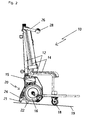
- the invention is in one embodiment in the FIGS. 1 to 3 and is explained in more detail in the following description of the figures. All features of the invention are shown in a highly schematic and are not to scale. The invention is not limited to the embodiments given above. Rather, a number of variants are conceivable, which make use of the features of the invention even with fundamentally different type of execution.
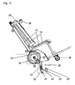
- the ascending leg 20 has, as a first support, at least under load, a non-rotatable support body 21 and as a second support a rotatable roller body 22, which is fastened by a screw 23 releasably attached to the two supports connecting web 24 (see Fig. 3 ).
- the ascending leg 20 has been pivoted by the electromechanical stair climbing device 15 such that neither the support body 21 nor the rolling body 22 touch the bottom surface 19. Therefore, the impeller 16 rests on the ground surface 19, and a known method of the stair climbing and transport device 10 via the wheels 16 and the steering wheels 18th may happen; but with a certain limitation in mobility.
- the stair climbing and transport device 10 is shown with resting on the bottom surface 19 rolling bodies 22.
- the ascending leg 20 has been moved in such a way by the stair climbing device 15, that the support body 21 remain spaced from the bottom surface 19 and the impeller 16 is raised to also no longer be in contact with the bottom surface 19.
- the stair climbing and transport device 10 on the rolling elements 22 and the steering wheels 18 in a confined space tax and moved.
- the invention relates to a stair climbing and transport device 10 for the transport of objects of any kind and / or people, with a frame structure 12, in addition to a load receiving device 14 for the object to be transported and / or for the person to be transported wheels 16, steering wheels 18 and Controls 28 are provided.
- a load receiving device 14 for the object to be transported and / or for the person to be transported wheels 16, steering wheels 18 and Controls 28 are provided.
- at least one rolling element 22 is provided, which is spaced in a first position when resting the wheels 16 on a bottom surface 19 of the bottom surface 19, and in a second position on the bottom surface 19, the load of the stair climbing and transport device 10 receiving, rests and at the same time the wheels 16 are spaced from the bottom surface 19.
- two spaced-apart supports are provided, wherein a first support ends in a rotationally fixed support body 21 and a second support the rotatable roller body 22 has.
Landscapes
- Engineering & Computer Science (AREA)
- Chemical & Material Sciences (AREA)
- Combustion & Propulsion (AREA)
- Transportation (AREA)
- Mechanical Engineering (AREA)
- Health & Medical Sciences (AREA)
- Life Sciences & Earth Sciences (AREA)
- Animal Behavior & Ethology (AREA)
- General Health & Medical Sciences (AREA)
- Public Health (AREA)
- Veterinary Medicine (AREA)
- Handcart (AREA)
Abstract
Description
- Die Erfindung betrifft eine Treppensteig- und Transportvorrichtung zum Transport von Gegenständen jedweder Art und/oder Personen, mit einer Rahmenkonstruktion, an der neben einer Lastaufnahmeeinrichtung für den zu transportierenden Gegenstand und/oder für die zu transportierende Person Laufräder, Lenkräder und Bedienelemente vorgesehen sind, wobei im Bereich der Laufräder mindestens ein Rollkörper vorgesehen ist, der in einer ersten Lage bei Auflage der Laufräder auf einer Bodenoberfläche von der Bodenoberfläche beabstandet ist, und in einer zweiten Lage auf der Bodenoberfläche, die Last der Treppensteig- und Transportvorrichtung aufnehmend, aufliegt und dabei gleichzeitig die Laufräder von der Bodenoberfläche beabstandet sind.
- Derartige Treppensteig- und Transportvorrichtungen können zum Transport von Gegenständen jedweder Art und/oder Personen insbesondere zum Transport über eine Treppe verwendet werden. Eine derartige Treppensteig- und Transportvorrichtung ist zum Beispiel aus der
DE 195 19 109 A1 bekannt geworden. Darin erfolgt ein Treppenauf- oder Abstieg durch das zyklische Abstützen von Trägern bzw. an deren Enden befestigte Stützelemente auf aufeinander folgende Trittstufen sowie damit verbundenes, synchrones Hochstemmen der Treppensteig- und Transportvorrichtung um die entsprechende Höhe der Setzstufe auf die nächstgelegene Treppenstufe durch einen elektromotorischen Antrieb. - Das in diesem Fall aus zwei Trägern und an deren Enden vorgesehenen Stützrädern bestehende Stütz- und Stemmelement kann in speziellen Ausführungsformen auch andersartig ausgebildetes sein. So zum Beispiel das Steigbein der von der Firma AAT Alber Antriebstechnik GmbH vertriebenen Treppensteig- und Transportvorrichtung mit dem Namen "s-max". Es führt eine von einer elektromechanischen Treppensteigvorrichtung gesteuerte Bewegung nach obig angedeutetem Prinzip durch, um den Treppenauf- und Treppenabstieg vorzunehmen.
- Durch die relative Größe der Laufräder solcher Treppensteig- und Transportvorrichtungen haben sich in der Vergangenheit Probleme bei der Manövrierfähigkeit auf engerem Raum ergeben. Es konnte beispielsweise keine parallele Verschiebung der Treppensteig- und Transportvorrichtung vorgenommen werden, ohne mehrmalig hin- und her zu rangieren. Deshalb wurde, wie aus der
DE 20 2007 006 453 U1 bekannt, im Bereich der Laufräder mindestens ein Rollkörper angebracht, der in einer ersten Lage bei Auflage der Laufräder auf einer Bodenoberfläche von der Bodenoberfläche beabstandet ist, und in einer zweiten Lage auf der Bodenoberfläche, die Last der Treppensteig- und Transportvorrichtung aufnehmend, aufliegt und dabei gleichzeitig die Laufräder von der Bodenoberfläche beabstandet sind. Dies ermöglicht es, die Treppensteig- und Transportvorrichtung in der zweiten Lage im Zusammenspiel mit den Lenkrädern auch bei engen Platzverhältnissen uneingeschränkt in der Ebene zu verfahren. Es kann beispielsweise eine Drehung der Treppensteig- und Transportvorrichtung um deren Hochachse an Ort und Stelle vorgenommen werden. In der ersten Lage ist die Treppensteig- und Transportvorrichtung wie bekannt zu benutzen. - Bisherige Ausführungen von Treppensteig- und Transportvorrichtungen verfügen einerseits über elektromotorisch angetriebene Treppensteigvorrichtungen, die sich unterschiedlicher Kinematiken bedienen, um die Steigbewegung durchzuführen und andererseits, im Falle dass dies gewünscht ist, über eine weitere elektromotorisch angetriebene Kinematik, die den Einsatz der Rollkörper zum Zwecke der verbesserten Manövrierfähigkeit steuert. Abgesehen davon, dass derartige Lösungen durch ihre beiden separaten Antriebsmechanismen möglicherweise sehr kostenintensiv sind, kann die relativ hohe Komplexität einer solchen Treppensteig- und Transportvorrichtung auch zu einem höheren Wartungsaufwand führen.
- Aufgabe der Erfindung ist es daher, eine bekannte Treppensteig- und Transportvorrichtung so weiterzuentwickeln, dass deren konstruktiver Aufbau unter Beibehaltung der bekannten Funktionalität vereinfacht wird.
- Die Aufgabe wird erfindungsgemäß dadurch gelöst, dass am freien Ende des Steigbeins zwei voneinander beabstandete Auflager vorgesehen sind, wobei das erste Auflager in einem drehfesten Stützkörper endet und das zweite Auflager einen drehbaren Rollkörper aufweist.
- Der wesentliche Vorteil ist dabei, dass dann nur noch ein einziger Antriebsmechanismus benötigt wird, der sowohl weiterhin die Treppensteigfunktion übernimmt, als auch das entsprechende Steigbein derart verfahren kann, dass die Rollkörper wie für die zweite Lage kennzeichnend, das Verfahren der Treppensteig- und Transportvorrichtung auf engem Raum ermöglichen. Weiterhin vereinfacht sich natürlich die Bauweise durch die Kompaktheit der erfindungsgemäßen Lösung.
- Endet das erste Auflager in zwei voneinander beabstandeten Stützkörpern, so kann das erste Auflager material- und gewichtssparender ausgeführt werden als wenn es aus einem einzigen breiten Stützkörper hergestellt würde. Die seitliche Kippstabilität wird dadurch weiterhin beibehalten bzw. kann bei gleichem Materialeinsatz wie im Falle eines einzigen breiten Auflagers durch das Aufspannen einer größeren Beabstandung der zwei Stützkörper relativ gesehen vergrößert werden.
- Weist das zweite Auflager zwei voneinander beabstandete Rollkörper auf, so bedeutet dies beim Aufliegen dieser beiden Rollkörper auf der Bodenoberfläche, also einer Nutzung der Rollkörper nach der zweiten Lage, eine erhöhte Kippstabilität verglichen mit einer Ausführungsform, bei der nur ein Rollkörper vorgesehen ist.
- Weist der zwischen erstem und zweitem Auflager ausgebildete Steg eine abgewinkelte Form auf oder weisen die zwischen ersten und zweiten Auflagern ausgebildeten Stege eine abgewinkelte Form auf, so erhöht dies die Kompaktheit des oder der Steigbeine und somit auch die Kompaktheit der Treppensteig- und Transportvorrichtung. Dies ist bezüglich des Bewegungsablaufs des Steigbeins beim Treppensteigen von Vorteil. Das oder die Steigbeine sind dann beispielsweise leichter und einfacher am elektromechanischen Antriebssystem der Treppensteigeinrichtung vorbeizuführen. Des Weiteren ist eine abgewinkelte Form verglichen mit einer geraden Form, die weiter oben am Steigbein ansetzt, material- und gewichtssparender und am Steigbein auftretende Momente können optimiert aufgenommen werden.
- Ist der Rollkörper oder sind die Rollkörper an deren entsprechenden zweiten Auflagern lösbar vorgesehen, so hat dies den Vorteil eines möglichen Austauschens der Rollkörper. Die Auswechslung eines abgenutzten oder defekten Rollkörpers ist dann ohne größeren Aufwand möglich und die allgemeine Wartbarkeit der Treppensteig- und Transportvorrichtung ist verbessert.
- Liegt der mindestens eine Rollkörper über eine drehbare Kugel, ein Rad, einen Wälzkörper oder dergleichen auf der Bodenoberfläche auf, so ist eine individuelle Anpassung des Rollkörpers an die lokalen Bodenverhältnisse möglich. Wird die Treppensteig- und Transportvorrichtung beispielsweise auf Teppichböden verwendet, sind Rollkörper mit einer etwas größeren Auflagefläche dem punktuellen Kontakt einer Kugel vorzuziehen. Ähnliche Anforderungen können zum Beispiel auch beim Einsatz auf einem Holzparkett gegeben sein.
- Ist der mindestens eine Rollkörper den Laufrädern nachlaufend am Steigbein vorgesehen, das heißt, er liegt bei normaler nach vorne gerichteter Fahrtrichtung hinter den Lauf- und Lenkrädern, so verleiht dies der Treppensteig- und Transportvorrichtung eine besonders hohe Kippstabilität. Dies ist darin begründet, dass sich die Rollkörper durch den Nachlauf an weiter außen liegenden Punkten abstützen als dies normalerweise durch die Laufräder gegeben ist. Deshalb erhöht sich die Stabilisierung der Treppensteig- und Transportvorrichtung zusätzlich.
- Die Erfindung ist in einem Ausführungsbeispiel in den
Figuren 1 bis 3 dargestellt und wird in der nachfolgenden Figurenbeschreibung näher erläutert. Alle Merkmale der Erfindung sind stark schematisiert dargestellt und sind nicht maßstäblich zu verstehen. Die Erfindung beschränkt sich nicht auf die vorstehend angegebenen Ausführungsbeispiele. Vielmehr ist eine Anzahl von Varianten denkbar, welche auch bei grundsätzlich anders gearteter Ausführung von den Merkmalen der Erfindung Gebrauch machen. - Die
Figuren 1 bis 3 stellen die erfindungsgemäße Treppensteig- und Transportvorrichtung jeweils in der Seitenansicht dar. DieFigur 1 und2 zeigt die Treppensteig- und Transportvorrichtung jeweils bei deren Einsatz auf einer Ebene, wobei in derFigur 1 die erste Lage mit auf der Bodenoberfläche aufliegendem Laufrad dargestellt ist. In derFigur 2 ist die zweite Lage gezeigt, die sich dadurch auszeichnet, dass das Laufrad von der Bodenoberfläche beabstandet ist und die Treppensteig- und Transportvorrichtung über die Rollkörper und die Lenkräder auf der Bodenoberfläche aufliegt. Schließlich zeigt dieFigur 3 eine Momentaufnahme während des Treppenauf- oder Treppenabstiegs. - In der
Figur 1 ist mit 10 eine Treppensteig- und Transportvorrichtung bezeichnet. Diese besteht aus einer Rahmenkonstruktion 12 sowie einer sich daran anschließenden elektromechanischen Treppensteigeinrichtung 15, welche seitlich daran angebrachte Laufräder 16 sowie ein in der Treppensteigeinrichtung 15 gelagertes und teilweise daraus hinausragendes Steigbein 20 aufweist. An der Rahmenkonstruktion 12 ist des Weiteren eine Lastaufnahmeeinrichtung 14 für den zu transportierenden Gegenstand und/oder für die zu transportierende Person vorgesehen sowie zwei Lenkräder 18, die unter anderem zur Richtungsänderung beim Verfahren in der Ebene dienen. Ebenso sind Bedienelemente 28 an der Rahmenkonstruktion 12 vorgesehen, die die Bedienung der elektromechanischen Treppensteigeinrichtung 15 durch den Benutzer ermöglichen oder eine Verstellung/Verlängerung/Verschwenkung der Rahmenkonstruktion 12 erlauben. Das Steigbein 20 weist als erstes Auflager, zumindest bei Belastung, einen drehfesten Stützkörper 21 und als zweites Auflager einen drehbaren Rollkörper 22 auf, der über eine Schraube 23 lösbar an dem die beiden Auflager verbindenden Steg 24 befestigt ist (sieheFig. 3 ). In derFigur 1 ist das Steigbein 20 durch die elektromechanische Treppensteigeinrichtung 15 derart verschwenkt worden, dass weder der Stützkörper 21 noch der Rollkörper 22 die Bodenoberfläche 19 berühren. Deshalb liegt das Laufrad 16 auf der Bodenoberfläche 19 auf, und ein bekanntes Verfahren der Treppensteig- und Transportvorrichtung 10 über die Laufräder 16 und die Lenkräder 18 kann erfolgen; allerdings mit einer gewissen Einschränkung in der Mobilität. - In der
Figur 2 ist die Treppensteig- und Transportvorrichtung 10 mit auf der Bodenoberfläche 19 aufliegenden Rollkörpern 22 gezeigt. Das Steigbein 20 ist dabei derart von der Treppensteigeinrichtung 15 verfahren worden, dass die Stützkörper 21 von der Bodenoberfläche 19 beabstandet bleiben und das Laufrad 16 angehoben wird, um ebenfalls nicht mehr mit der Bodenoberfläche 19 in Kontakt zu stehen. In diesem Zustand ist die Treppensteig- und Transportvorrichtung 10 über die Rollkörper 22 und die Lenkräder 18 auf engstem Raum steuer- und verfahrbar. Es sind beispielsweise Drehungen um die Hochachse an Ort und Stelle, enge Kurvenradien oder auch Parallelverschiebungen der Treppensteig- und Transportvorrichtung 10 möglich. - In der
Figur 3 ist die Treppensteig- und Transportvorrichtung 10 in einer Phase des Treppenaufstiegs oder Treppenabstiegs dargestellt. Hierfür wird die Treppensteig- und Transportvorrichtung 10 vom Benutzer über die Handgriffe 26 ergriffen und gegenüber der Horizontalen, in Richtung auf die Treppe 30 zu, abgekippt. In dieser leichten Schräglage beginnt der Treppenauf- oder Abstieg durch das zyklische Abstützen der Stützkörper 21 auf den aufeinander folgenden Trittstufen 32 sowie das synchrone Hochstemmen der Treppensteig- und Transportvorrichtung 10 um die entsprechende Höhe der Setzstufe 34. Der Steg 24 mit angebrachten Rollkörpern 22 berührt dabei weder Setzstufe 34 noch Trittstufe 32. - Die Erfindung betrifft eine Treppensteig- und Transportvorrichtung 10 zum Transport von Gegenständen jedweder Art und/oder Personen, mit einer Rahmenkonstruktion 12, an der neben einer Lastaufnahmeeinrichtung 14 für den zu transportierenden Gegenstand und/oder für die zu transportierende Person Laufräder 16, Lenkräder 18 und Bedienelemente 28 vorgesehen sind. Im Bereich der Laufräder 16 ist mindestens ein Rollkörper 22 vorgesehen, der in einer ersten Lage bei Auflage der Laufräder 16 auf einer Bodenoberfläche 19 von der Bodenoberfläche 19 beabstandet ist, und in einer zweiten Lage auf der Bodenoberfläche 19, die Last der Treppensteig- und Transportvorrichtung 10 aufnehmend, aufliegt und dabei gleichzeitig die Laufräder 16 von der Bodenoberfläche 19 beabstandet sind. Am freien Ende eines Steigbeins 20 sind zwei voneinander beabstandete Auflager vorgesehen, wobei ein erstes Auflager in einem drehfesten Stützkörper 21 endet und ein zweites Auflager den drehbaren Rollkörper 22 aufweist.
Claims (7)
- Treppensteig- und Transportvorrichtung (10) zum Transport von Gegenständen jedweder Art und/oder Personen, mit einer Rahmenkonstruktion (12), an der neben einer Lastaufnahmeeinrichtung (14) für den zu transportierenden Gegenstand und/oder für die zu transportierende Person Laufräder (16), Lenkräder (18) und Bedienelemente (28) vorgesehen sind, wobei im Bereich der Laufräder (16) mindestens ein Rollkörper (22) vorgesehen ist, der in einer ersten Lage bei Auflage der Laufräder (16) auf einer Bodenoberfläche (19) von der Bodenoberfläche (19) beabstandet ist, und in einer zweiten Lage auf der Bodenoberfläche (19), die Last der Treppensteig- und Transportvorrichtung (10) aufnehmend, aufliegt und dabei gleichzeitig die Laufräder (16) von der Bodenoberfläche (19) beabstandet sind,
dadurch gekennzeichnet, dass
am freien Ende eines Steigbeins (20) zwei voneinander beabstandete Auflager vorgesehen sind, wobei ein erstes Auflager in einem drehfesten Stützkörper (21) endet und ein zweites Auflager den drehbaren Rollkörper (22) aufweist. - Treppensteig- und Transportvorrichtung (10) nach Anspruch 1,
dadurch gekennzeichnet, dass
das erste Auflager in zwei voneinander beabstandeten Stützkörpern (21) endet. - Treppensteig- und Transportvorrichtung (10) nach einem der vorhergehenden Ansprüche, dadurch gekennzeichnet, dass
das zweite Auflager zwei voneinander beabstandete Rollkörper (22) aufweist. - Treppensteig- und Transportvorrichtung (10) nach einem der vorhergehenden Ansprüche, dadurch gekennzeichnet, dass
ein zwischen erstem und zweiten Auflager ausgebildeter Steg (24) oder zwischen ersten und zweiten Auflagern ausgebildete Stege (24) eine abgewinkelte Form aufweisen. - Treppensteig- und Transportvorrichtung (10) nach Anspruch 1,
dadurch gekennzeichnet, dass
der mindestens eine Rollkörper (22) an dem zweiten Auflager lösbar vorgesehen ist. - Treppensteig- und Transportvorrichtung (10) nach einem der vorhergehenden Ansprüche,
dadurch gekennzeichnet, dass
der mindestens eine Rollkörper (22) über eine drehbare Kugel, ein Rad, einen Wälzkörper oder dergleichen auf der Bodenoberfläche (19) aufliegt. - Treppensteig- und Transportvorrichtung (10) nach einem der vorhergehenden Ansprüche,
dadurch gekennzeichnet, dass
der mindestens eine Rollkörper (22) den Laufrädern (16) nachlaufend am Steigbein (22) vorgesehen ist.
Applications Claiming Priority (1)
| Application Number | Priority Date | Filing Date | Title |
|---|---|---|---|
| DE200820005311 DE202008005311U1 (de) | 2008-04-17 | 2008-04-17 | Treppensteig- und Transportvorrichtung |
Publications (3)
| Publication Number | Publication Date |
|---|---|
| EP2110294A2 true EP2110294A2 (de) | 2009-10-21 |
| EP2110294A3 EP2110294A3 (de) | 2010-03-24 |
| EP2110294B1 EP2110294B1 (de) | 2014-03-26 |
Family
ID=39587811
Family Applications (1)
| Application Number | Title | Priority Date | Filing Date |
|---|---|---|---|
| EP20090001276 Not-in-force EP2110294B1 (de) | 2008-04-17 | 2009-01-30 | Treppensteig- und Transportvorrichtung |
Country Status (2)
| Country | Link |
|---|---|
| EP (1) | EP2110294B1 (de) |
| DE (1) | DE202008005311U1 (de) |
Cited By (4)
| Publication number | Priority date | Publication date | Assignee | Title |
|---|---|---|---|---|
| GB2478340A (en) * | 2010-03-05 | 2011-09-07 | Joona Ltd | Hand-propelled vehicle with resiliently mounted further wheel for cushioning |
| RU2510347C2 (ru) * | 2012-07-06 | 2014-03-27 | Федеральное государственное бюджетное образовательное учреждение высшего профессионального образования "Санкт-Петербургский государственный политехнический университет" (ФГБОУ ВПО "СПбГПУ") | Автоматический тормоз транспортного средства преимущественно для перемещения человека по лестницам и на эскалаторах |
| US8764027B1 (en) | 2013-01-28 | 2014-07-01 | Michael Della Polla | Slab dolly |
| CN104434431A (zh) * | 2014-12-09 | 2015-03-25 | 国家康复辅具研究中心 | 一种便携式爬楼装置 |
Families Citing this family (2)
| Publication number | Priority date | Publication date | Assignee | Title |
|---|---|---|---|---|
| DE102015202950A1 (de) | 2015-02-18 | 2016-01-21 | Schaeffler Technologies AG & Co. KG | Treppenroboter zum Ersteigen einer Treppe sowie Verfahren |
| RU2629465C1 (ru) * | 2016-10-28 | 2017-08-29 | Николай Петрович Дядченко | Подвеска колеса средства передвижения |
Citations (2)
| Publication number | Priority date | Publication date | Assignee | Title |
|---|---|---|---|---|
| DE19519109A1 (de) | 1995-05-24 | 1996-11-28 | Alber Antriebstechnik Gmbh | Transportvorrichtung |
| DE202007006453U1 (de) | 2007-05-05 | 2007-08-02 | Aat Alber Antriebstechnik Gmbh | Treppensteig- und Transportvorrichtung |
Family Cites Families (4)
| Publication number | Priority date | Publication date | Assignee | Title |
|---|---|---|---|---|
| US4109740A (en) * | 1975-05-22 | 1978-08-29 | Step-Rite Limited | Stair climbing device |
| DE19614319A1 (de) * | 1996-04-11 | 1997-10-16 | Alber Antriebstechnik Gmbh | Transportvorrichtung |
| US6341784B1 (en) * | 1998-11-17 | 2002-01-29 | Otto Bock Orthopaedische Industrie Besitz-Und Verwaltungs-Kommanditgesellschaft | Motor-driven stair climbing device |
| DE20116026U1 (de) * | 2001-09-29 | 2002-02-14 | Kotlarov, Peter, 27283 Verden | Treppensteigende Vorrichtung |
-
2008
- 2008-04-17 DE DE200820005311 patent/DE202008005311U1/de not_active Expired - Lifetime
-
2009
- 2009-01-30 EP EP20090001276 patent/EP2110294B1/de not_active Not-in-force
Patent Citations (2)
| Publication number | Priority date | Publication date | Assignee | Title |
|---|---|---|---|---|
| DE19519109A1 (de) | 1995-05-24 | 1996-11-28 | Alber Antriebstechnik Gmbh | Transportvorrichtung |
| DE202007006453U1 (de) | 2007-05-05 | 2007-08-02 | Aat Alber Antriebstechnik Gmbh | Treppensteig- und Transportvorrichtung |
Cited By (6)
| Publication number | Priority date | Publication date | Assignee | Title |
|---|---|---|---|---|
| GB2478340A (en) * | 2010-03-05 | 2011-09-07 | Joona Ltd | Hand-propelled vehicle with resiliently mounted further wheel for cushioning |
| GB2478340B (en) * | 2010-03-05 | 2012-11-14 | Joona Ltd | Hand-propelled vehicle |
| RU2510347C2 (ru) * | 2012-07-06 | 2014-03-27 | Федеральное государственное бюджетное образовательное учреждение высшего профессионального образования "Санкт-Петербургский государственный политехнический университет" (ФГБОУ ВПО "СПбГПУ") | Автоматический тормоз транспортного средства преимущественно для перемещения человека по лестницам и на эскалаторах |
| US8764027B1 (en) | 2013-01-28 | 2014-07-01 | Michael Della Polla | Slab dolly |
| CN104434431A (zh) * | 2014-12-09 | 2015-03-25 | 国家康复辅具研究中心 | 一种便携式爬楼装置 |
| CN104434431B (zh) * | 2014-12-09 | 2016-11-02 | 国家康复辅具研究中心 | 一种便携式爬楼装置 |
Also Published As
| Publication number | Publication date |
|---|---|
| EP2110294A3 (de) | 2010-03-24 |
| DE202008005311U1 (de) | 2008-07-03 |
| EP2110294B1 (de) | 2014-03-26 |
Similar Documents
| Publication | Publication Date | Title |
|---|---|---|
| DE3615572C2 (de) | Krankenhausbett | |
| DE3333570C2 (de) | ||
| EP2110294B1 (de) | Treppensteig- und Transportvorrichtung | |
| DE3121166A1 (de) | Gehgestell fuer gehbehinderte | |
| DE60131178T2 (de) | Gehwagen | |
| DE3225354A1 (de) | Rollstuhl fuer behinderte | |
| DE102020001401B4 (de) | Beförderungsmittel für die Fortbewegung oder den Transport von Personen oder Waren, insbesondere als Rollstuhl | |
| DE29721477U1 (de) | Motorisch betriebene Treppensteigvorrichtung | |
| DE102012105031A1 (de) | Treppensteigvorrichtung mit einem zweiarmigen Steigelement | |
| DE7639756U1 (de) | Geraet zum transport von personen und guetern, auch ueber treppen und steigungen | |
| DE102016220869A1 (de) | Treppensteighilfe | |
| DE1924117U (de) | Rollbares arbeitsgeruest. | |
| DE4310003C1 (de) | Bett, insbesondere Kranken- und/oder Pflegebett | |
| AT509655B1 (de) | Treppensteigmechanismus | |
| DE19639836A1 (de) | Vorrichtung zum Befahren einer Treppe | |
| DE102020001400B4 (de) | Beförderungsmittel für die Fortbewegung oder den Transport von Personen oder Waren, insbesondere als Rollstuhl | |
| DE69800024T2 (de) | Treppenlift | |
| DE102009014326B4 (de) | Transportvorrichtung | |
| DE19732950A1 (de) | Rollstuhlschaukel | |
| EP0056490A2 (de) | Handkarre | |
| DE102011010909A1 (de) | Bewegliche Beinablagen zum Auf- und Abständern oder zur Sitzabsenkung eines kurvenneigbaren Zwei- oder Dreirades | |
| EP2893842A2 (de) | Sitz-/Liegemöbel | |
| EP1990036A2 (de) | Treppensteig- und Transportvorrichtung | |
| DE9316974U1 (de) | Von Hand bewegbares Transportgerät | |
| DE4424118C1 (de) | Bett, insbesondere Kranken- und/oder Pflegebett |
Legal Events
| Date | Code | Title | Description |
|---|---|---|---|
| PUAI | Public reference made under article 153(3) epc to a published international application that has entered the european phase |
Free format text: ORIGINAL CODE: 0009012 |
|
| AK | Designated contracting states |
Kind code of ref document: A2 Designated state(s): AT BE BG CH CY CZ DE DK EE ES FI FR GB GR HR HU IE IS IT LI LT LU LV MC MK MT NL NO PL PT RO SE SI SK TR |
|
| AX | Request for extension of the european patent |
Extension state: AL BA RS |
|
| PUAL | Search report despatched |
Free format text: ORIGINAL CODE: 0009013 |
|
| AK | Designated contracting states |
Kind code of ref document: A3 Designated state(s): AT BE BG CH CY CZ DE DK EE ES FI FR GB GR HR HU IE IS IT LI LT LU LV MC MK MT NL NO PL PT RO SE SI SK TR |
|
| AX | Request for extension of the european patent |
Extension state: AL BA RS |
|
| 17P | Request for examination filed |
Effective date: 20100907 |
|
| 17Q | First examination report despatched |
Effective date: 20101012 |
|
| AKX | Designation fees paid |
Designated state(s): AT BE BG CH CY CZ DE DK EE ES FI FR GB GR HR HU IE IS IT LI LT LU LV MC MK MT NL NO PL PT RO SE SI SK TR |
|
| REG | Reference to a national code |
Ref country code: DE Ref legal event code: R079 Ref document number: 502009009046 Country of ref document: DE Free format text: PREVIOUS MAIN CLASS: B62B0005020000 Ipc: A61G0005040000 |
|
| GRAP | Despatch of communication of intention to grant a patent |
Free format text: ORIGINAL CODE: EPIDOSNIGR1 |
|
| RIC1 | Information provided on ipc code assigned before grant |
Ipc: A61G 5/06 20060101ALI20130806BHEP Ipc: B62B 5/02 20060101ALI20130806BHEP Ipc: A61G 5/04 20130101AFI20130806BHEP |
|
| INTG | Intention to grant announced |
Effective date: 20130906 |
|
| GRAS | Grant fee paid |
Free format text: ORIGINAL CODE: EPIDOSNIGR3 |
|
| GRAP | Despatch of communication of intention to grant a patent |
Free format text: ORIGINAL CODE: EPIDOSNIGR1 |
|
| INTG | Intention to grant announced |
Effective date: 20140116 |
|
| GRAA | (expected) grant |
Free format text: ORIGINAL CODE: 0009210 |
|
| AK | Designated contracting states |
Kind code of ref document: B1 Designated state(s): AT BE BG CH CY CZ DE DK EE ES FI FR GB GR HR HU IE IS IT LI LT LU LV MC MK MT NL NO PL PT RO SE SI SK TR |
|
| REG | Reference to a national code |
Ref country code: GB Ref legal event code: FG4D Free format text: NOT ENGLISH |
|
| REG | Reference to a national code |
Ref country code: CH Ref legal event code: EP |
|
| REG | Reference to a national code |
Ref country code: AT Ref legal event code: REF Ref document number: 658544 Country of ref document: AT Kind code of ref document: T Effective date: 20140415 |
|
| REG | Reference to a national code |
Ref country code: IE Ref legal event code: FG4D Free format text: LANGUAGE OF EP DOCUMENT: GERMAN |
|
| REG | Reference to a national code |
Ref country code: DE Ref legal event code: R096 Ref document number: 502009009046 Country of ref document: DE Effective date: 20140508 |
|
| PG25 | Lapsed in a contracting state [announced via postgrant information from national office to epo] |
Ref country code: LT Free format text: LAPSE BECAUSE OF FAILURE TO SUBMIT A TRANSLATION OF THE DESCRIPTION OR TO PAY THE FEE WITHIN THE PRESCRIBED TIME-LIMIT Effective date: 20140326 Ref country code: NO Free format text: LAPSE BECAUSE OF FAILURE TO SUBMIT A TRANSLATION OF THE DESCRIPTION OR TO PAY THE FEE WITHIN THE PRESCRIBED TIME-LIMIT Effective date: 20140626 |
|
| REG | Reference to a national code |
Ref country code: NL Ref legal event code: VDEP Effective date: 20140326 |
|
| REG | Reference to a national code |
Ref country code: LT Ref legal event code: MG4D |
|
| PG25 | Lapsed in a contracting state [announced via postgrant information from national office to epo] |
Ref country code: SE Free format text: LAPSE BECAUSE OF FAILURE TO SUBMIT A TRANSLATION OF THE DESCRIPTION OR TO PAY THE FEE WITHIN THE PRESCRIBED TIME-LIMIT Effective date: 20140326 Ref country code: FI Free format text: LAPSE BECAUSE OF FAILURE TO SUBMIT A TRANSLATION OF THE DESCRIPTION OR TO PAY THE FEE WITHIN THE PRESCRIBED TIME-LIMIT Effective date: 20140326 |
|
| PG25 | Lapsed in a contracting state [announced via postgrant information from national office to epo] |
Ref country code: HR Free format text: LAPSE BECAUSE OF FAILURE TO SUBMIT A TRANSLATION OF THE DESCRIPTION OR TO PAY THE FEE WITHIN THE PRESCRIBED TIME-LIMIT Effective date: 20140326 Ref country code: LV Free format text: LAPSE BECAUSE OF FAILURE TO SUBMIT A TRANSLATION OF THE DESCRIPTION OR TO PAY THE FEE WITHIN THE PRESCRIBED TIME-LIMIT Effective date: 20140326 |
|
| PG25 | Lapsed in a contracting state [announced via postgrant information from national office to epo] |
Ref country code: CY Free format text: LAPSE BECAUSE OF FAILURE TO SUBMIT A TRANSLATION OF THE DESCRIPTION OR TO PAY THE FEE WITHIN THE PRESCRIBED TIME-LIMIT Effective date: 20140326 Ref country code: RO Free format text: LAPSE BECAUSE OF FAILURE TO SUBMIT A TRANSLATION OF THE DESCRIPTION OR TO PAY THE FEE WITHIN THE PRESCRIBED TIME-LIMIT Effective date: 20140326 Ref country code: CZ Free format text: LAPSE BECAUSE OF FAILURE TO SUBMIT A TRANSLATION OF THE DESCRIPTION OR TO PAY THE FEE WITHIN THE PRESCRIBED TIME-LIMIT Effective date: 20140326 Ref country code: BG Free format text: LAPSE BECAUSE OF FAILURE TO SUBMIT A TRANSLATION OF THE DESCRIPTION OR TO PAY THE FEE WITHIN THE PRESCRIBED TIME-LIMIT Effective date: 20140626 Ref country code: IS Free format text: LAPSE BECAUSE OF FAILURE TO SUBMIT A TRANSLATION OF THE DESCRIPTION OR TO PAY THE FEE WITHIN THE PRESCRIBED TIME-LIMIT Effective date: 20140726 Ref country code: NL Free format text: LAPSE BECAUSE OF FAILURE TO SUBMIT A TRANSLATION OF THE DESCRIPTION OR TO PAY THE FEE WITHIN THE PRESCRIBED TIME-LIMIT Effective date: 20140326 Ref country code: EE Free format text: LAPSE BECAUSE OF FAILURE TO SUBMIT A TRANSLATION OF THE DESCRIPTION OR TO PAY THE FEE WITHIN THE PRESCRIBED TIME-LIMIT Effective date: 20140326 |
|
| PG25 | Lapsed in a contracting state [announced via postgrant information from national office to epo] |
Ref country code: PL Free format text: LAPSE BECAUSE OF FAILURE TO SUBMIT A TRANSLATION OF THE DESCRIPTION OR TO PAY THE FEE WITHIN THE PRESCRIBED TIME-LIMIT Effective date: 20140326 Ref country code: SK Free format text: LAPSE BECAUSE OF FAILURE TO SUBMIT A TRANSLATION OF THE DESCRIPTION OR TO PAY THE FEE WITHIN THE PRESCRIBED TIME-LIMIT Effective date: 20140326 Ref country code: ES Free format text: LAPSE BECAUSE OF FAILURE TO SUBMIT A TRANSLATION OF THE DESCRIPTION OR TO PAY THE FEE WITHIN THE PRESCRIBED TIME-LIMIT Effective date: 20140326 |
|
| PG25 | Lapsed in a contracting state [announced via postgrant information from national office to epo] |
Ref country code: PT Free format text: LAPSE BECAUSE OF FAILURE TO SUBMIT A TRANSLATION OF THE DESCRIPTION OR TO PAY THE FEE WITHIN THE PRESCRIBED TIME-LIMIT Effective date: 20140728 |
|
| REG | Reference to a national code |
Ref country code: DE Ref legal event code: R097 Ref document number: 502009009046 Country of ref document: DE |
|
| PG25 | Lapsed in a contracting state [announced via postgrant information from national office to epo] |
Ref country code: DK Free format text: LAPSE BECAUSE OF FAILURE TO SUBMIT A TRANSLATION OF THE DESCRIPTION OR TO PAY THE FEE WITHIN THE PRESCRIBED TIME-LIMIT Effective date: 20140326 |
|
| PLBE | No opposition filed within time limit |
Free format text: ORIGINAL CODE: 0009261 |
|
| STAA | Information on the status of an ep patent application or granted ep patent |
Free format text: STATUS: NO OPPOSITION FILED WITHIN TIME LIMIT |
|
| 26N | No opposition filed |
Effective date: 20150106 |
|
| REG | Reference to a national code |
Ref country code: DE Ref legal event code: R097 Ref document number: 502009009046 Country of ref document: DE Effective date: 20150106 |
|
| PG25 | Lapsed in a contracting state [announced via postgrant information from national office to epo] |
Ref country code: BE Free format text: LAPSE BECAUSE OF NON-PAYMENT OF DUE FEES Effective date: 20150131 |
|
| PG25 | Lapsed in a contracting state [announced via postgrant information from national office to epo] |
Ref country code: SI Free format text: LAPSE BECAUSE OF FAILURE TO SUBMIT A TRANSLATION OF THE DESCRIPTION OR TO PAY THE FEE WITHIN THE PRESCRIBED TIME-LIMIT Effective date: 20140326 |
|
| REG | Reference to a national code |
Ref country code: CH Ref legal event code: PL |
|
| PG25 | Lapsed in a contracting state [announced via postgrant information from national office to epo] |
Ref country code: LU Free format text: LAPSE BECAUSE OF FAILURE TO SUBMIT A TRANSLATION OF THE DESCRIPTION OR TO PAY THE FEE WITHIN THE PRESCRIBED TIME-LIMIT Effective date: 20150130 |
|
| PG25 | Lapsed in a contracting state [announced via postgrant information from national office to epo] |
Ref country code: MC Free format text: LAPSE BECAUSE OF FAILURE TO SUBMIT A TRANSLATION OF THE DESCRIPTION OR TO PAY THE FEE WITHIN THE PRESCRIBED TIME-LIMIT Effective date: 20140326 |
|
| PG25 | Lapsed in a contracting state [announced via postgrant information from national office to epo] |
Ref country code: LI Free format text: LAPSE BECAUSE OF NON-PAYMENT OF DUE FEES Effective date: 20150131 Ref country code: CH Free format text: LAPSE BECAUSE OF NON-PAYMENT OF DUE FEES Effective date: 20150131 |
|
| REG | Reference to a national code |
Ref country code: FR Ref legal event code: ST Effective date: 20150930 |
|
| REG | Reference to a national code |
Ref country code: IE Ref legal event code: MM4A |
|
| PG25 | Lapsed in a contracting state [announced via postgrant information from national office to epo] |
Ref country code: FR Free format text: LAPSE BECAUSE OF NON-PAYMENT OF DUE FEES Effective date: 20150202 |
|
| PG25 | Lapsed in a contracting state [announced via postgrant information from national office to epo] |
Ref country code: IE Free format text: LAPSE BECAUSE OF NON-PAYMENT OF DUE FEES Effective date: 20150130 |
|
| REG | Reference to a national code |
Ref country code: AT Ref legal event code: MM01 Ref document number: 658544 Country of ref document: AT Kind code of ref document: T Effective date: 20150130 |
|
| PG25 | Lapsed in a contracting state [announced via postgrant information from national office to epo] |
Ref country code: AT Free format text: LAPSE BECAUSE OF NON-PAYMENT OF DUE FEES Effective date: 20150130 |
|
| PG25 | Lapsed in a contracting state [announced via postgrant information from national office to epo] |
Ref country code: GR Free format text: LAPSE BECAUSE OF FAILURE TO SUBMIT A TRANSLATION OF THE DESCRIPTION OR TO PAY THE FEE WITHIN THE PRESCRIBED TIME-LIMIT Effective date: 20140627 |
|
| PG25 | Lapsed in a contracting state [announced via postgrant information from national office to epo] |
Ref country code: MT Free format text: LAPSE BECAUSE OF FAILURE TO SUBMIT A TRANSLATION OF THE DESCRIPTION OR TO PAY THE FEE WITHIN THE PRESCRIBED TIME-LIMIT Effective date: 20140326 |
|
| PG25 | Lapsed in a contracting state [announced via postgrant information from national office to epo] |
Ref country code: HU Free format text: LAPSE BECAUSE OF FAILURE TO SUBMIT A TRANSLATION OF THE DESCRIPTION OR TO PAY THE FEE WITHIN THE PRESCRIBED TIME-LIMIT; INVALID AB INITIO Effective date: 20090130 |
|
| PG25 | Lapsed in a contracting state [announced via postgrant information from national office to epo] |
Ref country code: TR Free format text: LAPSE BECAUSE OF FAILURE TO SUBMIT A TRANSLATION OF THE DESCRIPTION OR TO PAY THE FEE WITHIN THE PRESCRIBED TIME-LIMIT Effective date: 20140326 |
|
| PG25 | Lapsed in a contracting state [announced via postgrant information from national office to epo] |
Ref country code: MK Free format text: LAPSE BECAUSE OF FAILURE TO SUBMIT A TRANSLATION OF THE DESCRIPTION OR TO PAY THE FEE WITHIN THE PRESCRIBED TIME-LIMIT Effective date: 20140326 |
|
| PGFP | Annual fee paid to national office [announced via postgrant information from national office to epo] |
Ref country code: DE Payment date: 20240123 Year of fee payment: 16 Ref country code: GB Payment date: 20240124 Year of fee payment: 16 |
|
| PGFP | Annual fee paid to national office [announced via postgrant information from national office to epo] |
Ref country code: IT Payment date: 20240131 Year of fee payment: 16 |
|
| REG | Reference to a national code |
Ref country code: DE Ref legal event code: R119 Ref document number: 502009009046 Country of ref document: DE |
|
| GBPC | Gb: european patent ceased through non-payment of renewal fee |
Effective date: 20250130 |
|
| PG25 | Lapsed in a contracting state [announced via postgrant information from national office to epo] |
Ref country code: DE Free format text: LAPSE BECAUSE OF NON-PAYMENT OF DUE FEES Effective date: 20250801 |
|
| PG25 | Lapsed in a contracting state [announced via postgrant information from national office to epo] |
Ref country code: GB Free format text: LAPSE BECAUSE OF NON-PAYMENT OF DUE FEES Effective date: 20250130 |
|
| PG25 | Lapsed in a contracting state [announced via postgrant information from national office to epo] |
Ref country code: IT Free format text: LAPSE BECAUSE OF NON-PAYMENT OF DUE FEES Effective date: 20250130 |