EP2110314A2 - Triebwerkseinlassenteisungsvorrichtung und Verfahren zur Verhinderung von Eisbildung - Google Patents
Triebwerkseinlassenteisungsvorrichtung und Verfahren zur Verhinderung von Eisbildung Download PDFInfo
- Publication number
- EP2110314A2 EP2110314A2 EP09250284A EP09250284A EP2110314A2 EP 2110314 A2 EP2110314 A2 EP 2110314A2 EP 09250284 A EP09250284 A EP 09250284A EP 09250284 A EP09250284 A EP 09250284A EP 2110314 A2 EP2110314 A2 EP 2110314A2
- Authority
- EP
- European Patent Office
- Prior art keywords
- fairings
- engine inlet
- group
- electric current
- ice protection
- Prior art date
- Legal status (The legal status is an assumption and is not a legal conclusion. Google has not performed a legal analysis and makes no representation as to the accuracy of the status listed.)
- Withdrawn
Links
Images

Classifications
-
- F—MECHANICAL ENGINEERING; LIGHTING; HEATING; WEAPONS; BLASTING
- F02—COMBUSTION ENGINES; HOT-GAS OR COMBUSTION-PRODUCT ENGINE PLANTS
- F02C—GAS-TURBINE PLANTS; AIR INTAKES FOR JET-PROPULSION PLANTS; CONTROLLING FUEL SUPPLY IN AIR-BREATHING JET-PROPULSION PLANTS
- F02C7/00—Features, components parts, details or accessories, not provided for in, or of interest apart form groups F02C1/00 - F02C6/00; Air intakes for jet-propulsion plants
- F02C7/04—Air intakes for gas-turbine plants or jet-propulsion plants
- F02C7/047—Heating to prevent icing
-
- F—MECHANICAL ENGINEERING; LIGHTING; HEATING; WEAPONS; BLASTING
- F01—MACHINES OR ENGINES IN GENERAL; ENGINE PLANTS IN GENERAL; STEAM ENGINES
- F01D—NON-POSITIVE DISPLACEMENT MACHINES OR ENGINES, e.g. STEAM TURBINES
- F01D25/00—Component parts, details, or accessories, not provided for in, or of interest apart from, other groups
- F01D25/02—De-icing means for engines having icing phenomena
-
- B—PERFORMING OPERATIONS; TRANSPORTING
- B64—AIRCRAFT; AVIATION; COSMONAUTICS
- B64D—EQUIPMENT FOR FITTING IN OR TO AIRCRAFT; FLIGHT SUITS; PARACHUTES; ARRANGEMENT OR MOUNTING OF POWER PLANTS OR PROPULSION TRANSMISSIONS IN AIRCRAFT
- B64D33/00—Arrangement in aircraft of power plant parts or auxiliaries not otherwise provided for
- B64D33/02—Arrangement in aircraft of power plant parts or auxiliaries not otherwise provided for of combustion air intakes
- B64D2033/0233—Arrangement in aircraft of power plant parts or auxiliaries not otherwise provided for of combustion air intakes comprising de-icing means
-
- Y—GENERAL TAGGING OF NEW TECHNOLOGICAL DEVELOPMENTS; GENERAL TAGGING OF CROSS-SECTIONAL TECHNOLOGIES SPANNING OVER SEVERAL SECTIONS OF THE IPC; TECHNICAL SUBJECTS COVERED BY FORMER USPC CROSS-REFERENCE ART COLLECTIONS [XRACs] AND DIGESTS
- Y02—TECHNOLOGIES OR APPLICATIONS FOR MITIGATION OR ADAPTATION AGAINST CLIMATE CHANGE
- Y02T—CLIMATE CHANGE MITIGATION TECHNOLOGIES RELATED TO TRANSPORTATION
- Y02T50/00—Aeronautics or air transport
- Y02T50/60—Efficient propulsion technologies, e.g. for aircraft
Definitions
- Engine inlet anti-icing systems commonly employ a thermal source, such as hot air bled from the engine core, which is applied to the engine inlet to melt or evaporate ice build-up on the external surfaces thereof.
- Electrothermal devices have also been used to prevent ice formation and remove ice from aircraft.
- Commonly employed electrothermal deicers use heating elements that are mounted on a flexible backing. These heating elements can then be attached to aircraft structures with an adhesive. Coatings containing heating elements have also been used.
- An exemplary embodiment of the invention is an engine inlet ice protection system having a plurality of fairings distributed generally evenly within an engine inlet.
- the fairings are grouped and distributed within the engine inlet so that fairings in one group are separated from each other by at least one fairing from a different group.
- the fairings have embedded electrical components that provide ice protection.
- Another exemplary embodiment of the invention is an engine inlet ice protection system having a plurality of grouped fairings with embedded electrical components to provide ice protection and a power distribution system.
- the power distribution system cycles electric current so that the fairing electrical components powered at a given time are generally evenly distributed within the engine inlet.
- An additional exemplary embodiment of the invention is an engine inlet ice protection system having first and second heating zones and a power distribution system.
- the first and second heating zones each have a plurality of fairings with embedded electrical components to provide ice protection.
- the power distribution system cycles current to the heating zones one zone at a time.
- a further exemplary embodiment of the invention includes a method of preventing and reducing ice formation and conditioning airflow in an engine inlet by activating a power distribution system to deliver electric current to fairings having embedded heating elements. Power is cycled to the fairings so that at a given time the fairings being powered are generally evenly distributed within the engine inlet.
- Another exemplary embodiment of the invention is an engine inlet ice protection system having seventeen grouped fairings with embedded electrical components and a power distribution system for cycling power to the grouped fairings one group at a time.
- the first, fifth, ninth, and fourteenth fairings form a first group.
- the second, fourth, eighth, eleventh, and fifteenth fairings form a second group.
- the third, seventh, twelfth, and sixteenth fairings form a third group.
- the sixth, tenth, thirteenth, and seventeenth fairings form a fourth group.
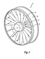
- FIG. 1 is a perspective view of an engine inlet.
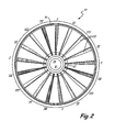
- FIG. 2 is a front view of an engine inlet with grouped fairings according to an exemplary embodiment of the invention.
- FIG. 3 is a front view of an engine inlet with grouped fairings according to an alternative embodiment of the invention.
- Exemplary embodiments of the invention include engine inlets having composite fairings and nosecones with embedded heating elements.
- the heating elements distributed generally evenly throughout the engine inlet, prevent or reduce ice formation by heating the structures (fairing or nosecone) in which they are located. Ice formation is prevented or reduced by the heating and any ice already formed on the structures is shed off by the combination of the heating (to melt the ice) and the airflow passing around the structure.
- the heating elements active at any one time are distributed throughout the engine inlet to prevent and reduce airflow disturbances.
- FIG. 1 illustrates one example of an engine inlet 10.
- Engine inlet 10 includes inner ring 12, nosecone 14, outer ring 16, a plurality of inner struts (not shown) extending from inner ring 12 to outer ring 16 and a plurality of fairings 20 surrounding the inner struts.
- Nosecone 14 is located at an upstream side of the engine inlet.
- the fairings 20 are located downstream from nosecone 14, and they surround and are bonded to the inner struts.
- the fairings 20 extend radially from inner ring 12 to outer ring 16.
- Variable vanes 18 are located downstream of the fairings 20 and inner struts. While FIG.
- FIG. 1 depicts seventeen fairings 20 (and therefore seventeen inner struts) within engine inlet 10, the number of inner struts and fairings present in the engine inlet is not limited by this illustration. Configurations with fewer or greater numbers of fairings and inner struts within the engine inlet are possible. The number of fairings and inner struts in a given engine inlet will depend on the size of the engine inlet and other factors.
- the fairings 20 contain heating elements (not shown) and other components that require electrical power.
- the heating elements may be of conventional type, for instance each can be formed as from a spray metal resistive layer disposed on fiberglass webs.
- the nosecone 14 may also contain heating elements and other components requiring electrical power. When active, the heating elements within the fairings 20 and nosecone 14 provide heat to reduce or prevent ice formation, thereby providing an optimal or designed flow of air into the engine inlet and to engine components farther downstream.
- the heating elements and other electrical components require an electric current (power) to operate. Electric current may be provided to the fairings and nosecone by a power source external to these structures (fairings and nosecone).
- Providing all the fairings 20 and nosecones 14 of multiple engine inlets 10 with electric current at one time may be burdensome on the aircraft power plant. By distributing the electric current to groups of structures on a cycled basis, the aircraft's power can be conserved and used more efficiently.
- Power distribution systems and the accompanying mechanisms for delivering electric current to different groups of structures within an engine inlet are generally known in the art.
- One example of a power distribution system suitable for use in an exemplary embodiment of the invention includes a combination of switches and pulse width modulation.
- An exemplary embodiment of the invention provides for a novel arrangement of fairing groups and, optionally, nosecone groups to which power is cycled within the engine inlet.
- Some engine inlets having fairings and nosecones with embedded heating elements may have power cycled to groups of the fairings and nosecones within the engine inlet one group at a time in a non-optimal fashion.
- These engine inlets (not claimed) generally have power distributed to heating elements in one part of the engine inlet at a time.
- the engine inlet may be grouped roughly into quarters, and fairings in one quarter of the engine inlet receive power at any one time (i.e. the first quarter receives power, then the second quarter, then the third quarter, and so on). This leaves large and unbroken expanses within the engine inlet without ice protection at any given time (the roughly three-quarters that do not receive power).
- a large drawback associated with this power cycling scheme is that the airflow passing over non-active ice protection elements may become disturbed due to ice formation and may not be conditioned for optimal engine performance. This provides opportunities for potential airflow disturbances in a large area within the engine inlet at any given time. Disturbed airflow passing through a large area within the engine inlet may cause significant problems downstream in the engine.
- the fairing ice protection system elements may not receive power.
- serious airflow problems can occur because one quarter of the engine inlet may develop ice and have disturbed airflow while that group's fairing elements may not become active again for three or four cycles (i.e. the other fairing groups receive power before the affected group).
- airflow passing through the affected group of the engine inlet may be disturbed for multiple cycles. This problem is compounded when airflow of multiple and/or adjacent groups are forced to wait their turn for power to activate their ice protection heating elements to remove ice and improve nearby airflow.
- FIG. 2 illustrates an engine inlet 10 with a plurality of generally evenly spaced fairings 20 extending from inner ring 12 to outer ring 16. Nosecone 14 is also present.
- Engine inlet 10 contains seventeen individual fairings 20. These seventeen fairings 20 are split into four groups, indicated by the various shading and hatching of FIG. 2 .
- the fairing groups are indicated in FIG. 2 by roman numerals. Fairings belonging to the same group are spaced throughout the engine inlet rather than concentrated consecutively and in roughly one-quarter of the engine inlet.
- the fairings 20 are numbered consecutively in a clockwise direction starting with the fairing pointing directly upward from nosecone 14, the first, fifth, ninth, and fourteenth fairings belong to Group I.
- the second, fourth, eighth, eleventh, and fifteenth fairings belong to Group II.
- the third, seventh, twelfth, and sixteenth fairings belong to Group III.
- the sixth, tenth, thirteenth, and seventeenth fairings belong to Group IV.
- Nosecone 14 also contains heating elements and is a member of a separate group, Group V. It is possible for other arrangements of the fairing groups as long as the fairings are generally evenly distributed within the engine inlet as they are in the embodiment described above and illustrated in FIG. 2 .
- Power is distributed to the fairings one group at a time.
- this grouping and power distribution scheme when electric current is directed to Group I, no electric current is directed to Groups II-V.
- Electric current is cycled through the different groups during operation. For example, electric current may be delivered to Group I, then to Group II, then to Group III, then to Group IV, and then to Group I again.
- fairings belonging to each group are distributed generally evenly throughout the engine inlet rather than being located in a concentrated area of the engine inlet.
- fairings distributed generally evenly throughout the engine inlet are heated by the fairing heating elements.
- ice protection heating elements distributed generally evenly throughout the engine inlet are powered so that ice accumulation does not occur in a large and concentrated area of the engine inlet and large, unbroken expanses of disturbed air do not travel downstream from the engine inlet.
- the airflow problems caused by the activation and powering of the nosecone group (V) is minimized.
- the fairing ice protection heating elements do not receive power and ice may begin to form on the fairings.
- ice protection heating elements generally evenly distributed throughout the engine inlet are activated and heated to shed the ice formed on the activated fairing group. Because the grouped fairings are generally evenly distributed throughout the engine inlet, major airflow disturbances are reduced since large, unbroken expanses of disturbed air are prevented.
- the engine inlet contains seventeen fairings as illustrated in FIGS. 1 and 2 .
- Other quantities of fairings are possible.
- the number of fairings present in an engine inlet will largely depend on spatial constraints, the type of engine, and other factors. Providing ten or more fairings within an engine inlet is common, but some engine inlets, such as those on helicopters, may have as few as three fairings.
- the seventeen fairings in the engine inlet are divided among four fairing groups. In this embodiment, each fairing group contains between about one-fourth and one-third the total number of fairings in the engine inlet.
- a fairing group may contain anywhere from about one-sixth of the total number of fairings in the engine inlet to about half of the total number of fairings in the engine inlet. At least two fairing groups are necessary in order to be able to cycle power between fairing groups.
- the maximum number of fairing groups, and the optional nosecone group depends on the length of time power is distributed to a structural group. Long periods of power distribution to one structural group will require a smaller number of structural groups to ensure adequate ice protection while short periods of power distribution to one structural group may allow for several structural groups.
- the nosecone can be included in a group of fairings rather than included as its own group.
- Groups I and II might include four fairings each
- Groups III and IV might include three fairings each
- Group V might include three fairings and the nosecone.
- FIG. 3 illustrates one such embodiment.
- the structural groups are indicated in FIG. 3 by roman numerals. The structural groups are generally distributed in the engine inlet as discussed above. If the fairings 20 are numbered consecutively in a clockwise direction starting with the fairing pointing directly upward from nosecone 14, the first, sixth, ninth, and thirteenth fairings belong to Group I. The second, seventh, tenth, and fourteenth fairings belong to Group II.
- the third, eighth, and fifteenth fairings belong to Group III.
- the fourth, eleventh, and sixteenth fairings belong to Group IV.
- the fifth, twelfth, and seventeenth fairings and nosecone 14 belong to Group V.
- Electric current availability and the demands of other aircraft components are factors in determining how a nosecone group may be incorporated.
- nosecone 14 is not a separate group, but included as a member of a fairing group.
- each structural group (fairing and/or nosecone) is powered for about thirty seconds at a time. After a first structural group is powered for about thirty seconds, power is rerouted from the first structural group to a second structural group. After about an additional thirty seconds, power is rerouted from the second structural group to a third structural group, and so on until the cycle is complete and then power is rerouted from the final structural group to the first structural group to begin a new cycle.
- a structural group receives power for thirty seconds and then receives no power for 120 seconds while the other four structural groups receive their power in turn.
- Power can be distributed for shorter or longer amounts of time than thirty seconds. Power distribution times as short as fifteen seconds or as long as forty-five seconds or even sixty seconds may be adequate depending on the type of engine as well as flight speed and flight conditions. Additionally, higher heat loads produced by the fairing and nosecone heating elements may allow for shortened distribution times for each structural group. Cooling times for the structural elements (i.e. the time an element does not receive power) can also be lengthened by adding null groups where no structural elements receive power for a period of time during the distribution cycle. This may be done to conserve energy and further remove burdens on the aircraft power plant.
- sensors may be present within the engine inlet.
- Appropriate sensors include those used for determining temperature.
- Temperature sensors such as devices that determine temperature based on measured resistance, may be present in the fairings, nosecone, or other engine inlet structures.
- the sensors may activate initiation of the power distribution cycle for the heating elements in the engine inlet. For example, when a temperature sensor reaches a certain threshold temperature, electric current distribution is initiated and electric current is delivered to the first ice protection group and the heating elements are activated.
Landscapes
- Engineering & Computer Science (AREA)
- Chemical & Material Sciences (AREA)
- Combustion & Propulsion (AREA)
- Mechanical Engineering (AREA)
- General Engineering & Computer Science (AREA)
- Control Of Resistance Heating (AREA)
- Emergency Protection Circuit Devices (AREA)
Applications Claiming Priority (1)
| Application Number | Priority Date | Filing Date | Title |
|---|---|---|---|
| US12/082,990 US20090260341A1 (en) | 2008-04-16 | 2008-04-16 | Distributed zoning for engine inlet ice protection |
Publications (2)
| Publication Number | Publication Date |
|---|---|
| EP2110314A2 true EP2110314A2 (de) | 2009-10-21 |
| EP2110314A3 EP2110314A3 (de) | 2012-12-12 |
Family
ID=40846161
Family Applications (1)
| Application Number | Title | Priority Date | Filing Date |
|---|---|---|---|
| EP09250284A Withdrawn EP2110314A3 (de) | 2008-04-16 | 2009-02-04 | Triebwerkseinlassenteisungsvorrichtung und Verfahren zur Verhinderung von Eisbildung |
Country Status (2)
| Country | Link |
|---|---|
| US (1) | US20090260341A1 (de) |
| EP (1) | EP2110314A3 (de) |
Cited By (2)
| Publication number | Priority date | Publication date | Assignee | Title |
|---|---|---|---|---|
| WO2014110569A1 (en) | 2013-01-14 | 2014-07-17 | United Technologies Corporation | Organic matrix composite structural inlet guide vane for a turbine engine |
| EP2979980A1 (de) | 2014-07-29 | 2016-02-03 | Airbus Helicopters | Verfahren und vorrichtung zum erfassen, ob ein flugzeug in vereisungskonditionen fliegt |
Families Citing this family (9)
| Publication number | Priority date | Publication date | Assignee | Title |
|---|---|---|---|---|
| FR2943726B1 (fr) * | 2009-03-31 | 2014-04-25 | Snecma | Capot d'entree tournant pour turbomachine, comprenant une extremite avant excentree |
| US20110179765A1 (en) * | 2010-01-22 | 2011-07-28 | Lalli Anthony S | Jet engine shield and deicer |
| EP3071814B1 (de) | 2013-11-21 | 2021-05-05 | Raytheon Technologies Corporation | Verfahren zur integration mehrerer elektronischer schaltkreise in einen organischen matrixverbund |
| EP3034815B1 (de) * | 2014-12-15 | 2020-03-18 | United Technologies Corporation | Kerntriebwerkgehäuseheizung für gasturbinenmotoren |
| CN109630273B (zh) * | 2018-11-23 | 2021-04-16 | 中国航发沈阳黎明航空发动机有限责任公司 | 一种基于马格努斯效应的航空发动机整流帽罩 |
| GB2599691A (en) * | 2020-10-09 | 2022-04-13 | Rolls Royce Plc | A heat exchanger |
| GB2599693B (en) * | 2020-10-09 | 2022-12-14 | Rolls Royce Plc | A heat exchanger |
| CN114320607A (zh) * | 2022-01-06 | 2022-04-12 | 中国航发贵阳发动机设计研究所 | 一种航空发动机非旋转的双层结构防冰整流帽罩 |
| US12590560B2 (en) * | 2024-01-29 | 2026-03-31 | Honeywell International Inc. | Vane heating system and method |
Family Cites Families (18)
| Publication number | Priority date | Publication date | Assignee | Title |
|---|---|---|---|---|
| GB689901A (en) * | 1949-10-25 | 1953-04-08 | Honorary Advisory Council Sci | Improvements in or relating to electrical heating of rotary compressors |
| GB1167575A (en) * | 1966-04-28 | 1969-10-15 | Licentia Gmbh | De-Icing Installation for Aircraft |
| DE1273337B (de) * | 1966-05-04 | 1968-07-18 | Hamburger Flugzeugbau G M B H | Enteisungsanlage fuer Flugzeuge |
| DE2443224C3 (de) * | 1974-09-10 | 1979-02-22 | Licentia Patent-Verwaltungs-Gmbh, 6000 Frankfurt | Verfahren zum Enteisen von Triebwerks-, Flügel- und Leitwerksystemen an Flugkörpern |
| CA2227526A1 (en) * | 1997-01-21 | 1998-07-21 | Michael J. Giamati | Hybrid deicer with element sequence control |
| US6279856B1 (en) * | 1997-09-22 | 2001-08-28 | Northcoast Technologies | Aircraft de-icing system |
| US6283411B1 (en) * | 1998-01-21 | 2001-09-04 | The B.F. Goodrich Company | Hybrid deicer with element sequence control |
| US7588212B2 (en) * | 2003-07-08 | 2009-09-15 | Rohr Inc. | Method and apparatus for noise abatement and ice protection of an aircraft engine nacelle inlet lip |
| US6990797B2 (en) * | 2003-09-05 | 2006-01-31 | General Electric Company | Methods and apparatus for operating gas turbine engines |
| US7246773B2 (en) * | 2004-05-06 | 2007-07-24 | Goodrich Coporation | Low power, pulsed, electro-thermal ice protection system |
| US7124983B2 (en) * | 2004-08-20 | 2006-10-24 | Honeywell International, Inc. | Hybrid electrical ice protection system and method including an energy saving mode |
| US7246480B2 (en) * | 2004-11-04 | 2007-07-24 | Siemens Power Generation, Inc. | System for heating an air intake of turbine engine |
| US7513458B2 (en) * | 2005-04-22 | 2009-04-07 | Rohr, Inc. | Aircraft engine nacelle inlet having electrical ice protection system |
| US8366047B2 (en) * | 2005-05-31 | 2013-02-05 | United Technologies Corporation | Electrothermal inlet ice protection system |
| EP1893484B1 (de) * | 2005-06-22 | 2010-11-03 | Airbus Operations (S.A.S) | Antivereisungs- und enteisungssystem für ein flugzeugmotorengehäuse mit widerstandsmatte |
| US7291815B2 (en) * | 2006-02-24 | 2007-11-06 | Goodrich Corporation | Composite ice protection heater and method of producing same |
| US8539748B2 (en) * | 2006-12-15 | 2013-09-24 | General Electric Company | Segmented inertial particle separators and methods of assembling turbine engines |
| US8006934B2 (en) * | 2008-03-31 | 2011-08-30 | United Technologies Corporation | Heating architecture for a composite fairing |
-
2008
- 2008-04-16 US US12/082,990 patent/US20090260341A1/en not_active Abandoned
-
2009
- 2009-02-04 EP EP09250284A patent/EP2110314A3/de not_active Withdrawn
Cited By (4)
| Publication number | Priority date | Publication date | Assignee | Title |
|---|---|---|---|---|
| WO2014110569A1 (en) | 2013-01-14 | 2014-07-17 | United Technologies Corporation | Organic matrix composite structural inlet guide vane for a turbine engine |
| EP2943657A4 (de) * | 2013-01-14 | 2016-04-06 | United Technologies Corp | Strukturelle einlassleitschaufel aus organischem matrixverbund für einen turbinenmotor |
| EP2979980A1 (de) | 2014-07-29 | 2016-02-03 | Airbus Helicopters | Verfahren und vorrichtung zum erfassen, ob ein flugzeug in vereisungskonditionen fliegt |
| US9666051B2 (en) | 2014-07-29 | 2017-05-30 | Airbus Helicopters | Method and a device for detecting icing at an air inlet of a turboshaft engine |
Also Published As
| Publication number | Publication date |
|---|---|
| EP2110314A3 (de) | 2012-12-12 |
| US20090260341A1 (en) | 2009-10-22 |
Similar Documents
| Publication | Publication Date | Title |
|---|---|---|
| EP2110314A2 (de) | Triebwerkseinlassenteisungsvorrichtung und Verfahren zur Verhinderung von Eisbildung | |
| EP3704022B1 (de) | Eisschutzsystem und steuerung | |
| US7938368B2 (en) | Nosecone ice protection system for a gas turbine engine | |
| US8366047B2 (en) | Electrothermal inlet ice protection system | |
| US9004407B2 (en) | Anti-icing system and method for preventing ice accumulation | |
| US7513458B2 (en) | Aircraft engine nacelle inlet having electrical ice protection system | |
| US9499273B2 (en) | De-icing apparatus and a method of using the same | |
| US7922121B2 (en) | Power distribution architecture for an ice protection system | |
| US20040065092A1 (en) | Turbofan engine internal anti-ice device | |
| US9890640B2 (en) | Gas turbine engine tip clearance control | |
| EP2971517B1 (de) | Enteisung durch integrierte elektrische wärmeerzeugung | |
| EP4223632B1 (de) | Flugzeug mit einem heckmotor | |
| CN107023405A (zh) | 用于可变桨距风扇发动机和涡轮轴、涡轮螺旋桨发动机的推力调度方法 | |
| CA2949703A1 (en) | Method and system for pre-cooler exhaust energy recovery | |
| EP1935783A1 (de) | Eisschutzsystem mit mehreren segmentierten Teilbereichen und einem zyklischen Umlenkventil | |
| US10549845B2 (en) | Dedicated fans for boundary layer ingestion | |
| US20100326041A1 (en) | Heated guide vane | |
| US9156556B2 (en) | Method and device for using hot air to de-ice the leading edges of a jet aircraft | |
| US20190291878A1 (en) | Periodic heating for electric ice protection | |
| US20100329836A1 (en) | Method of operating a heated guide vane assembly | |
| US10696413B2 (en) | Blade heater mat insulation | |
| EP2805025B1 (de) | Kopfspielkontrolle für gasturbinenmotor | |
| US12116138B2 (en) | Multi-element propeller blade deicer scheme for balanced three-phase electrical loads | |
| CN114502841B (zh) | 风力涡轮机叶片 | |
| US11999493B2 (en) | Method and system for ice shed |
Legal Events
| Date | Code | Title | Description |
|---|---|---|---|
| PUAI | Public reference made under article 153(3) epc to a published international application that has entered the european phase |
Free format text: ORIGINAL CODE: 0009012 |
|
| AK | Designated contracting states |
Kind code of ref document: A2 Designated state(s): AT BE BG CH CY CZ DE DK EE ES FI FR GB GR HR HU IE IS IT LI LT LU LV MC MK MT NL NO PL PT RO SE SI SK TR |
|
| AX | Request for extension of the european patent |
Extension state: AL BA RS |
|
| PUAL | Search report despatched |
Free format text: ORIGINAL CODE: 0009013 |
|
| AK | Designated contracting states |
Kind code of ref document: A3 Designated state(s): AT BE BG CH CY CZ DE DK EE ES FI FR GB GR HR HU IE IS IT LI LT LU LV MC MK MT NL NO PL PT RO SE SI SK TR |
|
| AX | Request for extension of the european patent |
Extension state: AL BA RS |
|
| RIC1 | Information provided on ipc code assigned before grant |
Ipc: F01D 25/02 20060101ALI20121106BHEP Ipc: F02C 7/047 20060101AFI20121106BHEP Ipc: B64D 15/14 20060101ALI20121106BHEP |
|
| AKY | No designation fees paid | ||
| REG | Reference to a national code |
Ref country code: DE Ref legal event code: R108 |
|
| REG | Reference to a national code |
Ref country code: DE Ref legal event code: R108 Effective date: 20130821 |
|
| STAA | Information on the status of an ep patent application or granted ep patent |
Free format text: STATUS: THE APPLICATION IS DEEMED TO BE WITHDRAWN |
|
| 18D | Application deemed to be withdrawn |
Effective date: 20130613 |