EP2110364A2 - Dispositif de neutralisation - Google Patents
Dispositif de neutralisation Download PDFInfo
- Publication number
- EP2110364A2 EP2110364A2 EP09001797A EP09001797A EP2110364A2 EP 2110364 A2 EP2110364 A2 EP 2110364A2 EP 09001797 A EP09001797 A EP 09001797A EP 09001797 A EP09001797 A EP 09001797A EP 2110364 A2 EP2110364 A2 EP 2110364A2
- Authority
- EP
- European Patent Office
- Prior art keywords
- housing
- insert
- condensate
- neutralization device
- insert basket
- Prior art date
- Legal status (The legal status is an assumption and is not a legal conclusion. Google has not performed a legal analysis and makes no representation as to the accuracy of the status listed.)
- Withdrawn
Links
- 238000006386 neutralization reaction Methods 0.000 title claims abstract description 107
- 238000005192 partition Methods 0.000 claims abstract description 49
- 238000007789 sealing Methods 0.000 claims abstract description 35
- 230000003472 neutralizing effect Effects 0.000 claims description 10
- 238000003780 insertion Methods 0.000 claims description 5
- 230000037431 insertion Effects 0.000 claims description 5
- 238000009434 installation Methods 0.000 abstract description 2
- 230000004888 barrier function Effects 0.000 description 17
- 239000000470 constituent Substances 0.000 description 6
- 239000000565 sealant Substances 0.000 description 5
- 239000002893 slag Substances 0.000 description 5
- 230000000694 effects Effects 0.000 description 4
- 239000003795 chemical substances by application Substances 0.000 description 3
- 238000012423 maintenance Methods 0.000 description 3
- 150000003839 salts Chemical class 0.000 description 3
- OKTJSMMVPCPJKN-UHFFFAOYSA-N Carbon Chemical compound [C] OKTJSMMVPCPJKN-UHFFFAOYSA-N 0.000 description 2
- 238000009833 condensation Methods 0.000 description 2
- 230000005494 condensation Effects 0.000 description 2
- 229930195733 hydrocarbon Natural products 0.000 description 2
- 150000002430 hydrocarbons Chemical class 0.000 description 2
- 239000004615 ingredient Substances 0.000 description 2
- 230000007935 neutral effect Effects 0.000 description 2
- 239000007787 solid Substances 0.000 description 2
- 241000894006 Bacteria Species 0.000 description 1
- ZAMOUSCENKQFHK-UHFFFAOYSA-N Chlorine atom Chemical compound [Cl] ZAMOUSCENKQFHK-UHFFFAOYSA-N 0.000 description 1
- 235000019738 Limestone Nutrition 0.000 description 1
- 230000002411 adverse Effects 0.000 description 1
- 239000012754 barrier agent Substances 0.000 description 1
- 238000005452 bending Methods 0.000 description 1
- 239000000460 chlorine Substances 0.000 description 1
- 229910052801 chlorine Inorganic materials 0.000 description 1
- 239000012459 cleaning agent Substances 0.000 description 1
- 238000000151 deposition Methods 0.000 description 1
- 238000006073 displacement reaction Methods 0.000 description 1
- 230000003670 easy-to-clean Effects 0.000 description 1
- 238000000605 extraction Methods 0.000 description 1
- 230000009969 flowable effect Effects 0.000 description 1
- 239000006028 limestone Substances 0.000 description 1
- CPLXHLVBOLITMK-UHFFFAOYSA-N magnesium oxide Inorganic materials [Mg]=O CPLXHLVBOLITMK-UHFFFAOYSA-N 0.000 description 1
- 239000000395 magnesium oxide Substances 0.000 description 1
- AXZKOIWUVFPNLO-UHFFFAOYSA-N magnesium;oxygen(2-) Chemical compound [O-2].[Mg+2] AXZKOIWUVFPNLO-UHFFFAOYSA-N 0.000 description 1
- 238000004519 manufacturing process Methods 0.000 description 1
- 238000005086 pumping Methods 0.000 description 1
- 238000000746 purification Methods 0.000 description 1
- 238000000926 separation method Methods 0.000 description 1
- 239000004071 soot Substances 0.000 description 1
- 239000000126 substance Substances 0.000 description 1
Images




Classifications
-
- C—CHEMISTRY; METALLURGY
- C02—TREATMENT OF WATER, WASTE WATER, SEWAGE, OR SLUDGE
- C02F—TREATMENT OF WATER, WASTE WATER, SEWAGE, OR SLUDGE
- C02F1/00—Treatment of water, waste water, or sewage
- C02F1/66—Treatment of water, waste water, or sewage by neutralisation; pH adjustment
-
- C—CHEMISTRY; METALLURGY
- C02—TREATMENT OF WATER, WASTE WATER, SEWAGE, OR SLUDGE
- C02F—TREATMENT OF WATER, WASTE WATER, SEWAGE, OR SLUDGE
- C02F1/00—Treatment of water, waste water, or sewage
- C02F1/28—Treatment of water, waste water, or sewage by sorption
- C02F1/283—Treatment of water, waste water, or sewage by sorption using coal, charred products, or inorganic mixtures containing them
-
- C—CHEMISTRY; METALLURGY
- C02—TREATMENT OF WATER, WASTE WATER, SEWAGE, OR SLUDGE
- C02F—TREATMENT OF WATER, WASTE WATER, SEWAGE, OR SLUDGE
- C02F1/00—Treatment of water, waste water, or sewage
- C02F1/42—Treatment of water, waste water, or sewage by ion-exchange
-
- C—CHEMISTRY; METALLURGY
- C02—TREATMENT OF WATER, WASTE WATER, SEWAGE, OR SLUDGE
- C02F—TREATMENT OF WATER, WASTE WATER, SEWAGE, OR SLUDGE
- C02F1/00—Treatment of water, waste water, or sewage
- C02F1/68—Treatment of water, waste water, or sewage by addition of specified substances, e.g. trace elements, for ameliorating potable water
- C02F1/685—Devices for dosing the additives
- C02F1/688—Devices in which the water progressively dissolves a solid compound
-
- C—CHEMISTRY; METALLURGY
- C02—TREATMENT OF WATER, WASTE WATER, SEWAGE, OR SLUDGE
- C02F—TREATMENT OF WATER, WASTE WATER, SEWAGE, OR SLUDGE
- C02F1/00—Treatment of water, waste water, or sewage
- C02F2001/007—Processes including a sedimentation step
-
- C—CHEMISTRY; METALLURGY
- C02—TREATMENT OF WATER, WASTE WATER, SEWAGE, OR SLUDGE
- C02F—TREATMENT OF WATER, WASTE WATER, SEWAGE, OR SLUDGE
- C02F2103/00—Nature of the water, waste water, sewage or sludge to be treated
- C02F2103/18—Nature of the water, waste water, sewage or sludge to be treated from the purification of gaseous effluents
-
- C—CHEMISTRY; METALLURGY
- C02—TREATMENT OF WATER, WASTE WATER, SEWAGE, OR SLUDGE
- C02F—TREATMENT OF WATER, WASTE WATER, SEWAGE, OR SLUDGE
- C02F2209/00—Controlling or monitoring parameters in water treatment
- C02F2209/42—Liquid level
Definitions
- the invention is based on a neutralization device according to the preamble of claim 1.
- the invention is based on a neutralization device, in particular for neutralizing condensate from a heater, comprising at least one housing with a condensate inlet and with a condensate outlet.
- the neutralization device comprises at least one insert basket, which is for releasable use is provided in the housing and for receiving components.
- a “neutralization” should be understood to mean, in particular, a pH shift of the condensate in the "neutral” direction and / or a general purification.
- a “use basket” is to be understood in particular a container in which components, in particular reactive constituents, which in particular have a pourable and / or flowable state, can be held together and inserted together by means of the insert basket into the housing and / or out of the housing can be removed and which differs at least by an at least solid wall against a network.
- a "solid wall” is to be understood in particular a wall which, unlike a flexible net, is also provided for receiving bending forces.
- the insert basket can also be removed from the housing by an operator after insertion, in particular without the housing and / or without the insert basket being destroyed.
- "intended” should be understood to mean in particular specially equipped and / or designed.
- an advantageous maintenance can be achieved.
- Ingredients, such as in particular reactive components can be advantageous, especially comfortable without contact between the operator and condensate, taken together with the insert basket from the housing. The components can be cleaned outside the housing and / or replaced with new components. Subsequently, the insert basket with the cleaned and / or new components can be re-inserted into the housing.
- either the insert basket in the mounted state protrudes beyond a maximum condensate level height or a condensate overflow height and / or a special insert gripping device is provided, by means of which the insert basket can be gripped without an operator directly coming into contact with the condensate.
- the insert basket is preferably provided to receive reactive components, such as in particular different, the expert appears useful sense neutralizing agent, ionizing, etc. It is also conceivable that the insert basket is intended to collect from the condensate separating constituents in order then together comfortably to be able to remove from the housing.
- a partition wall should be understood to mean, in particular, a wall which effects a targeted condensation flow, so that in particular the condensate can flow past the partition wall only in a certain area and which, in particular, forms a partition wall of the housing, i. the housing divided into different neutralization areas.
- the bottom of the insert basket can advantageously be integrated into a flow course.
- the bottom is designed like a sieve.
- the neutralization device has a guide unit for guiding the insert basket when inserted into the housing and / or when removing it from the housing.
- a "guide unit” is to be understood in particular as a unit that guides the insert basket during insertion and / or removal on a defined path, whereby disassembly and assembly can be simplified and in particular incorrect assembly by positioning the insert basket in a wrong place can be easily avoided.
- the guide unit may comprise various guide means which appear expedient to the person skilled in the art, but the guide unit particularly advantageously comprises at least one tongue-and-groove connection, which can be made structurally simple and robust.
- the guide unit i. in particular at least one guide means, at least partially integrally formed on the insert basket and / or on the housing, additional components, assembly costs and costs can be saved.
- the neutralization device has a fixing unit for securing the insert basket in the housing, in particular for securing the insert basket against a designated extension direction, whereby an undesirable removal of the insert basket can be avoided.
- the fixing unit can be formed by various units which appear to be suitable for the person skilled in the art, by means of which a holding force can be achieved.
- the fixing unit has at least one latching connection, whereby structurally simple an advantageous securing can be achieved.
- a tactile and / or acoustic signal can be transmitted to a user with a locking connection in addition, that the insert basket is properly positioned.
- the locking connection can be designed in such a way that a targeted release of a locking means is required and / or can be designed überdrückbar, so that for removing the insert basket at the beginning of an increased pull-out force is required.
- the neutralization device has at least one sealing unit which is provided for sealing between the housing and the insert basket, whereby an undesirable condensate flow can be avoided.
- the sealing unit can be formed by various units which appear to be suitable for the person skilled in the art, in particular by a labyrinth seal etc. If the sealing unit has at least one elastic sealing means, which is intended in particular to effect a normal force on a sealing surface after deflection, such as for example a rubber-like sealing means and / or a spring means, which is intended to load a movably mounted sealing means, such as in particular a Keramikabêtlement, simply an advantageous sealing effect can be achieved.
- the neutralization device comprises at least two insert baskets, wherein the housing has at least two receiving areas for receiving the insert baskets, the flexibility of the neutralizing device can be increased; in particular, different neutralizing agents or cleaning agents can be provided, in particular if the insert baskets have different designs, i. in particular with regard to their receiving volume, their required installation space, etc.
- the insert basket has at least one condensate inlet and one condensate outlet, which are arranged at different heights when viewed in an installed position, an advantageous flow through the insert basket can be achieved.
- the insert basket has an adjustable receiving area, i. in particular with regard to its receiving volume, whereby the flexibility can be further increased.
- the adjustable receiving area can be achieved by various means, but particularly advantageous by at least one adjustable in position to at least one wall of the insert basket wall, the adjustable wall may be formed by a bottom of the insert basket and / or a side wall of the insert basket.
- the neutralization device has at least one partition, which is formed separately from the insert basket.
- a partition in particular a wall can be understood, which is arranged at least partially between at least two receiving areas of the neutralization device.
- the fact that the partition wall is formed "separated" from the insert basket, should be understood in particular that the partition is free of components that belong to the insert basket. In this way, a particularly reliable demarcation and in particular sealing can be achieved. In particular, a particularly reliable liquid-tight separation of the two receiving areas against each other can be achieved.
- the neutralization device has at least one sealing unit, which is provided for a seal between the partition wall and a further component.
- the sealing unit is intended to seal "between" the component and the partition wall, that the sealing unit is intended to close at least partially a liquid-tight gap between at least one gap and / or gap between the component and the partition wall.
- the neutralization device has at least one barrier means which is provided for residues formed in at least one neutralization section damming.
- a low maintenance requirement of the neutralization device can be achieved.
- clogging which can occur due to the outflow of residues, can be prevented.
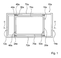
- FIG. 12 is a schematic top view of a neutralization device for neutralizing condensate 62 from a heater comprising a housing 10a having a condensate inlet 12a and a condensate outlet 14a.
- the neutralization device comprises an insert basket 16a which is intended for releasable insert is provided in the housing 10a and for receiving reactive, neutralizing agent forming constituents 20a.
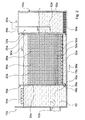
- the insert basket 16a is shown in an installed state in the housing 10a in an installed position and can be removed from the housing 10a by an operator together with the components 20a ( FIG. 2 ).
- the insert basket 16a forms in a main flow direction 88a of the condensate inlet 12a in the direction of the condensate outlet 14a of the condensate 62, a first partition wall 24a and a second partition wall 26a, which divides the housing 10a into different neutralization sections.
- the housing 10a has no partitions or is formed partition wall free.
- a capturing element 64a for unburned hydrocarbons is arranged, through which the hydrocarbons are taken up and / or decomposed with the aid of bacteria.
- the condensate 62 is guided from the first neutralization section in a bottom region thereof through a condensate inlet 48a of the insert basket 16a into a second neutralization section.
- the insert basket 16a has a condensate-permeable, sieve-like bottom 32a, through which the condensate 62 is guided into a receiving region 56a of the insert basket 16a, in which the components 20a are arranged.
- the bottom 32a is offset from the bottom edges of the partitions 24a, 26a, by means of which the insert basket 16a is raised on a bottom 78a of the housing 10a, viewed in an installed position offset upward, so that the bottom 32a of the insert basket 16a a distance from the bottom 78a of the housing 10a and the condensate 62 can advantageously flow over a large area through the bottom 32a of the insert basket 16a.
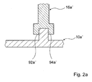
- a groove on the housing 10a in its bottom area is formed could also be on a housing 10a 'in the bottom region a web 92a' integrally formed, which engages in the mounted state in an insert basket 16a 'integrally formed groove 94a'.
- An undesired fouling of the groove arranged on the bottom portion of the housing 10a 'could be avoided and it could be an easy-to-clean groove 94a' on the insert basket 16a 'can be achieved (see. FIG. 2a ).
- the insert basket 16a can be embodied with a wall 58a, 60a which is adjustable in its position relative to the dividing walls 24a, 26a or with an adjustable bottom, as shown in FIG FIG. 2 indicated by dashed lines.
- one or more side walls of the insert basket 16a, in particular also the partitions 24a, 26a can be made adjustable in order to adjust a receiving area 56a with regard to its receiving volume. This can be achieved advantageously if the side walls and the bottom 32a of the insert basket 16a are connected by releasable plug connections.
- the condensate 62 is passed through the components 20a to a condensate outlet 52a of the insert basket 16a.
- the condensate inlet 48a and the condensate outlet 52a of the insert basket 16a are arranged at different heights, in order to achieve an advantageous flow through the receiving region 56a, namely from bottom to top. Further, a level difference of the condensate inlet 12a and the condensate outlet 52a achieves a siphon, thereby avoiding undesirable gas leakage from a boiler via a condensate line.
- the condensate 62 flows via the condensate outlet 52a into a third neutralization area, which is provided for depositing settling products 66a.
- the settling products 66a are formed in particular during the neutralization of the condensate 62.
- a further insert basket 68a could be provided, by means of which the settling products 66a could be taken out of the housing 10a together, without an operator coming into direct contact with the condensate 62 or the settling products 66a, as shown in FIG FIG. 2 indicated by dashed lines.
- the condensate 62 flows via the condensate outlet 14a.
- the condensate outlet 14a could basically be arranged at different heights, but not higher than the condensate outlet 52a.
- a pump 80a for pumping out the cleaned condensate 62, whereby the condensate 62 can be selectively removed in certain areas, as shown in FIG. 2 is shown in dashed lines.
- a level control unit 82a is preferably provided.
- the pump 80a may advantageously be arranged on a cover 84a.
- the insert basket 16a projects beyond a maximum condensate level height 90a or via a condensate overflow height determined by the condensate outlet 52a and forms a holding device for removal from the housing 10a above the condensate outlet 52a.
- the neutralization device has a guide unit 36a for guiding the insert basket 16a upon insertion into the housing 10a and on removal from the housing 10a.
- the guide unit 36a has on side walls 70a, 72a of the housing 10a and side walls 74a, 76a of the insert basket 16a and on the bottom 78a of the housing 10a spring groove connections, which are integrally formed integrally to the insert basket 16a and the other part to the housing 10a , In the bottom region of the housing 10a, the partitions 24a, 26a are respectively inserted between two webs formed on the housing 10a or in grooves formed thereby.
- the neutralization device In order to signal an operator a correct positioning of the insert basket 16a in the housing 10a and to avoid unwanted release of the insert basket 16a against a perpendicular to the bottom 32a of the insert basket 16a extending extension direction 86a from the housing 10a, the neutralization device has a locking connection having a fixing unit 40a on, in the bottom area in the guide unit 36 a, ie in the spring groove joints, is integrated.
- the neutralization device comprises a sealing unit 44a, which is provided for sealing between the housing 10a and the insert basket 16a and which is also integrated in the guide unit 36a, ie in the spring groove connections.
- the sealing unit 44a has elastic sealing means 46a, which are elastically deformed during the production of the spring groove connections and thus bring about a normal force on sealing surfaces.
- FIGS. 3 to 6 an alternative embodiment is shown. Substantially identical components, features and functions are basically numbered by the same reference numerals. To distinguish the embodiments, however, the reference numerals of the embodiments in the FIGS. 1 to 6 the letters a or b and so on are added. The following description is essentially limited to the differences from the embodiment in the FIGS. 1 and 2 , wherein with respect to the same components, features and functions on the description of the embodiment in the FIGS. 1 and 2 can be referenced.
- FIG. 3 shows an alternative neutralization device with two different, in a main flow direction 88b of a condensate 62 successively arranged insert baskets 16b, 18b.
- reactive components 20b are arranged, the components 20a of the embodiment in the FIGS. 1 and 2 while in the insert basket 18b, which also has a condensate inlet 50b and a condensate outlet 54b, different reactive constituents 22b, such as activated carbon elements or also ion exchangers, are arranged.
- the insert basket 18b also forms partitions 28b, 30b within the housing 10b, has a condensate-permeable bottom 34b and is guided by a guide unit 38b within the housing 10b is sealed with a sealing unit not shown relative to the housing 10b and by means of a fixing unit 42b in Housing 10b secured.
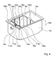
- FIG. 4 Fig. 10 shows a housing 10c, a partition wall 96c and an insert basket 16c of an alternative neutralization device having three neutralization sections 102c, 104c, 106c. Together with the housing 10c, the partition wall 96c forms the neutralization section 106c, which is disposed immediately adjacent to a condensate outlet 14c of the neutralizer.
- the partition wall 96c is formed integrally with the housing 10c and separated from the insert basket 16c, and separates the neutralization sections 106c from the neutralization section 104c.
- the insert basket 16c is arranged in the majority in the neutralization section 104c and forms a receiving region 56c through which condensate flows during an operation. In FIG. 4 the insert basket 16c is shown in an arrangement which it assumes during operation of the neutralization device.
- a wall 108c of the insert basket 16c has at its upper end a Kondensatauslass 54c, which is formed by a recess.
- the insert basket 16c has an extension 116c, which is formed as a channel, which has a groove-shaped depression 114c in an operating state of the neutralization device through which condensate flows from the receiving region 56c into the neutralization section 106c during operation of the neutralization device.
- the groove and thus the recess 114c opens into the condensate outlet 54c.
- the extension 116c protrudes in the operating state in the neutralization section 106c.
- the neutralization device has a sealing unit 98c which is fixed to the insert basket 16c and a gap 112c between a member 134c, namely the extension 116c, and the partition wall 96c seals.
- An elastic sealing means 118c of the sealing unit 98c which in an unassembled state has an oblong parallelepiped shape, is clamped in two gaps 120c formed by the insert basket 16c and, in the operating condition, abuts on an underside of the extension 116c, which is formed as a channel.
- the sealant 118c is in the operating state on an edge of the partition wall 96c and projects into the neutralization section 106c. This edge of the partition wall 96c surrounds a recess 110c of the partition wall 96c (FIG. FIG. 5 ) disposed at an upper end of the partition wall 96c in an operation of the neutralizer.
- the sealant 118c is in the operating state on the partition wall 96c such that during operation of the neutralization device, a flow of condensate from the neutralization section 106c between the sealant 118c and the extension 116c into the gap 112c and vice versa is prevented.
- the partition wall 96c seals the neutralization portions 106c and 104c against each other.
- a condensate level may reach up to a bottom of the extension 116c to ensure that condensation from the neutralization section 106c into the receiving area 56c is prevented from flowing.
- the neutralization section 106c captures heavy neutralization residues such as salts during operation of the neutralizer.
- reactive constituents are arranged in the insert basket 16c, which effect a displacement of a pH value of condensate flowing through the insert basket 16c in the direction of a neutral ph value.
- the ingredients are made of limestone.
- the constituents can also be formed from magnesium oxide or chlorine-containing substances.
- an up-floating layer formed of slag and at least partially made of salts may overflow into the neutralization section 106c where the salts settle to a bottom of the neutralization section 106c.
- the neutralization device has a barrier means 122c, which is provided to prevent a flow of the slag into the condensate outlet 14c during operation of the neutralization device ( FIGS. 4a . 4b and 4c ).
- the barrier means 122c is formed as a plug-in wall and inserted in an operating state in slots 124c of two walls of the housing 10c.
- the walls 126c, 128c are molded to the partition wall 96c and a wall 130c of the housing 10c having the condensate outlet 14c. Further, the walls 126c, 128c divide the neutralization section 106c into three parts.
- the slits 124c are disposed centrally in the walls 126c, 128c between the partition wall 96c and the wall 130c and also spaced from a bottom 132c of the housing 10c such that the barrier means 122c is spaced from the floor 132c in an engaged condition.
- the barrier means 122c, the partition wall 96c and the insert basket 16c have a substantially equal height on.
- the barrier means 122c is arranged between the trough-shaped extension 116c and the condensate outlet 14c. This means that a notional straight line having any point of the extension 116c and any point of the condensate outlet 14c will always intersect the barrier means 122c.
- condensate on a flow path 136c passes from the neutralization section 104c to the condensate outlet 14c.
- the condensate flowing from the neutralizing portion 104c into the neutralizing portion 106c flows below the barrier means 122c until it reaches the condensate outlet 14c and is allowed to flow out therefrom.
- Slag which also flows from the neutralization section 104c into the neutralization section 106c is thereby prevented from flowing out through the condensate outlet 14c by the barrier means 122c.
- soot and ash settle on a bottom of the neutralization section 102c.
- the neutralization device has a cover 100c ( FIG. 6 ), which is free of condensate line connections, allowing easy disassembly in particular the lid 100c can be achieved and in particular during maintenance of the neutralization device, in which the insert basket 16c is removed, disassembly of a condensate line connection can be avoided.
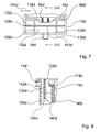
- FIGS. 7 to 9 an alternative embodiment of a neutralization device is shown.
- Substantially identical components, features and functions are basically numbered by the same reference numerals. To distinguish the embodiments, however, the reference numerals of the embodiment in the FIGS. 7 to 9 the letter d added.
- the following description is essentially limited to the differences from the embodiment in the FIGS. 4 to 6 , wherein with respect to the same components, features and functions on the description of the embodiment in the FIGS. 4 to 6 can be referenced.
- the in the FIGS. 7 to 9 illustrated neutralization device has slotless walls 126d, 128d.
- a barrier means 122d of the neutralizer has slots 138d.
- the slots 138d extend upward from an underside 140d of the barrier means 122d in a vertical direction.
- the walls 126d, 128d are disposed in the slots 138d.
- the barrier means 122d is fastened to the walls 126d, 128 in a form-fitting manner with respect to a longitudinal direction 144d.
- One side 142d of the barrier means 122d faces a condensate outlet 14d of the neutralizer.
Landscapes
- Life Sciences & Earth Sciences (AREA)
- Hydrology & Water Resources (AREA)
- Engineering & Computer Science (AREA)
- Environmental & Geological Engineering (AREA)
- Water Supply & Treatment (AREA)
- Chemical & Material Sciences (AREA)
- Organic Chemistry (AREA)
- Details Of Fluid Heaters (AREA)
- Physical Or Chemical Processes And Apparatus (AREA)
Applications Claiming Priority (1)
| Application Number | Priority Date | Filing Date | Title |
|---|---|---|---|
| DE200810019290 DE102008019290A1 (de) | 2008-04-16 | 2008-04-16 | Neutralisationsvorrichtung |
Publications (2)
| Publication Number | Publication Date |
|---|---|
| EP2110364A2 true EP2110364A2 (fr) | 2009-10-21 |
| EP2110364A3 EP2110364A3 (fr) | 2010-12-01 |
Family
ID=40874552
Family Applications (1)
| Application Number | Title | Priority Date | Filing Date |
|---|---|---|---|
| EP09001797A Withdrawn EP2110364A3 (fr) | 2008-04-16 | 2009-02-10 | Dispositif de neutralisation |
Country Status (2)
| Country | Link |
|---|---|
| EP (1) | EP2110364A3 (fr) |
| DE (1) | DE102008019290A1 (fr) |
Cited By (3)
| Publication number | Priority date | Publication date | Assignee | Title |
|---|---|---|---|---|
| GB2465662A (en) * | 2008-12-01 | 2010-06-02 | Sentinel Performance Solutions | Boiler condensate neutralising unit |
| EP2380853A3 (fr) * | 2010-04-20 | 2013-05-22 | Bomat Heiztechnik GmbH | Dispositif de neutralisation |
| EP3705806A4 (fr) * | 2017-11-02 | 2020-12-02 | Kyungdong Navien Co., Ltd. | Appareil de piégeage d'eau de condensat |
Citations (1)
| Publication number | Priority date | Publication date | Assignee | Title |
|---|---|---|---|---|
| EP1886721A2 (fr) | 2006-08-05 | 2008-02-13 | Bomat Heiztechnik GmbH | Dispositif de neutralisation de la condensation à partir d'un appareil de chauffage |
Family Cites Families (7)
| Publication number | Priority date | Publication date | Assignee | Title |
|---|---|---|---|---|
| DE3406097A1 (de) * | 1984-02-20 | 1985-08-29 | Krause, Willibald, 7317 Wendlingen | Vorrichtung zur neutralisation von sauren kondensaten |
| DE3540164A1 (de) * | 1985-11-13 | 1987-05-21 | Hermann Luebbers Gmbh | Filtervorrichtung fuer die neutralisation saurer kondensate aus abgasen |
| DE3838701A1 (de) * | 1988-11-15 | 1990-08-09 | Bernhard Kessel | Vorrichtung zum neutralisieren von fluessigkeiten |
| DE9202327U1 (de) * | 1992-02-22 | 1992-04-23 | Ullmann Plastic GmbH, 8765 Erlenbach | Neutralisationsgefäß für das Kondensat von Heizungsanlagen |
| AT403372B (de) * | 1996-01-30 | 1998-01-26 | Vaillant Gmbh | Neutralisationseinrichtung |
| DE10157156A1 (de) * | 2001-11-22 | 2003-05-28 | Freigeber Juergen | Filterelement zum Filtern und Neutralisierung von belastetem Kondensat/Wasser oder anderen Flüssigkeiten |
| EP1886974A3 (fr) * | 2006-07-31 | 2008-06-18 | Jürgen Freigeber | Dispositif de neutralisation de condensés de combustion acides |
-
2008
- 2008-04-16 DE DE200810019290 patent/DE102008019290A1/de not_active Withdrawn
-
2009
- 2009-02-10 EP EP09001797A patent/EP2110364A3/fr not_active Withdrawn
Patent Citations (1)
| Publication number | Priority date | Publication date | Assignee | Title |
|---|---|---|---|---|
| EP1886721A2 (fr) | 2006-08-05 | 2008-02-13 | Bomat Heiztechnik GmbH | Dispositif de neutralisation de la condensation à partir d'un appareil de chauffage |
Cited By (5)
| Publication number | Priority date | Publication date | Assignee | Title |
|---|---|---|---|---|
| GB2465662A (en) * | 2008-12-01 | 2010-06-02 | Sentinel Performance Solutions | Boiler condensate neutralising unit |
| GB2465662B (en) * | 2008-12-01 | 2013-08-14 | Sentinel Performance Solutions Ltd | Condensate unit |
| EP2380853A3 (fr) * | 2010-04-20 | 2013-05-22 | Bomat Heiztechnik GmbH | Dispositif de neutralisation |
| EP3705806A4 (fr) * | 2017-11-02 | 2020-12-02 | Kyungdong Navien Co., Ltd. | Appareil de piégeage d'eau de condensat |
| US11691900B2 (en) | 2017-11-02 | 2023-07-04 | Kyungdong Navien Co., Ltd. | Trap apparatus of condensate water |
Also Published As
| Publication number | Publication date |
|---|---|
| EP2110364A3 (fr) | 2010-12-01 |
| DE102008019290A1 (de) | 2009-10-22 |
Similar Documents
| Publication | Publication Date | Title |
|---|---|---|
| EP0319518B1 (fr) | Filtre à huile pour la purification d'huile de graissage | |
| EP3228376B1 (fr) | Module de filtration comprenant un élément de filtre et un cadre de fixation et installation de filtre à air comprenant un module de filtration | |
| EP2825707B1 (fr) | Dispositif anti-refoulement pour une douchette | |
| EP2845530B1 (fr) | Appareil d'aspiration portable pour liquides ou mélanges liquide/air | |
| WO2007042100A1 (fr) | Piece de montage pour sanitaire | |
| DE69824630T2 (de) | Filteranlage | |
| DE102017121209B4 (de) | Flächenreinigungsgerät | |
| EP3956611B1 (fr) | Dispositif de filtrage pour un dispositif d'extraction de fumées et dispositif d'extraction de fumées avec dispositif de filtrage | |
| DE102021001668A1 (de) | Filterpatrone und Wasserfiltervorrichtung | |
| DE102007033337C5 (de) | Filterkartusche für eine Wasserfiltervorrichtung | |
| DE102006038700A1 (de) | Vorrichtung zur Abscheidung von Flüssigkeiten aus Gasen | |
| DE2728137C2 (de) | Filtervorrichtung für industrielle Abwässer | |
| EP4259300A1 (fr) | Unité de filtre et unité de base d'un dispositif de séparation huile-eau pour éliminer des constituants contenant de l'huile d'un mélange huile-eau | |
| WO2016162087A1 (fr) | Pompe submersible à préfiltre | |
| EP0282906A2 (fr) | Séparateur de graisses | |
| DE102008019290A1 (de) | Neutralisationsvorrichtung | |
| DE102013002729A1 (de) | Druckluft-Wartungsgerät zum Filtern von Druckluft sowie Verfahren zum Wechseln einer Filterpatrone | |
| EP1454066A1 (fr) | Ensemble pompe submersible avec interrupteur a flotteur | |
| DE102006039952B4 (de) | Luftfilter | |
| EP3006636B1 (fr) | Évacuation murale avec pompe | |
| AT398752B (de) | Abscheider für leichtflüssigkeiten | |
| DE112009000298B4 (de) | Filtereinrichtung, insbesondere Luftfilter für Brennkraftmaschinen | |
| DE102015215595B4 (de) | Steckelement und Milchaufschäumeinrichtung | |
| DE29611960U1 (de) | Geruchverschluß | |
| DE102022120194B4 (de) | Dunstabzugsvorrichtung mit Reinigungsflüssigkeit |
Legal Events
| Date | Code | Title | Description |
|---|---|---|---|
| PUAI | Public reference made under article 153(3) epc to a published international application that has entered the european phase |
Free format text: ORIGINAL CODE: 0009012 |
|
| AK | Designated contracting states |
Kind code of ref document: A2 Designated state(s): AT BE BG CH CY CZ DE DK EE ES FI FR GB GR HR HU IE IS IT LI LT LU LV MC MK MT NL NO PL PT RO SE SI SK TR |
|
| AX | Request for extension of the european patent |
Extension state: AL BA RS |
|
| PUAL | Search report despatched |
Free format text: ORIGINAL CODE: 0009013 |
|
| AK | Designated contracting states |
Kind code of ref document: A3 Designated state(s): AT BE BG CH CY CZ DE DK EE ES FI FR GB GR HR HU IE IS IT LI LT LU LV MC MK MT NL NO PL PT RO SE SI SK TR |
|
| AX | Request for extension of the european patent |
Extension state: AL BA RS |
|
| AKY | No designation fees paid | ||
| REG | Reference to a national code |
Ref country code: DE Ref legal event code: R108 Effective date: 20110811 |
|
| STAA | Information on the status of an ep patent application or granted ep patent |
Free format text: STATUS: THE APPLICATION IS DEEMED TO BE WITHDRAWN |
|
| 18D | Application deemed to be withdrawn |
Effective date: 20110602 |