EP2110478B1 - Dispositif pour supporter un poteau - Google Patents
Dispositif pour supporter un poteau Download PDFInfo
- Publication number
- EP2110478B1 EP2110478B1 EP09005434A EP09005434A EP2110478B1 EP 2110478 B1 EP2110478 B1 EP 2110478B1 EP 09005434 A EP09005434 A EP 09005434A EP 09005434 A EP09005434 A EP 09005434A EP 2110478 B1 EP2110478 B1 EP 2110478B1
- Authority
- EP
- European Patent Office
- Prior art keywords
- pole
- clamping means
- socket
- chamber
- free end
- Prior art date
- Legal status (The legal status is an assumption and is not a legal conclusion. Google has not performed a legal analysis and makes no representation as to the accuracy of the status listed.)
- Active
Links
Images


Classifications
-
- E—FIXED CONSTRUCTIONS
- E04—BUILDING
- E04H—BUILDINGS OR LIKE STRUCTURES FOR PARTICULAR PURPOSES; SWIMMING OR SPLASH BATHS OR POOLS; MASTS; FENCING; TENTS OR CANOPIES, IN GENERAL
- E04H12/00—Towers; Masts or poles; Chimney stacks; Water-towers; Methods of erecting such structures
- E04H12/22—Sockets or holders for poles or posts
- E04H12/2253—Mounting poles or posts to the holder
- E04H12/2269—Mounting poles or posts to the holder in a socket
-
- E—FIXED CONSTRUCTIONS
- E01—CONSTRUCTION OF ROADS, RAILWAYS, OR BRIDGES
- E01F—ADDITIONAL WORK, SUCH AS EQUIPPING ROADS OR THE CONSTRUCTION OF PLATFORMS, HELICOPTER LANDING STAGES, SIGNS, SNOW FENCES, OR THE LIKE
- E01F9/00—Arrangement of road signs or traffic signals; Arrangements for enforcing caution
- E01F9/60—Upright bodies, e.g. marker posts or bollards; Supports for road signs
- E01F9/658—Upright bodies, e.g. marker posts or bollards; Supports for road signs characterised by means for fixing
- E01F9/673—Upright bodies, e.g. marker posts or bollards; Supports for road signs characterised by means for fixing for holding sign posts or the like
- E01F9/685—Subsoil means, e.g. foundations
Definitions
- This invention relates to a device for supporting a pole, more particularly to a holding system for use in such a device to releasably retain a pole in said device.
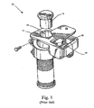
- the Applicant's UK patent GB 2 254 349 discloses a device 10 for supporting a pole, the device 10 comprising a housing 12 set into the ground to releasably receive a suitable pole, for example a signpost or a traffic bollard.
- the pole (a section of which is shown at 14) is placed within a chamber 16 in the housing 12, and is secured into place in the device 10 through the tightening of setscrews 18 against the pole 14 itself. Access to the setscrews 18 is provided via a side chamber 20 adjacent the chamber 16 for receipt of the pole 14.
- the device 10 also called a pole retention system
- the installation and removal of such poles at a site is greatly simplified, as it eliminates the need for the excavation and accurate vertical alignment necessary for traditional installation of a pole in the ground.
- One drawback of the device 10 is the relative inconvenience of access to the setscrews 18 through the side chamber 20. Access to the setscrews 18 may become obstructed through accumulation of detritus in the chamber 20, or the collection of run-off water in the chamber 20. In such cases, an operator may become inconvenienced when seeking to actuate the setscrews 18 in order to retain or release a pole.
- DE225200-C , US2006/0137287-A1 , DE2021735-U1 , DE2133278-A1 and US1388268-A1 each disclose a socket for a pole, post or tube, in which an actuating mechanism is accessible to a user to actuate a locking mechanism disposed in a chamber adjacent to the socket receiving a pole, to thereby engage and lock in place a pole in said socket.
- a device for supporting a pole comprising:
- actuating member in an access port open to the top surface allows for easier operation of the device. As the member is directly accessible from the top surface of the device, this allows for easier actuation of the locking mechanism. Also, as only the member is directly accessible from the top surface, there is less chance of the collection of debris within the chamber, which may affect the operation of the device.
- said member is operable to act on said clamping means to advance said clamping means into the interior of said socket to receive a pole, said clamping means retaining a pole within said socket.
- said device further comprises a resilient biasing means provided in said chamber, said resilient biasing means acting on said clamping means to bias said clamping means away from the interior of said socket to receive a pole.
- resilient biasing means to bias the clamping means away from the socket allows for the releasable retention of poles within the device socket, as the clamping means is brought out of contact with a pole within the socket as the actuating member is retracted, due to the biasing action of the biasing means.
- said resilient biasing means comprises a helical spring.
- said resilient biasing means comprises a conical spring.
- said clamping means comprises a locating member projecting from said clamping means, said resilient biasing means coupled with said locating member.
- the use of the locating member prevents the biasing means from becoming dislodged from the clamping means during use.
- said actuating member is further operable to retract said clamping means from the interior of said socket to receive a pole.
- This configuration allows for the actuating member to selectively advance or retract said clamping means into the socket, allowing for the clamping means to releasably retain a pole within said socket.
- Such selective advancing and retracting may be accomplished through use of, for example, a rack and pinion mechanism.
- said clamping means are pivotably mounted within said chamber.
- said device further comprises a pivot provided within said chamber, said clamping means pivotably mounted on said pivot.
- said clamping means comprises a pair of projecting members.
- said first free end of said clamp body is formed by a plurality of projecting members, said projecting members operable to advance into the interior of said socket to receive a pole.
- the actuating member comprises a threaded bolt.
- the clamping means comprises a threaded pin coupled to said threaded bolt.
- a device for supporting a pole is indicated generally at 30.
- the device 30 comprises a body 32 having a first top surface 33, which is exposed when the device 30 is installed for use located substantially beneath the surface of the ground, with the top surface 33 exposed.
- the body 32 has a chamber 34 defined therein, chamber 34 having an opening defined in said first surface 33.
- Chamber 34 acts to receive a post or a pole to be supported within the device 30.
- the chamber 34 has a square cross-section, to receive a post having a similarly dimensioned cross-section.
- the device 30 may have a chamber 34 having a differently-shaped cross-section, e.g. circular, in order to accommodate poles or posts of various cross-section shapes.
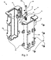
- the body 32 of the device 30 is shown as formed from two separate symmetrical halves 32a,32b, which are secured together using suitable bolts 36 acting as bolting means applied to appropriate eyes 38 acting as receiving means located at various positions around the edges of the halves 32a,32b of the body 32 of the device 30.
- suitable bolts 36 acting as bolting means applied to appropriate eyes 38 acting as receiving means located at various positions around the edges of the halves 32a,32b of the body 32 of the device 30 may be integrally formed from a single piece of material e.g. cast metal.
- a plurality of coupling ports 40 are located on the exterior surface of the lower portion of the device body 32.
- Said coupling ports 40 may be coupled with suitable anchoring means (not shown) to secure the device in place beneath the surface, for example within a concrete foundation, with the coupling ports 40 secured to sections of a reinforcing steel mesh within the foundation. It will be understood that said coupling ports 40 are optionally provided on the device body 32.
- a pole or post
- the pole is releasably retained in place by a holding system acting on the surface of the pole.
- the holding system 42 is contained in a side housing 44, located adjacent the pole-receiving chamber 34. Actuation of the holding system 42 is achieved via an access port 46, defined in the first top surface 33 of the device body 32, said access port 46 located adjacent the opening of said chamber 34.
- Fig. 3 is an exploded view of the device 30 of Fig. 2
- Fig. 4 shows in cross-section an implementation of the holding system 42 in an alternative pole retention device to device 30 (for ease of understanding, the same terms and reference numerals are used for both devices).
- chamber 34 is of a shallower depth than in the device of Fig. 3 . Otherwise all feature of the device of Fig. 4 are the same as the device of Fig. 3 . Also, it will be understood that chamber 34 may be replaced with a through-going aperture.
- antechamber 48 is provided in housing 44, the antechamber 48 having an opening 48a into an interior surface 34a of pole-receiving chamber 34.
- Access port 46 extends through said housing 44, extending from a first end 46a at said first top surface 33 of the device 30 to a second end 46b opening into said antechamber 48.
- a clamp 50 is pivotably mounted within said antechamber 48, on pivot 52.
- Pivot 52 is arranged transverse to the housing 44 such that the axis of the pivot 52 is parallel to the interior surface 34a of the chamber 34 and to the first top surface 33 of the device body 32.
- the pivot 52 is located towards the opening 48a of the antechamber 48, adjacent the pole-receiving chamber 34.
- said clamp 50 may comprise a pair of circular projections 53 on opposite side of said clamp 50, said projections 53 being received in corresponding apertures 55 on opposed sides of antechamber 48.
- the projections 53 allow for the clamp 50 to pivot within the antechamber 48.
- Clamp 50 is substantially L-shaped, with the pivot point located such that the free end of the relatively shorter first portion 50a of the clamp 50 is operable to pivot from the interior of the antechamber 48 into the interior of the pole-receiving chamber 34.
- the relatively longer second portion 50b of the clamp 50 extends away from said opening 48a of said antechamber 48, towards said second end 46b of said access port 46.
- helical spring 54 acts as resilient biasing means and is located in said antechamber 48, positioned substantially beneath the second end 46b of said access port 46.
- the spring 54 is arranged such that a first end 54a of said biasing means 54 bears upon the base of said antechamber 48 opposite said second end 46b of said access port 46, and a second end 54b of said biasing means 54 bears upon the free end of said relatively longer second portion 50b of said clamp 50.
- the biasing means 54 biases the free end of said relatively longer second portion 50b of said clamp 50 is forced towards said second end 46b of said access port 46.
- said clamp 50 may be provided with a locating member 56 projecting from the underside of the free end of said relatively longer second portion 50b, said locating member 56 coupling with the first end 54a of said biasing means 54.
- the locating member 56 acts to prevent said biasing means 54 from becoming dislodged from its position acting on the second portion 50b of said clamp.
- the devices may further comprise a receiving channel 58 defined in the wall of said antechamber 48 opposite said second end 46b of said access port 46.
- the receiving channel 58 accommodates said first end 54a of said biasing means 54, and prevents movement or buckling of said biasing means 54 within said antechamber 48 while also providing a recess to contain said biasing means 54 when compressed.
- the helical spring illustrated as biasing means 54 may be replaced by a conical spring, which has a smaller solid height due to telescoping, and which therefore does not require use of the receiving channel 58 to contain the spring when compressed and is less prone to buckling.
- a threaded bolt 60 acting as a tightening means is located within said access port 46.
- the bolt 60 comprises a head end 60a and a bearing end 60b, the head of said bolt 60 (at said head end 60a) being exposed at the first end 46a of said access port 46.
- the head 60a is generally provided parallel to and below the top surface 33 of the device. This arrangement of the bolt head 60a means that the bolt head 60a is presented in an easily accessible position, which does not require a relatively complicated operation to actuate.
- the bolt 60 is threaded through a retaining nut 62, said nut 62 maintained in position within said access port 46 by shoulder projections 64 projecting from the walls of said access port 46 directly above and below said nut 62.
- said retaining nut 62 may be replaced by a suitably threaded portion integrally formed in the body of the device.
- said bolt 60 extends through said nut 62 to the second end 46b of said access port 46, where it can be seen that said bearing end 60b of said bolt 60 bears against the free end of said relatively longer second portion 50b of said clamp 50, substantially opposite said locating member 56.
- the head of said bolt 60 is arranged to receive a tool (screw driver, Allen key, etc.) to tighten or loosen said threaded bolt 60 within said retaining nut 62, and thereby advance said bolt 60 within said access port 46.
- a cover 66 for said access port 46 is provided on said top surface 33, to prevent the accumulation of debris within the access port 46. Said cover 66 may also be lockable, to prevent unauthorised access to the holding system.
- the clamp 50 is initially in its at rest position, as indicated in Fig. 4 , with said free end of said first portion 50a contained within said antechamber 48, said bolt 60 completely contained within said access port 46, and said free end of said second portion 50b of said clamp 50 abutting said bearing end 60b of said bolt 60.
- the lower end of a pole to be installed (not shown) is then positioned within the device chamber 34.
- the holding system 42 is actuated by applying a screwing motion to the head of said bolt 60 (through use of an appropriate tool, as described above).
- the bearing end 60b of said bolt 60 acts on the free end of the second portion 50b of said clamp 50, forcing the free end of the second portion 50b away from said access port 46 and compressing said biasing means 54.
- the free end of the first clamp portion 50a is consequently pivoted in the direction of the chamber 34 (as indicated by the arrow), the free end acting to bear against the surface of the contained pole.
- the holding system 42 may be employed.
- a rack-and-pinion mechanism may be used, wherein a first end of a rack is accessible at said top surface 33 of the device body 32.
- the clamp 50 further comprises a toothed pinion section provided at the free end 50b of the clamp 50, said pinion section coupled with said rack.
- the clamp 50 is pivoted within the device housing, such that the first end 50a of the clamp is advanced or retracted relative to the pole-receiving chamber 34, allowing for a pole to be releasably retained within the chamber 34.
- a threaded pin may be provided within the free end 50b of the clamp 50, the threaded pin coupled with said threaded bolt 60.
- the threaded pin will travel along the length of the bolt 60, coupling the clamp 50 with the bolt 60.
- free end 50a or bearing face of the clamp 50 may be formed as two or more separate fingers, which would either bear directly on a pole within chamber 34 at two or more locations, or bear on a pad (or a plurality of pads), which then act on the contained pole.
- the free end 50a or bearing face of the clamp 50 may be toothed.
Landscapes
- Engineering & Computer Science (AREA)
- Architecture (AREA)
- Civil Engineering (AREA)
- Structural Engineering (AREA)
- Tables And Desks Characterized By Structural Shape (AREA)
- Tents Or Canopies (AREA)
- Clamps And Clips (AREA)
- Refuge Islands, Traffic Blockers, Or Guard Fence (AREA)
Claims (13)
- Dispositif (30) destiné à supporter un poteau, comportant :un logement (32) ayant une surface supérieure (33) et une douille (34) définie à l'intérieur du logement (32) ; ladite douille (34) étant ouverte au niveau de la surface supérieure à des fins de réception d'une extrémité d'un poteau ;un moyen de serrage (50, 52, 53) disposé dans une chambre (44) de manière adjacente par rapport à ladite douille (34) et servant à des fins de mise en prise d'un poteau dans ladite douille (34) pour de ce fait verrouiller le poteau en place dans la douille (34) ;un orifice d'accès (46) ouvert au niveau de la surface supérieure et ayant dans celui-ci un élément d'actionnement (60, 62), ledit élément étant présenté au niveau de la surface supérieure à des fins d'actionnement par un utilisateur, ledit élément (60, 62) coopérant avec ledit moyen de serrage (50, 52, 53) pour permettre audit utilisateur d'effectuer la mise en prise du moyen de serrage en actionnant ledit élément (60, 62) ;caractérisé en ce que :ledit moyen de serrage (50, 52, 53) comporte un corps de serrage sensiblement en forme de L (50), dans lequel une première extrémité libre (50a) dudit corps de serrage sert à des fins d'avance dans l'intérieur de ladite douille (34) à des fins de réception d'un poteau, ladite première extrémité libre (50a) agissant sur une surface dudit poteau reçu afin de retenir ledit poteau à l'intérieur de ladite douille (34) ; et dans lequel ledit élément d'actionnement (60, 62) agit sur une seconde extrémité libre (50b) dudit corps de serrage (50).
- Dispositif (30) selon la revendication 1, dans lequel ledit élément d'actionnement (60, 62) sert à agir sur ledit moyen de serrage (50, 52, 53) à des fins d'avance dudit moyen de serrage dans l'intérieur de ladite douille (34) pour recevoir un poteau, ledit moyen de serrage (50, 52, 53) étant adapté pour retenir un poteau à l'intérieur de ladite douille (34).
- Dispositif selon la revendication 2, ledit dispositif comportant par ailleurs un moyen de sollicitation élastique (54) mis en oeuvre dans ladite chambre (44), ledit moyen de sollicitation élastique (54) agissant sur ledit moyen de serrage (50, 52, 53) pour solliciter ledit moyen de serrage à l'opposé de l'intérieur de ladite douille (34) pour recevoir un poteau.
- Dispositif selon la revendication 3, dans lequel ledit moyen de sollicitation élastique (54) est sélectionné parmi l'un de : un ressort hélicoïdal ; ou un ressort conique.
- Dispositif selon la revendication 3 ou la revendication 4, ledit dispositif comportant par ailleurs un élément de positionnement (56) faisant saillie en provenance dudit moyen de serrage (50), ledit moyen de sollicitation élastique (54) étant accouplé audit élément de positionnement pour retenir ledit moyen de sollicitation par rapport audit moyen de serrage.
- Dispositif selon la revendication 2, dans lequel ledit élément d'actionnement (60, 62) sert par ailleurs à escamoter ledit moyen de serrage (50) en provenance de l'intérieur de ladite douille (34) pour recevoir un poteau.
- Dispositif selon la revendication 6, dans lequel ledit élément d'actionnement (60, 62) et ledit moyen de serrage (50) forment un mécanisme à pignon et crémaillère.
- Dispositif selon l'une quelconque des revendications 1 à 7, dans lequel ledit moyen de serrage (50) est monté de manière pivotante à l'intérieur de ladite chambre (44).
- Dispositif selon la revendication 8, dans lequel ledit dispositif comporte par ailleurs un pivot (55) mis en oeuvre à l'intérieur de ladite chambre (44) ; ledit moyen de serrage (50) étant monté de manière pivotante sur ledit pivot.
- Dispositif selon la revendication 1, dans lequel ladite première extrémité libre (50a) dudit corps de serrage (50) est formée par une pluralité d'éléments faisant saillie, lesdits éléments faisant saillie servant à des fins d'avance dans l'intérieur de ladite douille pour recevoir un poteau.
- Dispositif selon l'une quelconque des revendications 1 à 9, dans lequel ledit moyen de serrage (50, 52, 53) comporte une paire d'éléments faisant saillie (53).
- Dispositif selon l'une quelconque des revendications précédentes, dans lequel l'élément d'actionnement (60) comporte un boulon fileté (60).
- Dispositif selon la revendication 12, dans lequel le moyen de serrage (50, 52, 53) comporte une goupille filetée accouplée audit boulon fileté.
Priority Applications (1)
| Application Number | Priority Date | Filing Date | Title |
|---|---|---|---|
| PL09005434T PL2110478T3 (pl) | 2008-04-18 | 2009-04-16 | Urządzenie podtrzymujące słup |
Applications Claiming Priority (1)
| Application Number | Priority Date | Filing Date | Title |
|---|---|---|---|
| IE20080304 | 2008-04-18 |
Publications (3)
| Publication Number | Publication Date |
|---|---|
| EP2110478A2 EP2110478A2 (fr) | 2009-10-21 |
| EP2110478A3 EP2110478A3 (fr) | 2011-04-13 |
| EP2110478B1 true EP2110478B1 (fr) | 2012-09-26 |
Family
ID=40848679
Family Applications (1)
| Application Number | Title | Priority Date | Filing Date |
|---|---|---|---|
| EP09005434A Active EP2110478B1 (fr) | 2008-04-18 | 2009-04-16 | Dispositif pour supporter un poteau |
Country Status (2)
| Country | Link |
|---|---|
| EP (1) | EP2110478B1 (fr) |
| PL (1) | PL2110478T3 (fr) |
Families Citing this family (7)
| Publication number | Priority date | Publication date | Assignee | Title |
|---|---|---|---|---|
| US9376831B2 (en) | 2011-01-28 | 2016-06-28 | Unimi Solutions Ab | Foundation system for charging poles |
| GB2522121A (en) * | 2013-12-13 | 2015-07-15 | Innovative Products Ltd | A post protection system |
| GB2534354A (en) * | 2015-01-08 | 2016-07-27 | Savage Peter Ltd | Support |
| GB2579831B (en) | 2018-12-17 | 2022-02-02 | Simbars Uk Ltd | A post socket |
| EP4368779A1 (fr) | 2022-11-10 | 2024-05-15 | NAL Products Limited | Prise universelle de contact avec le sol |
| USD1117059S1 (en) * | 2022-11-15 | 2026-03-10 | Nal Products Limited | Ground engaging socket assembly |
| GB2631318A (en) * | 2023-06-28 | 2025-01-01 | Simbars Uk Ltd | A post socket |
Family Cites Families (6)
| Publication number | Priority date | Publication date | Assignee | Title |
|---|---|---|---|---|
| DE225200C (fr) * | ||||
| US1388268A (en) * | 1919-08-25 | 1921-08-23 | Rowe Mfg Co | Coupling |
| DE2133278A1 (de) * | 1971-07-05 | 1973-01-18 | Konrad Nitsche | Bodenhuelse fuer pfaehle |
| IE65270B1 (en) * | 1991-03-14 | 1995-10-18 | Square Systems Ltd | Device for supporting a pole |
| DE20217345U1 (de) * | 2002-11-11 | 2003-01-09 | Krinner Innovation GmbH, 94342 Straßkirchen | Befestigungsvorrichtung zur ausrichtbaren Halterung eines stabförmigen Gegenstandes |
| US7543415B2 (en) * | 2004-12-19 | 2009-06-09 | S.R. Smith, Llc | Starting platform wedge assembly |
-
2009
- 2009-04-16 PL PL09005434T patent/PL2110478T3/pl unknown
- 2009-04-16 EP EP09005434A patent/EP2110478B1/fr active Active
Also Published As
| Publication number | Publication date |
|---|---|
| EP2110478A2 (fr) | 2009-10-21 |
| EP2110478A3 (fr) | 2011-04-13 |
| PL2110478T3 (pl) | 2013-03-29 |
Similar Documents
| Publication | Publication Date | Title |
|---|---|---|
| EP2110478B1 (fr) | Dispositif pour supporter un poteau | |
| KR100590910B1 (ko) | 잠금장치가 구비된 맨홀 | |
| US5836625A (en) | Bolt housing, assembly, and fitted panel | |
| JP2835946B2 (ja) | 共同溝等の蓋体のロック装置 | |
| DE19939628A1 (de) | Verschlußvorrichtung für einen Schacht | |
| CN111636486A (zh) | 一种水利工程井口防护结构 | |
| KR100930106B1 (ko) | 잠금장치를 구비한 맨홀뚜껑 | |
| GB2297781A (en) | Retractable post assembly | |
| US4281524A (en) | Key-controlled lock for a barrier cable | |
| JP2957962B2 (ja) | グレーチングのヒンジ機構 | |
| KR100300737B1 (ko) | 이탈방지장치가 설치된 맨홀 | |
| CN219840479U (zh) | 一种工地防护栏 | |
| KR20100002884U (ko) | 잠금 및 도난방지 기능을 갖는 스틸그레이팅 | |
| US6676465B2 (en) | Locking device for outboard motor | |
| KR200192124Y1 (ko) | 잠금장치 장착형 맨홀 덮개 | |
| KR200276200Y1 (ko) | 밸브 개폐용 조작대 | |
| DE202019103833U1 (de) | Diebstahlsicherung für Surfbrett | |
| EP1820752B1 (fr) | Dispositif de fixation destiné à la fixation d'un récipient de collecte sur un profil rond et/ou anguleux ou sur une paroi | |
| DE102010039944B3 (de) | Haltevorrichtung | |
| CN212866060U (zh) | 一种用于缆线铺设的窨井通道的防盗窨井盖套件 | |
| JPH0629407Y2 (ja) | グレーチング蓋用施錠装置 | |
| JPS5920435Y2 (ja) | マンホ−ル蓋の施錠装置 | |
| EP1221405A2 (fr) | Support de bicyclette | |
| JP2013060753A (ja) | 防護柵 | |
| JP3938330B2 (ja) | マンホール蓋装置のロック構造 |
Legal Events
| Date | Code | Title | Description |
|---|---|---|---|
| PUAI | Public reference made under article 153(3) epc to a published international application that has entered the european phase |
Free format text: ORIGINAL CODE: 0009012 |
|
| AK | Designated contracting states |
Kind code of ref document: A2 Designated state(s): AT BE BG CH CY CZ DE DK EE ES FI FR GB GR HR HU IE IS IT LI LT LU LV MC MK MT NL NO PL PT RO SE SI SK TR |
|
| PUAL | Search report despatched |
Free format text: ORIGINAL CODE: 0009013 |
|
| AK | Designated contracting states |
Kind code of ref document: A3 Designated state(s): AT BE BG CH CY CZ DE DK EE ES FI FR GB GR HR HU IE IS IT LI LT LU LV MC MK MT NL NO PL PT RO SE SI SK TR |
|
| AX | Request for extension of the european patent |
Extension state: AL BA RS |
|
| 17P | Request for examination filed |
Effective date: 20111013 |
|
| GRAP | Despatch of communication of intention to grant a patent |
Free format text: ORIGINAL CODE: EPIDOSNIGR1 |
|
| GRAS | Grant fee paid |
Free format text: ORIGINAL CODE: EPIDOSNIGR3 |
|
| GRAA | (expected) grant |
Free format text: ORIGINAL CODE: 0009210 |
|
| AK | Designated contracting states |
Kind code of ref document: B1 Designated state(s): AT BE BG CH CY CZ DE DK EE ES FI FR GB GR HR HU IE IS IT LI LT LU LV MC MK MT NL NO PL PT RO SE SI SK TR |
|
| REG | Reference to a national code |
Ref country code: GB Ref legal event code: FG4D |
|
| REG | Reference to a national code |
Ref country code: CH Ref legal event code: EP |
|
| REG | Reference to a national code |
Ref country code: AT Ref legal event code: REF Ref document number: 577140 Country of ref document: AT Kind code of ref document: T Effective date: 20121015 |
|
| REG | Reference to a national code |
Ref country code: IE Ref legal event code: FG4D |
|
| REG | Reference to a national code |
Ref country code: DE Ref legal event code: R096 Ref document number: 602009009938 Country of ref document: DE Effective date: 20121122 |
|
| PG25 | Lapsed in a contracting state [announced via postgrant information from national office to epo] |
Ref country code: LT Free format text: LAPSE BECAUSE OF FAILURE TO SUBMIT A TRANSLATION OF THE DESCRIPTION OR TO PAY THE FEE WITHIN THE PRESCRIBED TIME-LIMIT Effective date: 20120926 Ref country code: FI Free format text: LAPSE BECAUSE OF FAILURE TO SUBMIT A TRANSLATION OF THE DESCRIPTION OR TO PAY THE FEE WITHIN THE PRESCRIBED TIME-LIMIT Effective date: 20120926 Ref country code: HR Free format text: LAPSE BECAUSE OF FAILURE TO SUBMIT A TRANSLATION OF THE DESCRIPTION OR TO PAY THE FEE WITHIN THE PRESCRIBED TIME-LIMIT Effective date: 20120926 Ref country code: NO Free format text: LAPSE BECAUSE OF FAILURE TO SUBMIT A TRANSLATION OF THE DESCRIPTION OR TO PAY THE FEE WITHIN THE PRESCRIBED TIME-LIMIT Effective date: 20121226 |
|
| REG | Reference to a national code |
Ref country code: NL Ref legal event code: T3 |
|
| REG | Reference to a national code |
Ref country code: AT Ref legal event code: MK05 Ref document number: 577140 Country of ref document: AT Kind code of ref document: T Effective date: 20120926 |
|
| REG | Reference to a national code |
Ref country code: LT Ref legal event code: MG4D Effective date: 20120926 |
|
| PG25 | Lapsed in a contracting state [announced via postgrant information from national office to epo] |
Ref country code: SI Free format text: LAPSE BECAUSE OF FAILURE TO SUBMIT A TRANSLATION OF THE DESCRIPTION OR TO PAY THE FEE WITHIN THE PRESCRIBED TIME-LIMIT Effective date: 20120926 Ref country code: LV Free format text: LAPSE BECAUSE OF FAILURE TO SUBMIT A TRANSLATION OF THE DESCRIPTION OR TO PAY THE FEE WITHIN THE PRESCRIBED TIME-LIMIT Effective date: 20120926 Ref country code: GR Free format text: LAPSE BECAUSE OF FAILURE TO SUBMIT A TRANSLATION OF THE DESCRIPTION OR TO PAY THE FEE WITHIN THE PRESCRIBED TIME-LIMIT Effective date: 20121227 Ref country code: SE Free format text: LAPSE BECAUSE OF FAILURE TO SUBMIT A TRANSLATION OF THE DESCRIPTION OR TO PAY THE FEE WITHIN THE PRESCRIBED TIME-LIMIT Effective date: 20120926 |
|
| REG | Reference to a national code |
Ref country code: PL Ref legal event code: T3 |
|
| PG25 | Lapsed in a contracting state [announced via postgrant information from national office to epo] |
Ref country code: RO Free format text: LAPSE BECAUSE OF FAILURE TO SUBMIT A TRANSLATION OF THE DESCRIPTION OR TO PAY THE FEE WITHIN THE PRESCRIBED TIME-LIMIT Effective date: 20120926 Ref country code: ES Free format text: LAPSE BECAUSE OF FAILURE TO SUBMIT A TRANSLATION OF THE DESCRIPTION OR TO PAY THE FEE WITHIN THE PRESCRIBED TIME-LIMIT Effective date: 20130106 Ref country code: EE Free format text: LAPSE BECAUSE OF FAILURE TO SUBMIT A TRANSLATION OF THE DESCRIPTION OR TO PAY THE FEE WITHIN THE PRESCRIBED TIME-LIMIT Effective date: 20120926 Ref country code: CZ Free format text: LAPSE BECAUSE OF FAILURE TO SUBMIT A TRANSLATION OF THE DESCRIPTION OR TO PAY THE FEE WITHIN THE PRESCRIBED TIME-LIMIT Effective date: 20120926 Ref country code: IS Free format text: LAPSE BECAUSE OF FAILURE TO SUBMIT A TRANSLATION OF THE DESCRIPTION OR TO PAY THE FEE WITHIN THE PRESCRIBED TIME-LIMIT Effective date: 20130126 |
|
| PG25 | Lapsed in a contracting state [announced via postgrant information from national office to epo] |
Ref country code: SK Free format text: LAPSE BECAUSE OF FAILURE TO SUBMIT A TRANSLATION OF THE DESCRIPTION OR TO PAY THE FEE WITHIN THE PRESCRIBED TIME-LIMIT Effective date: 20120926 Ref country code: CY Free format text: LAPSE BECAUSE OF FAILURE TO SUBMIT A TRANSLATION OF THE DESCRIPTION OR TO PAY THE FEE WITHIN THE PRESCRIBED TIME-LIMIT Effective date: 20120926 Ref country code: PT Free format text: LAPSE BECAUSE OF FAILURE TO SUBMIT A TRANSLATION OF THE DESCRIPTION OR TO PAY THE FEE WITHIN THE PRESCRIBED TIME-LIMIT Effective date: 20130128 |
|
| PG25 | Lapsed in a contracting state [announced via postgrant information from national office to epo] |
Ref country code: AT Free format text: LAPSE BECAUSE OF FAILURE TO SUBMIT A TRANSLATION OF THE DESCRIPTION OR TO PAY THE FEE WITHIN THE PRESCRIBED TIME-LIMIT Effective date: 20120926 |
|
| PG25 | Lapsed in a contracting state [announced via postgrant information from national office to epo] |
Ref country code: BG Free format text: LAPSE BECAUSE OF FAILURE TO SUBMIT A TRANSLATION OF THE DESCRIPTION OR TO PAY THE FEE WITHIN THE PRESCRIBED TIME-LIMIT Effective date: 20121226 Ref country code: DK Free format text: LAPSE BECAUSE OF FAILURE TO SUBMIT A TRANSLATION OF THE DESCRIPTION OR TO PAY THE FEE WITHIN THE PRESCRIBED TIME-LIMIT Effective date: 20120926 |
|
| PLBE | No opposition filed within time limit |
Free format text: ORIGINAL CODE: 0009261 |
|
| STAA | Information on the status of an ep patent application or granted ep patent |
Free format text: STATUS: NO OPPOSITION FILED WITHIN TIME LIMIT |
|
| PG25 | Lapsed in a contracting state [announced via postgrant information from national office to epo] |
Ref country code: IT Free format text: LAPSE BECAUSE OF FAILURE TO SUBMIT A TRANSLATION OF THE DESCRIPTION OR TO PAY THE FEE WITHIN THE PRESCRIBED TIME-LIMIT Effective date: 20120926 |
|
| 26N | No opposition filed |
Effective date: 20130627 |
|
| REG | Reference to a national code |
Ref country code: DE Ref legal event code: R097 Ref document number: 602009009938 Country of ref document: DE Effective date: 20130627 |
|
| PG25 | Lapsed in a contracting state [announced via postgrant information from national office to epo] |
Ref country code: MC Free format text: LAPSE BECAUSE OF FAILURE TO SUBMIT A TRANSLATION OF THE DESCRIPTION OR TO PAY THE FEE WITHIN THE PRESCRIBED TIME-LIMIT Effective date: 20120926 |
|
| REG | Reference to a national code |
Ref country code: CH Ref legal event code: PL |
|
| PG25 | Lapsed in a contracting state [announced via postgrant information from national office to epo] |
Ref country code: CH Free format text: LAPSE BECAUSE OF NON-PAYMENT OF DUE FEES Effective date: 20130430 Ref country code: LI Free format text: LAPSE BECAUSE OF NON-PAYMENT OF DUE FEES Effective date: 20130430 |
|
| PG25 | Lapsed in a contracting state [announced via postgrant information from national office to epo] |
Ref country code: MT Free format text: LAPSE BECAUSE OF FAILURE TO SUBMIT A TRANSLATION OF THE DESCRIPTION OR TO PAY THE FEE WITHIN THE PRESCRIBED TIME-LIMIT Effective date: 20120926 |
|
| PG25 | Lapsed in a contracting state [announced via postgrant information from national office to epo] |
Ref country code: TR Free format text: LAPSE BECAUSE OF FAILURE TO SUBMIT A TRANSLATION OF THE DESCRIPTION OR TO PAY THE FEE WITHIN THE PRESCRIBED TIME-LIMIT Effective date: 20120926 |
|
| PG25 | Lapsed in a contracting state [announced via postgrant information from national office to epo] |
Ref country code: LU Free format text: LAPSE BECAUSE OF NON-PAYMENT OF DUE FEES Effective date: 20130416 Ref country code: MK Free format text: LAPSE BECAUSE OF FAILURE TO SUBMIT A TRANSLATION OF THE DESCRIPTION OR TO PAY THE FEE WITHIN THE PRESCRIBED TIME-LIMIT Effective date: 20120926 Ref country code: HU Free format text: LAPSE BECAUSE OF FAILURE TO SUBMIT A TRANSLATION OF THE DESCRIPTION OR TO PAY THE FEE WITHIN THE PRESCRIBED TIME-LIMIT; INVALID AB INITIO Effective date: 20090416 |
|
| REG | Reference to a national code |
Ref country code: FR Ref legal event code: PLFP Year of fee payment: 8 |
|
| REG | Reference to a national code |
Ref country code: FR Ref legal event code: PLFP Year of fee payment: 9 |
|
| REG | Reference to a national code |
Ref country code: FR Ref legal event code: PLFP Year of fee payment: 10 |
|
| REG | Reference to a national code |
Ref country code: DE Ref legal event code: R081 Ref document number: 602009009938 Country of ref document: DE Owner name: NAL PRODUCTS LTD., IE Free format text: FORMER OWNER: SQUARE SYSTEMS LTD., DROGHEDA, COUNTY LOUTH, IE Ref country code: DE Ref legal event code: R081 Ref document number: 602009009938 Country of ref document: DE Owner name: INNOVATIVE PRODUCTS LTD., IE Free format text: FORMER OWNER: SQUARE SYSTEMS LTD., DROGHEDA, COUNTY LOUTH, IE |
|
| REG | Reference to a national code |
Ref country code: GB Ref legal event code: 732E Free format text: REGISTERED BETWEEN 20220428 AND 20220504 |
|
| REG | Reference to a national code |
Ref country code: NL Ref legal event code: PD Owner name: INNOVATIVE PRODUCTS LIMITED; IE Free format text: DETAILS ASSIGNMENT: CHANGE OF OWNER(S), ASSIGNMENT; FORMER OWNER NAME: SQUARE SYSTEMS LIMITED Effective date: 20220616 |
|
| REG | Reference to a national code |
Ref country code: BE Ref legal event code: PD Owner name: INNOVATIVE PRODUCTS LIMITED; IE Free format text: DETAILS ASSIGNMENT: CHANGE OF OWNER(S), ASSIGNMENT; FORMER OWNER NAME: SQUARE SYSTEMS LIMITED Effective date: 20220601 |
|
| REG | Reference to a national code |
Ref country code: DE Ref legal event code: R081 Ref document number: 602009009938 Country of ref document: DE Owner name: NAL PRODUCTS LTD., IE Free format text: FORMER OWNER: INNOVATIVE PRODUCTS LTD., DROGHEDA, IE |
|
| REG | Reference to a national code |
Ref country code: GB Ref legal event code: 732E Free format text: REGISTERED BETWEEN 20230413 AND 20230419 |
|
| REG | Reference to a national code |
Ref country code: NL Ref legal event code: PD Owner name: INNOVATIVE PRODUCTS LIMITED; IE Free format text: DETAILS ASSIGNMENT: CHANGE OF OWNER(S), ASSIGNMENT; FORMER OWNER NAME: SQUARE SYSTEMS LIMITED Effective date: 20230503 Ref country code: NL Ref legal event code: HC Owner name: NAL PRODUCTS LIMITED; IE Free format text: DETAILS ASSIGNMENT: CHANGE OF OWNER(S), CHANGE OF OWNER(S) NAME; FORMER OWNER NAME: RS SOCKETS LIMITED Effective date: 20230503 |
|
| REG | Reference to a national code |
Ref country code: BE Ref legal event code: PD Owner name: NAL PRODUCTS LIMITED; IE Free format text: DETAILS ASSIGNMENT: CHANGE OF OWNER(S), ASSIGNMENT; FORMER OWNER NAME: CALLEWAERT KOEN Effective date: 20230414 Ref country code: BE Ref legal event code: PD Owner name: NAL PRODUCTS LIMITED; IE Free format text: DETAILS ASSIGNMENT: CHANGE OF OWNER(S), ASSIGNMENT; FORMER OWNER NAME: SQUARE SYSTEMS LIMITED Effective date: 20230414 Ref country code: BE Ref legal event code: HC Owner name: NAL PRODUCTS LIMITED; IE Free format text: DETAILS ASSIGNMENT: CHANGE OF OWNER(S), CHANGE OF OWNER(S) NAME; FORMER OWNER NAME: RS SOCKETS LIMITED Effective date: 20230414 |
|
| PGFP | Annual fee paid to national office [announced via postgrant information from national office to epo] |
Ref country code: NL Payment date: 20230411 Year of fee payment: 15 |
|
| P01 | Opt-out of the competence of the unified patent court (upc) registered |
Effective date: 20230525 |
|
| PGFP | Annual fee paid to national office [announced via postgrant information from national office to epo] |
Ref country code: IE Payment date: 20230425 Year of fee payment: 15 Ref country code: DE Payment date: 20230411 Year of fee payment: 15 |
|
| PGFP | Annual fee paid to national office [announced via postgrant information from national office to epo] |
Ref country code: PL Payment date: 20230416 Year of fee payment: 15 |
|
| REG | Reference to a national code |
Ref country code: DE Ref legal event code: R119 Ref document number: 602009009938 Country of ref document: DE |
|
| REG | Reference to a national code |
Ref country code: NL Ref legal event code: MM Effective date: 20240501 |
|
| PG25 | Lapsed in a contracting state [announced via postgrant information from national office to epo] |
Ref country code: DE Free format text: LAPSE BECAUSE OF NON-PAYMENT OF DUE FEES Effective date: 20241105 |
|
| PG25 | Lapsed in a contracting state [announced via postgrant information from national office to epo] |
Ref country code: NL Free format text: LAPSE BECAUSE OF NON-PAYMENT OF DUE FEES Effective date: 20240501 |
|
| PG25 | Lapsed in a contracting state [announced via postgrant information from national office to epo] |
Ref country code: NL Free format text: LAPSE BECAUSE OF NON-PAYMENT OF DUE FEES Effective date: 20240501 Ref country code: DE Free format text: LAPSE BECAUSE OF NON-PAYMENT OF DUE FEES Effective date: 20241105 |
|
| PG25 | Lapsed in a contracting state [announced via postgrant information from national office to epo] |
Ref country code: IE Free format text: LAPSE BECAUSE OF NON-PAYMENT OF DUE FEES Effective date: 20240416 |
|
| PGFP | Annual fee paid to national office [announced via postgrant information from national office to epo] |
Ref country code: BE Payment date: 20250424 Year of fee payment: 17 |
|
| PGFP | Annual fee paid to national office [announced via postgrant information from national office to epo] |
Ref country code: FR Payment date: 20250424 Year of fee payment: 17 |
|
| PGFP | Annual fee paid to national office [announced via postgrant information from national office to epo] |
Ref country code: GB Payment date: 20260330 Year of fee payment: 18 |