EP2110486A2 - Aufzugsmontageanker - Google Patents
Aufzugsmontageanker Download PDFInfo
- Publication number
- EP2110486A2 EP2110486A2 EP09005209A EP09005209A EP2110486A2 EP 2110486 A2 EP2110486 A2 EP 2110486A2 EP 09005209 A EP09005209 A EP 09005209A EP 09005209 A EP09005209 A EP 09005209A EP 2110486 A2 EP2110486 A2 EP 2110486A2
- Authority
- EP
- European Patent Office
- Prior art keywords
- recess
- recess body
- concrete
- section
- attachment
- Prior art date
- Legal status (The legal status is an assumption and is not a legal conclusion. Google has not performed a legal analysis and makes no representation as to the accuracy of the status listed.)
- Granted
Links
Images

Classifications
-
- E—FIXED CONSTRUCTIONS
- E04—BUILDING
- E04B—GENERAL BUILDING CONSTRUCTIONS; WALLS, e.g. PARTITIONS; ROOFS; FLOORS; CEILINGS; INSULATION OR OTHER PROTECTION OF BUILDINGS
- E04B1/00—Constructions in general; Structures which are not restricted either to walls, e.g. partitions, or floors or ceilings or roofs
- E04B1/38—Connections for building structures in general
- E04B1/41—Connecting devices specially adapted for embedding in concrete or masonry
- E04B1/4114—Elements with sockets
- E04B1/4142—Elements with sockets with transverse hook- or loop-receiving parts
-
- B—PERFORMING OPERATIONS; TRANSPORTING
- B66—HOISTING; LIFTING; HAULING
- B66B—ELEVATORS; ESCALATORS OR MOVING WALKWAYS
- B66B11/00—Main component parts of lifts in, or associated with, buildings or other structures
- B66B11/0005—Constructional features of hoistways
-
- B—PERFORMING OPERATIONS; TRANSPORTING
- B66—HOISTING; LIFTING; HAULING
- B66B—ELEVATORS; ESCALATORS OR MOVING WALKWAYS
- B66B7/00—Other common features of elevators
- B66B7/06—Arrangements of ropes or cables
- B66B7/08—Arrangements of ropes or cables for connection to the cars or cages, e.g. couplings
-
- E—FIXED CONSTRUCTIONS
- E04—BUILDING
- E04G—SCAFFOLDING; FORMS; SHUTTERING; BUILDING IMPLEMENTS OR AIDS, OR THEIR USE; HANDLING BUILDING MATERIALS ON THE SITE; REPAIRING, BREAKING-UP OR OTHER WORK ON EXISTING BUILDINGS
- E04G15/00—Forms or shutterings for making openings, cavities, slits, or channels
- E04G15/04—Cores for anchor holes or the like around anchors embedded in the concrete
-
- E—FIXED CONSTRUCTIONS
- E04—BUILDING
- E04B—GENERAL BUILDING CONSTRUCTIONS; WALLS, e.g. PARTITIONS; ROOFS; FLOORS; CEILINGS; INSULATION OR OTHER PROTECTION OF BUILDINGS
- E04B1/00—Constructions in general; Structures which are not restricted either to walls, e.g. partitions, or floors or ceilings or roofs
- E04B1/38—Connections for building structures in general
- E04B1/41—Connecting devices specially adapted for embedding in concrete or masonry
- E04B2001/4192—Connecting devices specially adapted for embedding in concrete or masonry attached to concrete reinforcing elements, e.g. rods or wires
Definitions
- Elevator assembly anchor with a trailer section for attaching shackles, hooks, ropes or the like and at least one anchoring section for pouring into a concrete pavement.
- load anchors In elevator machinery rooms or in the shaft head area of elevator shafts, load anchors must be mounted in the ceiling of the shaft for attaching mounting platforms for mounting or maintaining the elevator, which can hold loads of several tons.
- Load-tested lift mounting anchors are known for this application.
- An example of such a lift mounting anchor is a preassembled combination of a shaft anchor (anchoring section) and a cable eye (attachment section).
- the wave anchor is concreted in the ceiling of the elevator shaft and the attachment of shackles, hooks, ropes or the like is done via the cable eye in the shaft head area.
- a wave anchor In order to achieve load capacities of up to 4 tons, such a wave anchor must have a length of about 30 cm.
- the cable eye protrudes up to 25 cm into the shaft head area according to such an elevator assembly anchor.
- Such a construction needs a ceiling thickness of at least 30 cm. For smaller ceilings, where there is not an arbitrary amount of space for anchoring, even smaller variants are known. Such smaller variant
- the invention is to provide a device of the type mentioned, in which the appendage section does not claim the usable space for the elevator and yet has a capacity for loads of several tons.
- this is achieved in such a device in that the attachment portion is arranged in a recess body which is also provided for pouring into the concrete floor adjacent to the lower formwork and which in the concrete ceiling after demoulding a cavity surrounding the attachment portion adjacent to the underside the ceiling generated.
- the invention therefore has the advantage that the elevator assembly anchor does not project into the shaft head area and thereby takes up the space which can otherwise be used for the elevator.
- the recess body according to the invention is elongated and has a length of 12 to 25 cm, preferably 15 to 20 cm, a width of 5 to 10 cm, preferably 6 to 8 cm, and a height of 4 to 10 cm. preferably 5 - 7 cm, on.
- An elongate shape of the recess body facilitates the attachment of shackles, hooks, ropes or the like.
- the recess body may consist of dimensionally stable foam or the like, which after assembly by eg. Scraping can be removed.
- the recess body may also be formed shell-shaped with a wall of sheet metal or plastic. Further, the recess body may be provided with means for nailing on the formwork of the concrete ceiling.
- the attachment section is formed by a rod, which extends at two points through the wall of the recess body according to the invention into the surrounding concrete and thereby forms two anchoring sections.
- the rod may preferably be bent downwardly in the region of the attachment portion to facilitate attachment of shackles, hooks, ropes or the like.
- the rod can in the area at least be pulled up an anchorage section.
- Such a preferred embodiment has the advantage that the attachment and anchoring sections are formed from a rod.
- Such an inventive device is easy to manufacture and can be firmly connected to the recess body to facilitate mounting on the formwork.
- the anchoring portion comprises a metal plate lying above the recess body, which is connected to the attachment portion through the wall of the recess body.
- the appendage portion may be in the form of an eyelet or loop and come to lie in the recess described above.
- the metal plate may extend beyond the region of the recess on at least one side.
- at least one rod may be attached to the metal plate. This bar extends, preferably on both sides, 25 - 50 cm beyond the metal plate.
- the anchoring portion comprises a wave anchor which is located in the concrete above the recess body and which is connected through the wall of the recess body with the appendage portion.
- the appendage portion may be in the form of an eyelet or loop and come to lie in the recess described above.
- the attachment portion may be mounted asymmetrically to the longitudinal axis of the recess to facilitate attachment of shackles, hooks, ropes, or the like.
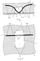
- the device in Fig. 1 corresponds to a first preferred embodiment in a sectional view seen from the side and comprises a recess 1 on the underside of the concrete ceiling 3, which is formed by a cup-shaped recess body 2.
- the recess 1 formed by the recess body has a width of 5 to 10 cm, preferably 6 to 8 cm, and a height of 4 to 10 cm, preferably 5 to 7 cm.
- the recess body 2 made of sheet metal or plastic may, for example, have a rectangular, trapezoidal or curved cross section.
- a cavity (recess 1) formed by the recess body 2 forms adjacent to the underside of the concrete ceiling 3. It is also conceivable that the recess body 2 consists of dimensionally stable foam or the like, which is scraped out after demoulding and thus produces the recess 1 ,
- the embodiment of Fig. 1 further comprises a rod 6, which extends through the wall of the recess body 2 on two sides, forming an attachment portion 6a and two anchoring portions 6b.
- the rod 6 is also attached to the recess body 2 before concreting the ceiling or is already firmly attached to the recess body 2 and is nailed together with this on the formwork 4.
- the appendage portion 6a comes to lie completely in the recess 1 and is bent down to facilitate attachment of shackles, hooks, ropes or the like. By placing the appendage section completely in the concrete deck, no parts of the elevator assembly anchor will protrude into the wellhead area of the elevator shaft. That leads to the whole Room of the elevator shaft can be used up to the ceiling for the elevator.
- the two ends of the rod 6 extend 25-50 cm into the concrete ceiling 3 and thereby form the two anchoring sections 6b.
- the rod 6 is pulled up at both ends in the region of the anchoring sections 6b in order to achieve a higher outbreak resistance in the concrete pavement.
- loads of several tons can be carried.
- Such a device according to the invention can be used flexibly and can easily be adapted to the respective thickness of the concrete floor.
- Fig. 2 shows a top view of in Fig. 1 said embodiment.
- the recess body with a width of 5 - 10 cm, preferably 6 - 8 cm, is elongated with a length of 12 - 25 cm, preferably 15 - 20 cm formed.
- the elongated shape allows easy attachment of shackles, hooks, ropes or the like, without significantly reducing the strength of the concrete surface over a large area. Due to the asymmetrical arrangement of the appendage section 6a in the recess 1, shackles, hooks, ropes or the like can be attached even more easily from one side.
- the above-described first embodiment has the advantage that attachment and anchoring portions 6a, 6b are formed by one and the same rod 6, which simplifies the manufacture of the elevator assembly anchor.
- the anchoring sections 6b can project as far as desired into the concrete floor 3. Thus, a very high breakout resistance can be achieved, which allows the carrying of loads of several tons. Since the anchorage is guided horizontally rather than vertically, as in conventional lift assembly anchors, into the ceiling, this embodiment can also be used in concrete slabs of lesser thickness and still carry loads of several tons.
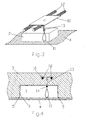
- the device in Fig. 3 2 corresponds to a second embodiment and comprises a metal plate 10 lying in the concrete above the recess.
- This metal plate 10 forms the anchoring section and can reach over the recess in order to ensure a better load distribution.
- the rod 12 extends, preferably on both sides, 25 - 50 cm above the Recess body 2 addition.
- the rod 12 is mounted transversely to the longitudinal direction of the recess body 2.
- the appendage section 11 may be in the form of an eyelet or loop and is attached to the metal plate via a rod 13.
- the appendage section 11 comes to lie asymmetrically in the recess.
- the recess can, as mentioned in the first preferred embodiment, be formed by a mounted on the formwork 4 recess body 2.
- Fig. 4 shows the in Fig. 3 said embodiment seen in a sectional view from the side.
- the appendage portion 11 is in the form of an eyelet or loop and may be attached to the rod 13 attached to the metal plate 10 via a clamping or threaded sleeve 14.
- the asymmetrical arrangement of attachment portion 11 and recess 1 facilitates attachment of shackles, hooks, ropes or the like.
- the metal plate 10 can be additionally anchored by at least one rod 12 for load distribution.
- the recess body 2 can be fastened with means for nailing 5 on the formwork 4 of the concrete ceiling 3 in order to prevent any displacement during the pouring of the concrete.
- Fig. 5 shows a top view of in FIG. 3 and FIG. 4 said embodiment.
- the metal plate 10 projects beyond the recess body 2 for load distribution on both sides.
- the appendage section 11 comes to lie in the recess 1 and is thus offset into the concrete ceiling 3.
- the elevator mounting anchor projects into the shaft head area and the entire shaft head area can be used for the elevator.
- the metal plate 10 and the rod 12 load capacities of several tons can be achieved.
- the dimensions of the device can be chosen so that it can be poured into concrete ceilings of low thickness.
- the device in Fig. 6 corresponds to a third embodiment in a sectional view seen from the side and comprises a wave armature 20, which is located in the concrete ceiling 3 above the recess 1 and thereby forms the anchoring portion.
- the shaft anchor 20 is through the wall of the recess body 2 through a clamping or screw sleeve 14 with the Attachment section 11 connected.
- the appendage section 11 may be in the form of an eyelet or loop and comes to lie completely in the recess 1. Thus, the appending portion 11 does not protrude into the head area of the elevator shaft. Further, the appendage portion 11 may be asymmetrically mounted to facilitate attachment of shackles, hooks, ropes, or the like.
- the recess body 2 can be fastened with means for nailing 5 on the formwork 4 of the concrete ceiling 3 in order to prevent any displacement.
Landscapes
- Engineering & Computer Science (AREA)
- Architecture (AREA)
- Civil Engineering (AREA)
- Structural Engineering (AREA)
- Mechanical Engineering (AREA)
- Physics & Mathematics (AREA)
- Electromagnetism (AREA)
- Forms Removed On Construction Sites Or Auxiliary Members Thereof (AREA)
- Conveying And Assembling Of Building Elements In Situ (AREA)
Abstract
Description
- Aufzugsmontageanker mit einem Anhängeabschnitt zum Anhängen von Schäkeln, Haken, Seilen oder dergleichen und mindestens einem Verankerungsabschnitt zum Eingiessen in eine Betondecke.
- In Aufzug-Maschinenräumen oder im Schachtkopfbereich von Aufzugsschächten müssen zum Anhängen von Montageplattformen zur Montage oder Wartung des Aufzuges in der Decke des Schachtes Lastanker angebracht werden, welche Lasten von mehreren Tonnen halten können. Für diese Anwendung sind lastgeprüfte Aufzugsmontageanker bekannt. Ein Beispiel für einen solchen Aufzugsmontageanker ist eine vormontierte Kombination aus einem Wellenanker (Verankerungsabschnitt) und einer Seilöse (Anhängeabschnitt). Der Wellenanker wird in die Decke des Aufzugsschachtes einbetoniert und das Anhängen von Schäkeln, Haken, Seilen oder dergleichen geschieht über die Seilöse im Schachtkopfbereich. Um Tragfähigkeiten von bis zu 4 Tonnen zu erreichen, muss ein solcher Wellenanker eine Länge von etwa 30 cm aufweisen. Die Seilöse ragt gemäss einem solchen Aufzugsmontageanker bis zu 25 cm in den Schachtkopfbereich hinein. Eine solche Konstruktion braucht eine Deckenstärke von mindestens 30 cm. Für geringere Deckenstärken, bei denen nicht beliebig viel Platz für die Verankerung vorhanden ist, sind auch kleinere Varianten bekannt. Solche kleinere Varianten sind aber nur für geringere Lasten geprüft und zugelassen.
- Gegenstand der Erfindung ist es, eine Vorrichtung der eingangs genannten Art anzugeben, bei der der Anhängeabschnitt nicht den für den Aufzug verwendbaren Platz beansprucht und die dennoch eine Tragfähigkeit für Lasten von mehreren Tonnen aufweist.
- Erfindungsgemäss wird dies bei einer solchen Vorrichtung dadurch erreicht, dass der Anhängeabschnitt in einem Aussparungskörper angeordnet ist, der ebenfalls zum Eingiessen in die Betondecke angrenzend an deren untere Schalung vorgesehen ist und der in der Betondecke nach dem Entschalen einen den Anhängeabschnitt umgebenden Hohlraum angrenzend an die Unterseite der Decke erzeugt.
- Die Erfindung hat demnach den Vorteil, dass der Aufzugsmontageanker nicht in den Schachtkopfbereich vorstösst und dabei den Platz beansprucht, welcher sonst für den Aufzug verwendet werden kann.
- Gemäss einer ersten bevorzugten Ausführungsform ist der erfindungsgemässe Aussparungskörper länglich ausgebildet und weist eine Länge von 12 - 25 cm, vorzugsweise 15 - 20 cm, eine Breite von 5 - 10 cm, vorzugsweise 6 - 8 cm, und eine Höhe von 4 - 10 cm, vorzugsweise 5 - 7 cm, auf. Eine längliche Form des Aussparungskörper erleichtert das Anhängen von Schäkeln, Haken, Seilen oder dergleichen. Der Aussparungskörper kann aus formstabilem Schaumstoff oder dergleichen bestehen, welcher nach der Montage durch zB. Auskratzten entfernt werden kann. Der Aussparungskörper kann auch schalenförmig mit einer Wandung aus Blech oder Kunststoff ausgebildet sein. Weiter kann der Aussparungskörper mit Mitteln zum Annageln auf der Schalung der Betondecke versehen sein.
- Gemäss einer ersten bevorzugten Ausführungsform wird der Anhängeabschnitt durch einen Stab gebildet, weicher an zwei Stellen durch die Wandung des erfindungsgemässen Aussparungskörpers in den umgebenden Beton hineinreicht und dabei zwei Verankerungsabschnitte bildet. Der Stab kann vorzugsweise im Bereich des Anhängeabschnitts nach unten gebogen sein, um ein Anhängen von Schäkeln, Haken, Seilen oder dergleichen zu erleichtern. Um einen höheren Ausbruchwiderstand des Aufzugsmontageankers im Beton zu erreichen, kann der Stab im Bereich wenigstens eines Verankerungsabschnittes hochgezogen sein. Eine solche bevorzugte Ausführungsform hat den Vorteil, dass Anhänge- und Verankerungsabschnitt aus einem Stab gebildet werden. Eine solche erfindungsgemässe Vorrichtung ist leicht herzustellen und kann fest mit dem Aussparungskörper verbunden werden, um eine Montage auf der Schalung zu erleichtern.
- Gemäss einer zweiten Ausführungsform umfasst der Verankerungsabschnitt eine über dem Aussparungskörper liegende Metallplatte, welche durch die Wandung des Aussparungskörpers hindurch mit dem Anhängeabschnitt verbunden ist. Der Anhängeabschnitt kann die Form einer Öse oder Schlaufe aufweisen und kommt in der oben beschriebenen Aussparung zu liegen. Zur Lastverteilung kann die Metallplatte auf mindestens einer Seite über den Bereich der Aussparung hinausreichen. Zur weiteren Lastverteilung kann mindestens ein Stab an der Metallplatte befestigt sein. Dieser Stab reicht, vorzugsweise auf beiden Seiten, 25 - 50 cm über die Metallplatte hinaus.
- Gemäss einer dritten Ausführungsform umfasst der Verankerungsabschnitt einen Wellenanker, der sich im Beton über dem Aussparungskörper befindet und welcher durch die Wandung des Aussparungskörpers hindurch mit dem Anhängeabschnitt verbunden ist. Der Anhängeabschnitt kann die Form einer Öse oder Schlaufe aufweisen und kommt in der oben beschriebenen Aussparung zu liegen.
- Vorzugsweise kann der Anhängeabschnitt in allen Ausführungsformen asymmetrisch zur Längsachse der Aussparung angebracht sein, um ein Anhängen von Schäkeln, Haken, Seilen oder dergleichen zu erleichtern.
- Die Erfindung soll nachfolgend anhand von Ausführungsbeispielen im Zusammenhang mit der Zeichnung näher erläutert werden. Es zeigen:
- Fig. 1
- eine erste Ausführungsform einer erfindungsgemässen Vorrichtung mit einem Stab als Anhänge- und Verankerungsabschnitt in einer Schnittdarstellung von der Seite gesehen;
- Fig. 2
- die Ausführungsform von
Fig. 1 in einer Aufsicht; - Fig. 3
- eine zweite Ausführungsform einer erfindungsgemässen Vorrichtung in perspektivischer Darstellung mit einer Metallplatte als Verankerunsabschnitt;
- Fig. 4
- eine Schnittdarstellung der Vorrichtung von
Fig. 3 von der Seite gesehen; - Fig. 5
- eine Aufsicht der Vorrichtung von
Fig. 3 ; - Fig. 6
- eine dritte Ausführungsform einer erfindungsgemässen Vorrichtung in einer Schnittdarstellung von der Seite gesehen.
- Die Vorrichtung in
Fig. 1 entspricht einer ersten bevorzugten Ausführungsform in einer Schnittdarstellung von der Seite gesehen und umfasst eine Aussparung 1 an der Unterseite der Betondecke 3, welche durch einen schalenförmigen Aussparungskörper 2 gebildet wird. Die durch den Aussparungskörper entstehende Aussparung 1 weist eine Breite von 5 - 10 cm, vorzugsweise 6 - 8 cm, und eine Höhe von 4 - 10 cm, vorzugsweise 5 - 7 cm, auf. Der aus Blech oder Kunstoff hergestellte Aussparungskörper 2 kann z.B. einen rechteckigen, trapezförmigen oder gewölbten Querschnitt aufweisen. Vor dem Betonieren der Decke wird der Aussparungskörper 2 mit Mittel zum Annageln 5 auf der Schalung 4 der Betondecke 3 befestigt, um allfälliges Verschieben beim Eingiessen des Betons zu verhindern. Beim Entschalen entsteht ein durch den Aussparungskörper 2 geformter Hohlraum (Aussparung 1) angrenzend an die Unterseite der Betondecke 3. Es ist auch denkbar, dass der Aussparungskörper 2 aus formstabilem Schaumstoff oder dergleichen besteht, welcher nach dem Entschalen ausgekratzt wird und so die Aussparung 1 erzeugt. - Die Ausführungsform von
Fig. 1 umfasst weiter einen Stab 6, welcher an zwei Seiten durch die Wandung des Aussparungskörpers 2 hindurch reicht und dabei einen Anhängeabschnitt 6a und zwei Verankerungsabschnitte 6b bildet. Der Stab 6 wird ebenfalls vor dem Betonieren der Decke am Aussparungskörper 2 befestigt oder ist bereits fest am Aussparungskörper 2 befestigt und wird zusammen mit diesem auf der Schalung 4 angenagelt. Der Anhängeabschnitt 6a kommt vollständig in der Aussparung 1 zu liegen und ist nach unten gebogen, um ein Anhängen von Schäkeln, Haken, Seilen oder dergleichen zu erleichtern. Indem der Anhängeabschnitt vollständig in die Betondecke hineinversetzt wird, ragen keine Teile des Aufzugsmontageankers in den Schachtkopfbereich des Aufzugsschachtes hinein. Das führt dazu, dass der gesamte Raum des Aufzugsschachtes bis zur Decke hin für den Aufzug verwendet werden kann. Die beiden Enden des Stabes 6 reichen 25 - 50 cm in die Betondecke 3 hinein und bilden dabei die beiden Verankerungsabschnitte 6b. Der Stab 6 ist an beiden Enden im Bereich der Verankerungsabschnitte 6b hochgezogen, um einen höheren Ausbruchwiderstand in der Betondecke zu erreichen. Je nach Länge und Dicke des Stabes können Lasten von mehreren Tonnen getragen werden. Eine solche erfindungsgemässe Vorrichtung ist flexibel einsetzbar und kann leicht der jeweiligen Stärke der Betondecke angepasst werden. -
Fig. 2 zeigt eine Aufsicht der inFig. 1 genannten Ausführungsform. Der Aussparungskörper mit einer Breite von 5 - 10 cm, vorzugsweise 6 - 8 cm, ist länglich mit einer Länge von 12 - 25 cm, vorzugsweise 15 - 20 cm, ausgebildet. Die längliche Form lässt ein leichtes Anhängen von Schäkeln, Haken, Seilen oder dergleichen zu, ohne die Stärke der Betondecke über eine grosse Fläche massgeblich zu verringern. Durch die asymmetrische Anordnung des Anhängeabschnitt 6a in der Aussparung 1, können Schäkel, Haken, Seile oder dergleichen noch leichter von einer Seite her angehängt werden. - Die vorbeschriebene erste Ausführungsform hat den Vorteil, dass Anhänge- und Verankerungsabschnitt 6a, 6b durch ein und denselben Stab 6 gebildet werden, was die Herstellung des Aufzugsmontageankers vereinfacht. Die Verankerungsabschnitte 6b können beliebig weit in die Betondecke 3 hineinragen. Somit kann ein sehr hoher Ausbruchwiderstand erreicht werden, was das Tragen von Lasten von mehreren Tonnen ermöglicht. Da die Verankerung waagrecht und nicht senkrecht, wie bei herkömmlichen Aufzugsmontageankem, in die Decke hineingeführt wird, kann diese Ausführungsform auch in Betondecken von geringerer Stärke verwendet werden und trotzdem Lasten von mehreren Tonnen tragen.
- Die Vorrichtung in
Fig. 3 entspricht einer zweiten Ausführungsform und umfasst eine im Beton über der Aussparung liegende Metallplatte 10. Diese Metallplatte 10 bildet den Verankerungsabschnitt und kann über die Aussparung hinweg reichen, um eine besseren Lastverteilung zu gewährleisten. Durch das Anbringen von mindestens einem Stab 12 an der Metallplatte 10, kann eine noch besseren Lastverteilung erreicht werden. Der Stab 12 reicht, vorzugsweise auf beiden Seiten, 25 - 50 cm über den Aussparungskörper 2 hinaus. Bevorzugt wird der Stab 12 quer zur Längsrichtung des Aussparungskörpers 2 angebracht. Der Anhängeabschnitt 11 kann die Form einer Öse oder Schlaufe aufweisen und wird über einen Stab 13 an der Metallplatte befestigt. Der Anhängeabschnitt 11 kommt dabei asymmetrisch in der Aussparung zu liegen. Die Aussparung kann, wie in der ersten bevorzugten Ausführungsform genannt, durch einen auf der Schalung 4 angebrachten Aussparungskörper 2 gebildet werden. -
Fig. 4 zeigt die inFig. 3 genannte Ausführungsform in einer Schnittdarstellung von der Seite gesehen. Der Anhängeabschnitt 11 weist die Form einer Öse oder Schlaufe auf und kann über eine Klemm- oder Schraubhülse 14 an dem an der Metallplatte 10 befestigten Stab 13 befestigt werden. Die asymmetrische Anordnung von Anhängeabschnitt 11 und Aussparung 1 erleichtert ein Anhängen von Schäkeln, Haken, Seilen oder dergleichen. Die Metallplatte 10 kann zur Lastverteilung zusätzlich durch mindestens einen Stab 12 verankert werden. Der Aussparungskörper 2 kann mit Mittel zum Annageln 5 auf der Schalung 4 der Betondecke 3 befestigt werden, um allfälliges Verschieben beim Eingiessen des Betons zu verhindern. -
Fig. 5 zeigt eine Aufsicht der inFig. 3 und Fig. 4 genannten Ausführungsform. Die Metallplatte 10 ragt zur Lastverteilung auf beiden Seiten über den Aussparungskörper 2 hinaus. - Auch in der zweiten Ausführungsform kommt der Anhängeabschnitt 11 in der Aussparung 1 zu liegen und ist somit in die Betondecke 3 hineinversetzt. Dadurch ragt kein Teil des Aufzugsmontageankers in den Schachtkopfbereich und der gesamte Schachtkopfbereich kann für den Aufzug verwendet werden. Durch die Metallplatte 10 und den Stab 12 können Tragfähigkeiten von mehreren Tonnen erreicht werden. Weiter können die Dimensionen der Vorrichtung so gewählt werden, dass sie auch in Betondecken von geringer Stärke eingegossen werden kann.
- Die Vorrichtung in
Fig. 6 entspricht einer dritten Ausführungsform in einer Schnittdarstellung von der Seite gesehen und umfasst einen Wellenanker 20, der sich in der Betondecke 3 über der Aussparung 1 befindet und dabei den Verankerungsabschnitt bildet. Der Wellenanker 20 ist durch die Wandung des Aussparungskörpers 2 hindurch über eine Klemm- oder Schraubhülse 14 mit dem Anhängeabschnitt 11 verbunden. Der Anhängeabschnitt 11 kann die Form einer Öse oder Schlaufe aufweisen und kommt vollständig in der Aussparung 1 zu liegen. Somit ragt der Anhängeabschnitt 11 nicht In den Kopfbereich des Aufzugsschachtes hinein. Weiter kann der Anhängeabschnitt 11 asymmetrisch angebracht werden, um ein Anhängen von Schäkeln, Haken, Seilen oder dergleichen zu erleichtern. Der Aussparungskörper 2 kann mit Mittel zum Annageln 5 auf der Schalung 4 der Betondecke 3 befestigt werden, um allfälliges Verschieben zu verhindern. -
- 1
- Aussparung
- 2
- Aussparungskörper
- 3
- Betondecke
- 4
- Schalung
- 5
- Mittel zum Annageln
- 6
- Stab
- 6a
- Anhängeabschnitt
- 6b
- Verankerungsabschnitt
- 10
- Metallplatte
- 11
- Verankerungsabschnitt
- 12
- Stab
- 13
- Stab
- 14
- Klemm- oder Schraubhülse
- 20
- Wellenanker
Claims (15)
- Aufzugsmontageanker mit einem Anhängeabschnitt (6a;11) zum Anhängen von Schäkeln, Haken, Seilen oder dergleichen und mindestens einem Verankerungsabschnitt zum Eingiessen in eine Betondecke (3), dadurch gekennzeichnet, dass der Anhängeabschnitt (6a; 11) in einem Aussparungskörper (2) angeordnet ist, der ebenfalls zum Eingiessen in die Betondecke (3) angrenzend an deren untere Schalung (4) vorgesehen ist und der in der Betondecke (3) nach dem Entschalen einen den Anhängeabschnitt (6a;11) umgebenden Hohlraum (1) angrenzend an die Unterseite der Decke erzeugt.
- Vorrichtung nach Anspruch 1, dadurch gekennzeichnet, dass der Aussparungskörper (2) länglich ausgebildet ist.
- Vorrichtung nach Anspruch 1 oder 2, dadurch gekennzeichnet, dass der Aussparungskörper (2) eine Länge von 12 - 25 cm, vorzugsweise 15 - 20 cm, eine Breite von 5 - 10 cm, vorzugsweise 6 - 8 cm, und eine Höhe von 4 - 10 cm, vorzugsweise 5 - 7 cm, aufweist.
- Vorrichtung nach einem der Ansprüche 1 - 3, dadurch gekennzeichnet, dass der Aussparungskörper (2) aus einem formstabilen Schaumstoff oder dergleichen besteht, welches nach der Montage durch z.B. Auskratzten entfernt werden kann.
- Vorrichtung nach einem der Ansprüche 1 - 3, dadurch gekennzeichnet, dass der Aussparungskörper (2) schalenförmig ist und eine Wandung aus Blech oder Kunststoff aufweist.
- Vorrichtung nach einem der Ansprüche 1 - 5, dadurch gekennzeichnet, dass der Aussparungskörper (2) mit Mitteln zum Annageln (5) auf der Schalung (4) der Betondecke (3) versehen ist.
- Vorrichtung nach Anspruch 1, dadurch gekennzeichnet, dass der Anhängeabschnitt (6a) durch einen Stab (6) gebildet wird, welcher an zwei Stellen durch die Wandung des Aussparungskörpers (2) in den umgebenden Beton (3) hineinreicht und dort zwei Verankerungsabschnitte (6b) bildet.
- Vorrichtung nach Anspruch 7, dadurch gekennzeichnet, dass der Stab (6) im Bereich des Anhängeabschnitts (6a) nach unten gebogen ist, um ein Anschlagen von Schäkeln, Haken, Seilen oder dergleichen zu erleichtern.
- Vorrichtung nach einem der Ansprüche 7 oder 8, dadurch gekennzeichnet, dass der Stab (6) im Bereich wenigstens eines Verankerungsabschnittes (6b) hochgezogen ist, um einen höheren Ausbruchwiderstand im Beton (3) zu erreichen.
- Vorrichtung nach Anspruch 1, dadurch gekennzeichnet, dass der Verankerungsabschnitt eine über dem Aussparungskörper (2) liegende Metallplatte (10) umfasst, welche durch die Wandung des Aussparungskörpers (2) hindurch mit dem Anhängeabschnitt (11) verbunden ist.
- Vorrichtung nach Anspruch 10, dadurch gekennzeichnet, dass die Metallplatte (10) zur Lastverteilung auf mindestens einer Seite über den Bereich der Aussparung (1) hinausreicht.
- Vorrichtung nach einem der Ansprüche 10 oder 11, dadurch gekennzeichnet, dass mindestens ein Stab (12) zur Lastverteilung an der Metallplatte (10) befestigt ist und das der Stab (12), vorzugsweise auf beiden Seiten, 25 - 50 cm über die Metallplatte (10) hinausreicht.
- Vorrichtung nach Anspruch 1, dadurch gekennzeichnet, dass der Verankerungsabschnitt einen Wellenanker (20) umfasst, der sich im Beton (3) über dem Aussparungskörper (2) befindet und welcher durch die Wandung des Aussparungskörpers (2) hindurch mit dem Anhängeabschnitt (11) verbunden ist.
- Vorrichtung nach einem der Ansprüche 10 - 13 dadurch gekennzeichnet, dass der Anhängeabschnitt (11) die Form einer Öse oder Schlaufe aufweist.
- Vorrichtung nach einem der Ansprüche 1, 2, 3, 7, 10, 13 oder 14 dadurch gekennzeichnet, dass der Anhängeabschnitt (6a;11) asymmetrisch zur Längsachse der Aussparung (1) angebracht ist, um ein Anhängen von einer Seite her zu erleichtern.
Applications Claiming Priority (1)
| Application Number | Priority Date | Filing Date | Title |
|---|---|---|---|
| CH00591/08A CH718496B1 (de) | 2008-04-16 | 2008-04-16 | Aufzugsmontageanker. |
Publications (3)
| Publication Number | Publication Date |
|---|---|
| EP2110486A2 true EP2110486A2 (de) | 2009-10-21 |
| EP2110486A3 EP2110486A3 (de) | 2012-10-03 |
| EP2110486B1 EP2110486B1 (de) | 2020-03-25 |
Family
ID=40790837
Family Applications (1)
| Application Number | Title | Priority Date | Filing Date |
|---|---|---|---|
| EP09005209.3A Active EP2110486B1 (de) | 2008-04-16 | 2009-04-09 | Aufzugsmontageanker |
Country Status (2)
| Country | Link |
|---|---|
| EP (1) | EP2110486B1 (de) |
| CH (1) | CH718496B1 (de) |
Cited By (5)
| Publication number | Priority date | Publication date | Assignee | Title |
|---|---|---|---|---|
| DE202010010127U1 (de) | 2010-07-12 | 2011-10-24 | Pfeifer Seil- Und Hebetechnik Gmbh | Verwahrungsbox und Verwendung einer Verwahrungsbox |
| WO2013064497A1 (de) | 2011-10-31 | 2013-05-10 | Inventio Ag | Lastschlaufenbox und ankerungsvorrichtung |
| EP2913458A1 (de) * | 2014-02-28 | 2015-09-02 | Lesage Developpement S.A.S. | Mauer mit integrierter schalung, die eine gesicherte öffnung umfasst, verschalungsvorrichtung einer solchen öffnung und herstellungsverfahren einer solchen mauer mit integrierter schalung |
| CN106049883A (zh) * | 2016-05-23 | 2016-10-26 | 中交第航务工程局有限公司 | 混凝土构件新型吊点施工工艺 |
| DE102016118883A1 (de) * | 2016-10-05 | 2018-04-05 | Georg Weidner | Schweißbare Betonschlaufe |
Families Citing this family (1)
| Publication number | Priority date | Publication date | Assignee | Title |
|---|---|---|---|---|
| CN104328804B (zh) * | 2014-11-10 | 2016-03-23 | 苏州多固工程设计有限公司 | 支撑式混凝土变形缝止水型腔模 |
Family Cites Families (4)
| Publication number | Priority date | Publication date | Assignee | Title |
|---|---|---|---|---|
| FR2167274A5 (en) * | 1972-01-11 | 1973-08-24 | Arteon Marcel | Cast panels contg inserts -eg anchorage bolts temporarily - located during casting between split plastic (gps) shells |
| DE3248604A1 (de) * | 1982-12-30 | 1984-07-12 | Gebr. Seifert GmbH & Co, 5880 Lüdenscheid | Vorrichtung zum aufhaengen von betonbauteilen od. dgl. an die lasthaken von kraenen od. dgl. |
| DE3633633A1 (de) * | 1986-10-03 | 1988-06-16 | Modersohn Gmbh & Co Kg Wilh | Anschlagpunkt fuer die befestigung einer absturzsicherung |
| DE29722108U1 (de) * | 1997-12-16 | 1999-04-15 | Pfeifer Seil- und Hebetechnik GmbH & Co, 87700 Memmingen | Betonfertigteil und Transportanker für den Transport dieses Betonfertigteiles |
-
2008
- 2008-04-16 CH CH00591/08A patent/CH718496B1/de unknown
-
2009
- 2009-04-09 EP EP09005209.3A patent/EP2110486B1/de active Active
Cited By (8)
| Publication number | Priority date | Publication date | Assignee | Title |
|---|---|---|---|---|
| DE202010010127U1 (de) | 2010-07-12 | 2011-10-24 | Pfeifer Seil- Und Hebetechnik Gmbh | Verwahrungsbox und Verwendung einer Verwahrungsbox |
| EP2407612A2 (de) | 2010-07-12 | 2012-01-18 | Pfeifer Seil- und Hebetechnik GmbH | Verwahrungsbox und Verwendung einer Verwahrungsbox |
| EP2407612A3 (de) * | 2010-07-12 | 2013-12-11 | Pfeifer Holding GmbH & Co. KG | Verwahrungsbox und Verwendung einer Verwahrungsbox |
| WO2013064497A1 (de) | 2011-10-31 | 2013-05-10 | Inventio Ag | Lastschlaufenbox und ankerungsvorrichtung |
| EP2913458A1 (de) * | 2014-02-28 | 2015-09-02 | Lesage Developpement S.A.S. | Mauer mit integrierter schalung, die eine gesicherte öffnung umfasst, verschalungsvorrichtung einer solchen öffnung und herstellungsverfahren einer solchen mauer mit integrierter schalung |
| FR3018087A1 (fr) * | 2014-02-28 | 2015-09-04 | Lesage Dev | Mur comportant une ouverture securisee, dispositif de coffrage d'une telle ouverture et procede de fabrication d'un tel mur |
| CN106049883A (zh) * | 2016-05-23 | 2016-10-26 | 中交第航务工程局有限公司 | 混凝土构件新型吊点施工工艺 |
| DE102016118883A1 (de) * | 2016-10-05 | 2018-04-05 | Georg Weidner | Schweißbare Betonschlaufe |
Also Published As
| Publication number | Publication date |
|---|---|
| EP2110486A3 (de) | 2012-10-03 |
| EP2110486B1 (de) | 2020-03-25 |
| CH718496B1 (de) | 2022-10-14 |
Similar Documents
| Publication | Publication Date | Title |
|---|---|---|
| EP0418699B1 (de) | Dichtungseinrichtung für Betonfugen sowie Verfahren zu ihrer Verfüllung | |
| AT519067B1 (de) | Dehnfugenschalung | |
| AT513576B1 (de) | Wandschalungssystem sowie ein Verfahren zum Herstellen eines Wandschnitts mit einer Isolierschalung | |
| EP2110486A2 (de) | Aufzugsmontageanker | |
| DE2900759A1 (de) | Doppelbodensystem und verfahren zur herstellung | |
| CH678204A5 (de) | ||
| DE102020109531B3 (de) | Schalungssystem | |
| DE7714716U1 (de) | Anker fuer das abfangen von abstand zur tragenden wandung belassenden bauelementen | |
| EP2516761B1 (de) | Vorrichtung zum verbinden von zwei durch eine fuge getrennte bauteile und zur aufnahme von zwischen den bauteilen auftretenden querkräften | |
| EP3892789B1 (de) | Schalungssystem | |
| EP1387910A1 (de) | Verbindungselement und verfahren zum verbinden eines betonfertigteils mit einem gebäudeabschnitt | |
| DE9409626U1 (de) | Balkonkonstruktion | |
| EP3839162B1 (de) | Thermisch isolierendes bauelement zum einsatz in einer trennfuge zwischen zwei bauwerksteilen | |
| AT508798A2 (de) | Schalung | |
| DE102016118014A1 (de) | Binder, insbesondere Dachbinder für eine Halle | |
| CH696204A5 (de) | Vorrichtung zur Schubbewehrung. | |
| EP3754134A1 (de) | Spannvorrichtung für eine eckverschalung | |
| DE2923153C2 (de) | Haltevorrichtung für Stützwangen zum Abstützen von Hanggut an einer Böschung | |
| DE102012007700B4 (de) | Stahlbetondecke mit mindestens einer darauf befestigten Fußpfette | |
| DE202017001504U1 (de) | Leichtbauwand, insbesondere zur Erstellung einer Trennwand in Räumen von Bauwerken | |
| CH715831A2 (de) | Verbindungselement zur Verbindung einer Abschalungsplatte mit einer weiteren Baueinheit, Abschalungseinheit mit Verbindungselement, Verbindungseinheit mit Verbindungselement, Teileset zum Aufbau einer Abschalung und Abschalung zur Bildung eines Giessbetonelements. | |
| WO2000005461A1 (de) | Stahlbetonplatte und schubbewehrungselement zur schubbewehrung von stahlbetonplatten | |
| EP3854953B1 (de) | Befestigungsanordnung | |
| EP1079037A2 (de) | Verfahren zur Erstellung einer Deckenrand-Abschalung sowie eine Deckenrand-Abschalung | |
| DE29505448U1 (de) | Randschalungselement |
Legal Events
| Date | Code | Title | Description |
|---|---|---|---|
| PUAI | Public reference made under article 153(3) epc to a published international application that has entered the european phase |
Free format text: ORIGINAL CODE: 0009012 |
|
| AK | Designated contracting states |
Kind code of ref document: A2 Designated state(s): AT BE BG CH CY CZ DE DK EE ES FI FR GB GR HR HU IE IS IT LI LT LU LV MC MK MT NL NO PL PT RO SE SI SK TR |
|
| PUAL | Search report despatched |
Free format text: ORIGINAL CODE: 0009013 |
|
| AK | Designated contracting states |
Kind code of ref document: A3 Designated state(s): AT BE BG CH CY CZ DE DK EE ES FI FR GB GR HR HU IE IS IT LI LT LU LV MC MK MT NL NO PL PT RO SE SI SK TR |
|
| AX | Request for extension of the european patent |
Extension state: AL BA RS |
|
| RIC1 | Information provided on ipc code assigned before grant |
Ipc: E04G 21/14 20060101ALI20120829BHEP Ipc: B66C 1/66 20060101ALI20120829BHEP Ipc: E04B 1/41 20060101AFI20120829BHEP |
|
| 17P | Request for examination filed |
Effective date: 20130321 |
|
| STAA | Information on the status of an ep patent application or granted ep patent |
Free format text: STATUS: EXAMINATION IS IN PROGRESS |
|
| 17Q | First examination report despatched |
Effective date: 20170120 |
|
| GRAP | Despatch of communication of intention to grant a patent |
Free format text: ORIGINAL CODE: EPIDOSNIGR1 |
|
| STAA | Information on the status of an ep patent application or granted ep patent |
Free format text: STATUS: GRANT OF PATENT IS INTENDED |
|
| INTG | Intention to grant announced |
Effective date: 20190819 |
|
| GRAS | Grant fee paid |
Free format text: ORIGINAL CODE: EPIDOSNIGR3 |
|
| GRAJ | Information related to disapproval of communication of intention to grant by the applicant or resumption of examination proceedings by the epo deleted |
Free format text: ORIGINAL CODE: EPIDOSDIGR1 |
|
| GRAL | Information related to payment of fee for publishing/printing deleted |
Free format text: ORIGINAL CODE: EPIDOSDIGR3 |
|
| STAA | Information on the status of an ep patent application or granted ep patent |
Free format text: STATUS: EXAMINATION IS IN PROGRESS |
|
| INTC | Intention to grant announced (deleted) | ||
| GRAP | Despatch of communication of intention to grant a patent |
Free format text: ORIGINAL CODE: EPIDOSNIGR1 |
|
| STAA | Information on the status of an ep patent application or granted ep patent |
Free format text: STATUS: GRANT OF PATENT IS INTENDED |
|
| GRAA | (expected) grant |
Free format text: ORIGINAL CODE: 0009210 |
|
| STAA | Information on the status of an ep patent application or granted ep patent |
Free format text: STATUS: THE PATENT HAS BEEN GRANTED |
|
| INTG | Intention to grant announced |
Effective date: 20200129 |
|
| AK | Designated contracting states |
Kind code of ref document: B1 Designated state(s): AT BE BG CH CY CZ DE DK EE ES FI FR GB GR HR HU IE IS IT LI LT LU LV MC MK MT NL NO PL PT RO SE SI SK TR |
|
| REG | Reference to a national code |
Ref country code: GB Ref legal event code: FG4D Free format text: NOT ENGLISH |
|
| REG | Reference to a national code |
Ref country code: AT Ref legal event code: REF Ref document number: 1248715 Country of ref document: AT Kind code of ref document: T Effective date: 20200415 Ref country code: IE Ref legal event code: FG4D Free format text: LANGUAGE OF EP DOCUMENT: GERMAN |
|
| REG | Reference to a national code |
Ref country code: DE Ref legal event code: R096 Ref document number: 502009016140 Country of ref document: DE |
|
| REG | Reference to a national code |
Ref country code: CH Ref legal event code: NV Representative=s name: RENTSCH PARTNER AG, CH Ref country code: CH Ref legal event code: PFA Owner name: JORDAHL H-BAU AG, CH Free format text: FORMER OWNER: ANKABA ANKERTECHNIK UND BAUHANDEL AG, CH |
|
| REG | Reference to a national code |
Ref country code: DE Ref legal event code: R082 Ref document number: 502009016140 Country of ref document: DE Representative=s name: ZEUNER SUMMERER STUETZ PATENT- UND RECHTSANWAL, DE Ref country code: DE Ref legal event code: R081 Ref document number: 502009016140 Country of ref document: DE Owner name: JORDAHL H-BAU AG, CH Free format text: FORMER OWNER: ANKABA ANKERTECHNIK UND BAUHANDEL AG, BRUETTISELLEN, CH |
|
| REG | Reference to a national code |
Ref country code: LU Ref legal event code: HC Owner name: JORDAHL H-BAU AG; CH Free format text: FORMER OWNER: ANKABA ANKERTECHNIK UND BAUHANDEL AG Effective date: 20200624 |
|
| PG25 | Lapsed in a contracting state [announced via postgrant information from national office to epo] |
Ref country code: NO Free format text: LAPSE BECAUSE OF FAILURE TO SUBMIT A TRANSLATION OF THE DESCRIPTION OR TO PAY THE FEE WITHIN THE PRESCRIBED TIME-LIMIT Effective date: 20200625 Ref country code: FI Free format text: LAPSE BECAUSE OF FAILURE TO SUBMIT A TRANSLATION OF THE DESCRIPTION OR TO PAY THE FEE WITHIN THE PRESCRIBED TIME-LIMIT Effective date: 20200325 |
|
| PG25 | Lapsed in a contracting state [announced via postgrant information from national office to epo] |
Ref country code: BG Free format text: LAPSE BECAUSE OF FAILURE TO SUBMIT A TRANSLATION OF THE DESCRIPTION OR TO PAY THE FEE WITHIN THE PRESCRIBED TIME-LIMIT Effective date: 20200625 Ref country code: GR Free format text: LAPSE BECAUSE OF FAILURE TO SUBMIT A TRANSLATION OF THE DESCRIPTION OR TO PAY THE FEE WITHIN THE PRESCRIBED TIME-LIMIT Effective date: 20200626 Ref country code: LV Free format text: LAPSE BECAUSE OF FAILURE TO SUBMIT A TRANSLATION OF THE DESCRIPTION OR TO PAY THE FEE WITHIN THE PRESCRIBED TIME-LIMIT Effective date: 20200325 Ref country code: HR Free format text: LAPSE BECAUSE OF FAILURE TO SUBMIT A TRANSLATION OF THE DESCRIPTION OR TO PAY THE FEE WITHIN THE PRESCRIBED TIME-LIMIT Effective date: 20200325 Ref country code: SE Free format text: LAPSE BECAUSE OF FAILURE TO SUBMIT A TRANSLATION OF THE DESCRIPTION OR TO PAY THE FEE WITHIN THE PRESCRIBED TIME-LIMIT Effective date: 20200325 |
|
| REG | Reference to a national code |
Ref country code: NL Ref legal event code: MP Effective date: 20200325 |
|
| REG | Reference to a national code |
Ref country code: LT Ref legal event code: MG4D |
|
| PG25 | Lapsed in a contracting state [announced via postgrant information from national office to epo] |
Ref country code: NL Free format text: LAPSE BECAUSE OF FAILURE TO SUBMIT A TRANSLATION OF THE DESCRIPTION OR TO PAY THE FEE WITHIN THE PRESCRIBED TIME-LIMIT Effective date: 20200325 |
|
| REG | Reference to a national code |
Ref country code: AT Ref legal event code: HC Ref document number: 1248715 Country of ref document: AT Kind code of ref document: T Owner name: JORDAHL H-BAU AG, CH Effective date: 20200901 |
|
| PG25 | Lapsed in a contracting state [announced via postgrant information from national office to epo] |
Ref country code: LT Free format text: LAPSE BECAUSE OF FAILURE TO SUBMIT A TRANSLATION OF THE DESCRIPTION OR TO PAY THE FEE WITHIN THE PRESCRIBED TIME-LIMIT Effective date: 20200325 Ref country code: PT Free format text: LAPSE BECAUSE OF FAILURE TO SUBMIT A TRANSLATION OF THE DESCRIPTION OR TO PAY THE FEE WITHIN THE PRESCRIBED TIME-LIMIT Effective date: 20200818 Ref country code: RO Free format text: LAPSE BECAUSE OF FAILURE TO SUBMIT A TRANSLATION OF THE DESCRIPTION OR TO PAY THE FEE WITHIN THE PRESCRIBED TIME-LIMIT Effective date: 20200325 Ref country code: IS Free format text: LAPSE BECAUSE OF FAILURE TO SUBMIT A TRANSLATION OF THE DESCRIPTION OR TO PAY THE FEE WITHIN THE PRESCRIBED TIME-LIMIT Effective date: 20200725 Ref country code: CZ Free format text: LAPSE BECAUSE OF FAILURE TO SUBMIT A TRANSLATION OF THE DESCRIPTION OR TO PAY THE FEE WITHIN THE PRESCRIBED TIME-LIMIT Effective date: 20200325 Ref country code: SK Free format text: LAPSE BECAUSE OF FAILURE TO SUBMIT A TRANSLATION OF THE DESCRIPTION OR TO PAY THE FEE WITHIN THE PRESCRIBED TIME-LIMIT Effective date: 20200325 Ref country code: EE Free format text: LAPSE BECAUSE OF FAILURE TO SUBMIT A TRANSLATION OF THE DESCRIPTION OR TO PAY THE FEE WITHIN THE PRESCRIBED TIME-LIMIT Effective date: 20200325 |
|
| PG25 | Lapsed in a contracting state [announced via postgrant information from national office to epo] |
Ref country code: MC Free format text: LAPSE BECAUSE OF FAILURE TO SUBMIT A TRANSLATION OF THE DESCRIPTION OR TO PAY THE FEE WITHIN THE PRESCRIBED TIME-LIMIT Effective date: 20200325 |
|
| REG | Reference to a national code |
Ref country code: DE Ref legal event code: R097 Ref document number: 502009016140 Country of ref document: DE |
|
| PG25 | Lapsed in a contracting state [announced via postgrant information from national office to epo] |
Ref country code: IT Free format text: LAPSE BECAUSE OF FAILURE TO SUBMIT A TRANSLATION OF THE DESCRIPTION OR TO PAY THE FEE WITHIN THE PRESCRIBED TIME-LIMIT Effective date: 20200325 Ref country code: ES Free format text: LAPSE BECAUSE OF FAILURE TO SUBMIT A TRANSLATION OF THE DESCRIPTION OR TO PAY THE FEE WITHIN THE PRESCRIBED TIME-LIMIT Effective date: 20200325 Ref country code: DK Free format text: LAPSE BECAUSE OF FAILURE TO SUBMIT A TRANSLATION OF THE DESCRIPTION OR TO PAY THE FEE WITHIN THE PRESCRIBED TIME-LIMIT Effective date: 20200325 |
|
| REG | Reference to a national code |
Ref country code: BE Ref legal event code: MM Effective date: 20200430 |
|
| PLBE | No opposition filed within time limit |
Free format text: ORIGINAL CODE: 0009261 |
|
| STAA | Information on the status of an ep patent application or granted ep patent |
Free format text: STATUS: NO OPPOSITION FILED WITHIN TIME LIMIT |
|
| PG25 | Lapsed in a contracting state [announced via postgrant information from national office to epo] |
Ref country code: PL Free format text: LAPSE BECAUSE OF FAILURE TO SUBMIT A TRANSLATION OF THE DESCRIPTION OR TO PAY THE FEE WITHIN THE PRESCRIBED TIME-LIMIT Effective date: 20200325 Ref country code: BE Free format text: LAPSE BECAUSE OF NON-PAYMENT OF DUE FEES Effective date: 20200430 |
|
| 26N | No opposition filed |
Effective date: 20210112 |
|
| PG25 | Lapsed in a contracting state [announced via postgrant information from national office to epo] |
Ref country code: SI Free format text: LAPSE BECAUSE OF FAILURE TO SUBMIT A TRANSLATION OF THE DESCRIPTION OR TO PAY THE FEE WITHIN THE PRESCRIBED TIME-LIMIT Effective date: 20200325 |
|
| PG25 | Lapsed in a contracting state [announced via postgrant information from national office to epo] |
Ref country code: TR Free format text: LAPSE BECAUSE OF FAILURE TO SUBMIT A TRANSLATION OF THE DESCRIPTION OR TO PAY THE FEE WITHIN THE PRESCRIBED TIME-LIMIT Effective date: 20200325 Ref country code: MT Free format text: LAPSE BECAUSE OF FAILURE TO SUBMIT A TRANSLATION OF THE DESCRIPTION OR TO PAY THE FEE WITHIN THE PRESCRIBED TIME-LIMIT Effective date: 20200325 Ref country code: CY Free format text: LAPSE BECAUSE OF FAILURE TO SUBMIT A TRANSLATION OF THE DESCRIPTION OR TO PAY THE FEE WITHIN THE PRESCRIBED TIME-LIMIT Effective date: 20200325 |
|
| PG25 | Lapsed in a contracting state [announced via postgrant information from national office to epo] |
Ref country code: MK Free format text: LAPSE BECAUSE OF FAILURE TO SUBMIT A TRANSLATION OF THE DESCRIPTION OR TO PAY THE FEE WITHIN THE PRESCRIBED TIME-LIMIT Effective date: 20200325 |
|
| P01 | Opt-out of the competence of the unified patent court (upc) registered |
Effective date: 20230512 |
|
| PGFP | Annual fee paid to national office [announced via postgrant information from national office to epo] |
Ref country code: IE Payment date: 20240927 Year of fee payment: 16 Ref country code: DE Payment date: 20240918 Year of fee payment: 16 |
|
| PGFP | Annual fee paid to national office [announced via postgrant information from national office to epo] |
Ref country code: GB Payment date: 20240919 Year of fee payment: 16 |
|
| PGFP | Annual fee paid to national office [announced via postgrant information from national office to epo] |
Ref country code: LU Payment date: 20240918 Year of fee payment: 16 |
|
| PGFP | Annual fee paid to national office [announced via postgrant information from national office to epo] |
Ref country code: FR Payment date: 20240924 Year of fee payment: 16 |
|
| PGFP | Annual fee paid to national office [announced via postgrant information from national office to epo] |
Ref country code: CH Payment date: 20240919 Year of fee payment: 16 |
|
| PGFP | Annual fee paid to national office [announced via postgrant information from national office to epo] |
Ref country code: AT Payment date: 20240919 Year of fee payment: 16 |
|
| REG | Reference to a national code |
Ref country code: DE Ref legal event code: R119 Ref document number: 502009016140 Country of ref document: DE |
|
| REG | Reference to a national code |
Ref country code: CH Ref legal event code: H13 Free format text: ST27 STATUS EVENT CODE: U-0-0-H10-H13 (AS PROVIDED BY THE NATIONAL OFFICE) Effective date: 20251125 |
|
| PG25 | Lapsed in a contracting state [announced via postgrant information from national office to epo] |
Ref country code: LU Free format text: LAPSE BECAUSE OF NON-PAYMENT OF DUE FEES Effective date: 20250409 |
|
| REG | Reference to a national code |
Ref country code: AT Ref legal event code: MM01 Ref document number: 1248715 Country of ref document: AT Kind code of ref document: T Effective date: 20250409 |
|
| GBPC | Gb: european patent ceased through non-payment of renewal fee |
Effective date: 20250409 |
|
| PG25 | Lapsed in a contracting state [announced via postgrant information from national office to epo] |
Ref country code: DE Free format text: LAPSE BECAUSE OF NON-PAYMENT OF DUE FEES Effective date: 20251104 |
|
| PG25 | Lapsed in a contracting state [announced via postgrant information from national office to epo] |
Ref country code: GB Free format text: LAPSE BECAUSE OF NON-PAYMENT OF DUE FEES Effective date: 20250409 |
|
| PG25 | Lapsed in a contracting state [announced via postgrant information from national office to epo] |
Ref country code: AT Free format text: LAPSE BECAUSE OF NON-PAYMENT OF DUE FEES Effective date: 20250409 |
|
| PG25 | Lapsed in a contracting state [announced via postgrant information from national office to epo] |
Ref country code: FR Free format text: LAPSE BECAUSE OF NON-PAYMENT OF DUE FEES Effective date: 20250430 |
|
| PG25 | Lapsed in a contracting state [announced via postgrant information from national office to epo] |
Ref country code: CH Free format text: LAPSE BECAUSE OF NON-PAYMENT OF DUE FEES Effective date: 20250430 |
|
| PG25 | Lapsed in a contracting state [announced via postgrant information from national office to epo] |
Ref country code: IE Free format text: LAPSE BECAUSE OF NON-PAYMENT OF DUE FEES Effective date: 20250409 |