EP2110488B1 - Deckenanordnung - Google Patents
Deckenanordnung Download PDFInfo
- Publication number
- EP2110488B1 EP2110488B1 EP09251063.5A EP09251063A EP2110488B1 EP 2110488 B1 EP2110488 B1 EP 2110488B1 EP 09251063 A EP09251063 A EP 09251063A EP 2110488 B1 EP2110488 B1 EP 2110488B1
- Authority
- EP
- European Patent Office
- Prior art keywords
- panel carrier
- suspension device
- panel
- ceiling
- rigidifying means
- Prior art date
- Legal status (The legal status is an assumption and is not a legal conclusion. Google has not performed a legal analysis and makes no representation as to the accuracy of the status listed.)
- Active
Links
Images





Classifications
-
- E—FIXED CONSTRUCTIONS
- E04—BUILDING
- E04B—GENERAL BUILDING CONSTRUCTIONS; WALLS, e.g. PARTITIONS; ROOFS; FLOORS; CEILINGS; INSULATION OR OTHER PROTECTION OF BUILDINGS
- E04B9/00—Ceilings; Construction of ceilings, e.g. false ceilings; Ceiling construction with regard to insulation
- E04B9/18—Means for suspending the supporting construction
- E04B9/20—Means for suspending the supporting construction adjustable
-
- E—FIXED CONSTRUCTIONS
- E04—BUILDING
- E04B—GENERAL BUILDING CONSTRUCTIONS; WALLS, e.g. PARTITIONS; ROOFS; FLOORS; CEILINGS; INSULATION OR OTHER PROTECTION OF BUILDINGS
- E04B9/00—Ceilings; Construction of ceilings, e.g. false ceilings; Ceiling construction with regard to insulation
- E04B9/06—Ceilings; Construction of ceilings, e.g. false ceilings; Ceiling construction with regard to insulation characterised by constructional features of the supporting construction, e.g. cross section or material of framework members
-
- E—FIXED CONSTRUCTIONS
- E04—BUILDING
- E04B—GENERAL BUILDING CONSTRUCTIONS; WALLS, e.g. PARTITIONS; ROOFS; FLOORS; CEILINGS; INSULATION OR OTHER PROTECTION OF BUILDINGS
- E04B9/00—Ceilings; Construction of ceilings, e.g. false ceilings; Ceiling construction with regard to insulation
- E04B9/18—Means for suspending the supporting construction
- E04B9/183—Means for suspending the supporting construction having a lower side adapted to be connected to a channel of the supporting construction
Definitions
- False ceiling assemblies are well known in the art and generally are made of a plurality of ceiling panels fixed on a plurality of panel carriers, which panel carriers are suspended from a fixed ceiling structure by a number of suspension devices. Many different embodiments of combinations of ceiling panels and of the panel carriers are possible.
- EP 0 223 680 A describes a hanger for a suspended ceiling comprising two elements forming a plate and counter-plate, a groove being made in each of these elements in order to form a housing for a threaded rod. An aperture is also provided in each of the elements in order to receive a nut. The elements forming the hanger are connected together by the interaction of apertures and tongues.
- DE 44 12 043 A describes a shaped frame cover incorporates a hollow profile-shaped beam. This is longitudinally divided and consists of a lower part forming the visible surface of the frame and an upper part fixed to the lower part. The lower part consists of a strip which can be clipped onto the upper part and which has support strips extending along both sides.
- NL 7 003 811 A describes a ceiling assembly having a plurality of main beams for suspending a plurality of ceiling panels, Support profiles are provided for supporting the ceiling panels and connect with the bottom of the main beams. Specially designed devices are provided for mounting the main beams. These allow the main beams to be mounted provisionally by inserting a foot into a C-shaped recess at the top of the main beam in a first position and then rotating the foot over 90 degrees to the a second position in which it is trapped behind the flanges.
- an object of the invention to provide an exterior ceiling assembly that obviates the need of a supplementary stiff substructure, by providing a modular false ceiling assembly that can resist adverse upward directed forces.
- the ceiling manufacturer retains control with respect to the installation of his ceilings and the materials that are used. It is also an object of the present invention to provide alternative structures which are less cumbersome in assembly and operation and which moreover can be made relatively inexpensively. Alternatively it is an object of the invention to at least provide the public with a useful choice.
- the invention provides a ceiling assembly as defined in appended claim 1.
- the arrangement of a rigidifying means interposed between the panel carrier and the suspension device obviates the need for a separately constructed stiff substructure and thus solves one of the inconveniences of the state of the art.
- the exterior ceiling assembly includes a further or second rigidifying means, in the suspension element.
- the elongated stiffening element is a generally I-shaped profile and is provided with mounting means on opposite top and bottom lengths for attachment to the panel carrier and the suspension device.
- the mounting means include a U-shaped top profile.
- the suspension device includes a tubular member.
- the suspension device further includes a threaded bolt and the tubular member is rotatably connected to the bolt, such that rotation of the tubular member changes its position relative to the bolt and thus increases or decreases the overall length of the suspension member.
- the suspension device is slidable and rotatable along a the stiffening element.
- kit of parts including at least one panel carrier, at least one suspension device and at least one first rigidifying means and said at least one first rigidifying means adapted for connection to and interposition between the at least one panel carrier and the at least one suspension device.
- FIG 1 shows a portion of the ceiling assembly of the invention 1 with a panel carrier 3 and a suspension device 7 with an interposedly connected stiffening element 5. Also shown is a bracket assembly 9 for fixing the suspension device 7 to the structural ceiling.
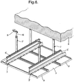
- the suspension device 7 is connected to the structural ceiling (see Figure 6 ) by means of the bracket assembly 9.
- the stiffening element 5 is connected to the panel carrier 3 by means of a spreading nut assembly 23 (see Figures 2 and 5 ) . Then the stiffening element 5 with the panel carrier 3 is connected to the suspension device 7.
- the structural ceiling is provided with as many of the panel carriers 3 as required, finally the ceiling panels (see figure 6 ) are installed to the panel carriers.
- the stiffening element serves as an integral rigidifier for the ceiling assembly.
- the panel carrier 3 as shown in figure 1 is known from EP 633365 B of Hunter Douglas , and will not be described in detail.
- the carrier includes a body 13 with a top wall 15 and two depending flanges 17 on either side thereof.
- the flanges 17 include means for holding the ceiling panels which are in the shape of hooked lugs 19 and locking lugs 21.
- the stiffening element 5 is connected to and along length of the top wall 15 of the panel carrier body 13 by means of one or more expanding nut assemblies 23 projecting through an opening 15A in the top wall (not shown) from the underside of the top wall of the panel carrier 3.
- the opening 15A is preferably an existing opening for mounting the panel carrier directly to a suspending device when used in a ceiling system without the stiffening element.
- the spreading nut assembly 23 can be seen connected to the panel carrier in Figure 2 and by itself in Figures 2 and 5 .
- the stiffening element 5 is an elongated I-shaped profile including a body 25 having opposite longitudinally extending front and rear faces 25A, 25B and a pair of open top- and bottom channels 27, 29.
- the top channel 27 is configured to be suspended from the bottom part of the suspension device 7.
- the top channel 27 thus has a bottom wall 31 perpendicular to the stiffener body 25 and centered with respect thereto such that the bottom wall 31 projects outwardly with respect to the longitudinal opposite faces 25A, 25B of the stiffener body 25 with a front and rear bottom wall sections 31A, 31B.
- Front and rear channel walls 33, 35 project perpendicularly and upwardly from the bottom wall sections 31A, 31B, thus extending generally parallel to the plane of the stiffener body.
- Each front and rear channel wall 33, 35 includes an inwardly angled top section 33A and 35B said sections extending parallel to the bottom channel wall 31.
- the channel walls and sections thus define the top channel 27 as a open-top channel with an elongated internal space 37 and an elongated entrance 37A.
- the bottom channel 29 of the stiffening element is configured to be attached to the panel carrier 3 by the spreading nut assembly 23.
- the bottom channel has a front and rear wall 39, 41 which project downward from the lower end of the stiffener body 25.
- a first section of the bottom channel's front and rear walls 39A, 41A diverge and form an inverted V-cross-section.
- the bottom channel's front and rear walls 39B, 41B are parallel to each other and to the plane of the stiffener body 25.
- the lower ends of the bottom channel's front and rear walls 39, 41 are provided with front and rear wall feet 43, 45.
- the feet extend generally horizontal and parallel to the bottom wall 31 of the top channel 27.
- the soles 43A,45A of the feet provide a support base for the stiffening element 5 to rest atop the top wall 15 of the panel carrier 3, and the heels 43B,45B of the feet 43, 45 provide an engagement surface for the spreading nut assembly 23 when connection the panel carrier 3 to the stiffening element 5 .
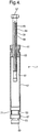
- the suspension device 7 as best visible in Figure 4 , preferably is a length adjustable member with a hollow tubular body 47 and a threaded bolt 49.
- the tubular body 47 is closed at top end by a hollow internally threaded nut 51 and at the bottom end with an end plug 53, preferably by swaging.
- the tube body 47 is rotatably connected by means of the internally threaded nut 51 to the elongated externally threaded bolt 49. By rotation of the tube 47 its position relative to the threaded bolt 49 is changed and the overall length of the suspension member 7 is increased or reduced.
- the length of the threaded bolt 49 is necessarily always less than the length of the tubular body 47 and it defines the scope of the length adjustability of the suspension member 5.
- the threaded bolt 49 of the suspension device 7 has a stem 55 and a head 57, the stem 55 includes a main upper threaded portion 59 and a lower unthreaded portion 61.
- the external screw 59 thread of the stem 55 of the bolt 49 cooperates with the internal screw thread 63 of the threaded nut 51.
- the external thread 59 is provided with a narrow elongated locking strip 65 along its length.
- the locking strip 65 prevents unintentional rotation of the tubular body 47 relative to the bolt 49 , i.e. under influence of weight or vibrations of the ceiling assembly.
- the head 57 of the threaded bolt is preferably a hexagonal head for cooperation with the bracket assembly 9 for mounting the suspension device to the structural ceiling.
- the end plug 53 for the bottom of the tubular body 49 includes a body 67 and a connector 69.
- the body 67 has a waist 71 to facilitate the swaging procedure and is inserted completely into tubular body 47.
- the connector 69 integrally connected to the body below a second waist 73 and projects, together with the second waist 73, outside of the tubular body 47.
- the connector 69 is encompassed by top channel 27 of the stiffener element 5.
- the inwardly angled top sections 31A and 33B grip the second wais 73 of the end plug 53, while allowing slidable and rotational movement of the tubular body 47 of the suspension device 7 relative to the stiffening profile 5. Both such movements are convenient when assembling and installing the ceiling assembly parts to each other and to the structural ceiling.
- the expanding nut assembly 23 is best visible in figure 5 , and includes an expandable nut 77 and a screw 79.
- the expandable nut 77 has a generally rectangular base 81 with a cylindrical extension 83, and a gripping head or expanding head 85.
- the expanding head has at least two tongues 87 which are separated by an axial slot 89 and the tongues have exterior wedge faces 91 with horizontal wedge edges 91A.
- a threaded channel 93 is formed through the cylindrical extension 83 and the base 81.
- the rectangular base 81 positions the nut 77 relative to the carrier top wall 15.
- the screw 79 is then inserted into the threaded channel 93 and turned.
- the thickness of the stem 95 spreads the tongues 87 of the head. This expansion of the tongues allows the wedge edges 91A to grip the heels 43B, 45B of the bottom channel 29 of the stiffener profile 5, thus securing these parts together.
- FIG. 6 illustrates a portion of the ceiling assembly 1 of the invention in use suspended from structural ceiling A, the assembly is shown with several ceiling panels P installed to several panel carriers 3. A pair of a panel carriers 3, 3' extending parallel to each other and each equipped with elongated stiffening element 5, 5' fixed atop the carrier and along its length. Further each panel carrier-stiffener combination is suspended from the structural ceiling by means of a pair of length adjustable suspension devices 7, 7' and bracket assembly 9.
- FIGS 7A-7D show alternative panel carriers in the description of which like parts are numbered with corresponding referral numbers as the panel carrier previously described, greater by 100, 200, 300 and 400.
- Each of the alternative carriers 103, 203, 303, 403 include a body 113, 213, 313, 413 with a top wall 115, 215, 315, 415 and two depending flanges 117, 217, 317, 417 on either side thereof.
- the openings 115A, 215A, 315A, 415A shown in the top walls 115, 215, 315, 415 of the alternative panel carriers 103, 203, 303, 403 are standard openings, but can be used for inserting the spreading nut assembly 23 in order to attach the stiffening element 5 to the top wall.
- the flanges 117, 217 of the carriers 103, 203 of Figures 7B and 7B include hooked lugs 119, 217 for mounting a ceiling panel.
- the flanges 317, 417 of the carriers 303, 403 are provided at the bottom edge of thereof with horizontal outwardly projecting front and rear bottom edge-flanges 397, 497. These bottom edge flanges are provided with panel mounting means 399, 499.
- the spreading nut assembly 23 can be used to connect the stiffener 5 to the top wall 115, 215, 315, 415.
Landscapes
- Engineering & Computer Science (AREA)
- Architecture (AREA)
- Physics & Mathematics (AREA)
- Electromagnetism (AREA)
- Civil Engineering (AREA)
- Structural Engineering (AREA)
- Building Environments (AREA)
- Body Structure For Vehicles (AREA)
Claims (9)
- Zwischendeckenanordnung (1), umfassend mindestens einen Plattenträger (3, 103, 203, 303, 403), mindestens eine Aufhängevorrichtung (7) und mindestens ein erstes Versteifungsmittel (5), wobei:die Aufhängevorrichtung (7) eine längenverstellbare Vorrichtung ist;der mindestens eine Plattenträger (3, 103, 203, 303, 403) eine obere Wand (15, 115,215,315,415) und eine Öffnung (15A, 115A, 215A, 315A, 415A) in der oberen Wand (15, 115, 215, 315, 415) zum direkten Befestigen des Plattenträgers (3, 103, 203, 303, 403) an einer Aufhängevorrichtung bei Verwendung ohne das Versteifungsmittel (5) umfasst; unddas mindestens eine erste Versteifungsmittel ein längliches Aussteifungselement (5) ist, das oben auf dem mindestens einen Plattenträger (3, 103, 203, 303, 403) entlang seiner Länge befestigt ist,das mindestens eine erste Versteifungsmittel (5) mit dem mindestens einen Plattenträger (3, 103, 203, 303, 403) und der mindestens einen Aufhängevorrichtung (7) verbunden ist, sodass das mindestens eine erste Versteifungsmittel (5) zwischen dem mindestens einen Plattenträger (3, 103, 203, 303, 403) und der mindestens einen Aufhängevorrichtung (7) eingefügt ist, dadurch gekennzeichnet, dass das mindestens eine erste Versteifungsmittel (5) oben auf dem mindestens einen Plattenträger (3, 103, 203, 303, 403) mittels einer oder mehrerer Spreizmutteranordnungen (23) befestigt ist, die durch die Öffnung (15A, 115A, 215A, 315A, 415A) in der oberen Wand des Plattenträgers vorstehen.
- Deckenanordnung nach Anspruch 1, ferner umfassend mindestens ein zweites Versteifungsmittel, und wobei das mindestens eine zweite Versteifungsmittel (7) eine Aufhängevorrichtung umfasst.
- Deckenanordnung nach Anspruch 1 oder 2, wobei das längliche Aussteifungselement ein generell 1-förmiges Profil ist und an gegenüberliegenden oberen und unteren Längen zur Befestigung an dem Plattenträger (3, 102, 203, 303, 403) und der Aufhängevorrichtung (7) mit Befestigungsmitteln (27, 29) versehen ist.
- Deckenanordnung nach Anspruch 3, wobei die Befestigungsmittel des Aussteifungselements ein U-förmiges oberes Profil (27) umfassen.
- Deckensystem nach einem der Ansprüche 2 bis 4, wobei die Aufhängevorrichtung ein rohrförmiges Element (47) umfasst.
- Deckensystem nach Anspruch 5, wobei die Aufhängevorrichtung ferner einen Gewindebolzen (49) umfasst und das rohrförmige Element (47) mit dem Bolzen drehbar verbunden ist, sodass ein Drehen des rohrförmigen Elements seine Position relativ zu dem Bolzen ändert und daher die Gesamtlänge des Aufhängeelements vergrößert oder verkleinert.
- Deckensystem nach einem der vorstehenden Ansprüche, wobei die Aufhängevorrichtung verschiebbar und entlang dem Aussteifungselement drehbar ist.
- Deckensystem nach einem der vorstehenden Ansprüche, wobei mehrere Plattenträger parallel und voneinander beabstandet zueinander aufgehängt sind und mindestens eine längliche Deckenplatte mit den mindestens zwei parallelen Plattenträgern in einer zur Länge der Plattenträger senkrechten Richtung verbindbar ist.
- Kit-Of-Parts für eine Zwischendeckenanordnung, wobei das Kit-Of-Parts mindestens einen Plattenträger (3, 103, 203, 303, 403), mindestens eine Aufhängevorrichtung (7), eine oder mehrere Spreizmutteranordnungen (23) und das mindestens eine erste Versteifungsmittel (5) umfasst, wobei:die Aufhängevorrichtung (7) eine längenverstellbare Vorrichtung ist;der mindestens eine Plattenträger (3, 103, 203, 303, 403) eine obere Wand (15, 115,215,315,415) und eine Öffnung (15A, 115A, 215A, 315A, 415A) in der oberen Wand (15, 115, 215, 315, 415) zum direkten Befestigen des Plattenträgers (3, 103, 203, 303, 403) an einer Aufhängevorrichtung bei Verwendung ohne das Versteifungsmittel (5) umfasst; unddas mindestens eine erste Versteifungsmittel ein längliches Aussteifungselement (5) ist, das konfiguriert ist, oben auf dem mindestens einen Plattenträger (3, 103, 203, 303, 403) entlang seiner Länge befestigt zu werden,wobei das mindestens eine erste Versteifungsmittel (5) für eine Verbindung mit und eine Einfügung zwischen dem mindestens einen Plattenträger (3, 103, 203, 303, 403) und der mindestens einen Aufhängevorrichtung (7) angepasst ist, dadurch gekennzeichnet, dass das mindestens eine erste Versteifungsmittel (5) konfiguriert ist, oben auf dem mindestens einen Plattenträger (3, 103, 203, 303, 403) mittels der einen oder der mehreren Spreizmutteranordnungen (23), die durch die Öffnung (15A, 115A, 215A, 315A, 415A) in der oberen Wand des Plattenträgers vorstehen, befestigt zu werden.
Priority Applications (1)
| Application Number | Priority Date | Filing Date | Title |
|---|---|---|---|
| EP09251063.5A EP2110488B1 (de) | 2008-04-14 | 2009-04-09 | Deckenanordnung |
Applications Claiming Priority (2)
| Application Number | Priority Date | Filing Date | Title |
|---|---|---|---|
| EP08007268 | 2008-04-14 | ||
| EP09251063.5A EP2110488B1 (de) | 2008-04-14 | 2009-04-09 | Deckenanordnung |
Publications (3)
| Publication Number | Publication Date |
|---|---|
| EP2110488A2 EP2110488A2 (de) | 2009-10-21 |
| EP2110488A3 EP2110488A3 (de) | 2014-02-19 |
| EP2110488B1 true EP2110488B1 (de) | 2018-08-29 |
Family
ID=40940664
Family Applications (1)
| Application Number | Title | Priority Date | Filing Date |
|---|---|---|---|
| EP09251063.5A Active EP2110488B1 (de) | 2008-04-14 | 2009-04-09 | Deckenanordnung |
Country Status (1)
| Country | Link |
|---|---|
| EP (1) | EP2110488B1 (de) |
Families Citing this family (3)
| Publication number | Priority date | Publication date | Assignee | Title |
|---|---|---|---|---|
| FR3043111B1 (fr) * | 2015-10-28 | 2019-08-30 | Saint-Gobain Isover | Dispositif d'entretoisement pour le doublage d'une structure |
| AU2021421274B2 (en) * | 2021-01-25 | 2023-06-15 | Sasan SAIDIAN | Seismic restraint of ceilings |
| FR3147579B1 (fr) | 2023-04-07 | 2025-02-21 | Mehmet Demirbas | Dispositif d’entretoisement pour le doublage d’une structure |
Family Cites Families (5)
| Publication number | Priority date | Publication date | Assignee | Title |
|---|---|---|---|---|
| NL7003811A (de) * | 1970-03-18 | 1971-09-21 | ||
| DE2162382A1 (de) * | 1971-12-16 | 1973-06-20 | Westag & Getalit Ag | Vorrichtung fuer die aufhaengung einer deckenverkleidung an ortsfesten gebaeudedecken |
| FR2589907B1 (fr) * | 1985-11-07 | 1988-08-12 | Placoplatre Sa | Suspente pour faux-plafond. |
| ES2109609T3 (es) | 1993-07-09 | 1998-01-16 | Hunter Douglas Ind Bv | Un sistema de paneles y un larguero de soporte para los mismos. |
| DE4412043C2 (de) * | 1994-04-08 | 2001-08-16 | Kab Koch Deckensysteme Gmbh & | Profilrasterdecke für Wohn-, Geschäfts-, Ausstellungsräume o. dgl. |
-
2009
- 2009-04-09 EP EP09251063.5A patent/EP2110488B1/de active Active
Non-Patent Citations (1)
| Title |
|---|
| None * |
Also Published As
| Publication number | Publication date |
|---|---|
| EP2110488A3 (de) | 2014-02-19 |
| EP2110488A2 (de) | 2009-10-21 |
Similar Documents
| Publication | Publication Date | Title |
|---|---|---|
| EP2843145B1 (de) | Deckensystem mit Elementmontageklammern | |
| US7654495B2 (en) | Hanger assembly | |
| EP2103753B1 (de) | Oberflächenabdeckung und Befestigungssystem | |
| US20150376900A1 (en) | Partition Wall System Including Clamping of the Panels | |
| EP2961905B1 (de) | Trennwandsystem mit einklemmprofil | |
| EA036648B1 (ru) | Безанкерная система крепления облицовочных панелей и способ ее крепления | |
| EP2110488B1 (de) | Deckenanordnung | |
| KR102459898B1 (ko) | 커튼봉 고정장치 | |
| KR20100107103A (ko) | 강성이 보강된 커튼월 | |
| JP2018062853A (ja) | 天井下地構造 | |
| KR20150000296U (ko) | 글라스 커튼월용 유리 고정장치 | |
| WO2021079132A1 (en) | Wall system | |
| JP4255407B2 (ja) | 庇の取付け構造 | |
| KR101711556B1 (ko) | 칸막이 판넬과 도어 설치용 고정 프레임 | |
| KR20090008675U (ko) | 시스템 창호용 지지앵커 지지대 | |
| KR101336668B1 (ko) | 트러스 조립체 | |
| KR100191351B1 (ko) | 달반자 구조 | |
| KR200207355Y1 (ko) | 천정부재의 조립성을 향상한 행거 구조물 | |
| JP4763930B2 (ja) | 天井板固定枠を使用した天井構造 | |
| KR20170018147A (ko) | 내장재 고정용 클립 | |
| WO2024178411A1 (en) | Bar hanger assembly | |
| JP3841662B2 (ja) | 屋外通路 | |
| JP7548738B2 (ja) | パネル体への把持部材の取り付け構造 | |
| SK117799A3 (en) | Profile rail and coupling element of supporting device | |
| CZ65996A3 (en) | Front panel wall |
Legal Events
| Date | Code | Title | Description |
|---|---|---|---|
| PUAI | Public reference made under article 153(3) epc to a published international application that has entered the european phase |
Free format text: ORIGINAL CODE: 0009012 |
|
| AK | Designated contracting states |
Kind code of ref document: A2 Designated state(s): AT BE BG CH CY CZ DE DK EE ES FI FR GB GR HR HU IE IS IT LI LT LU LV MC MK MT NL NO PL PT RO SE SI SK TR |
|
| PUAL | Search report despatched |
Free format text: ORIGINAL CODE: 0009013 |
|
| AK | Designated contracting states |
Kind code of ref document: A3 Designated state(s): AT BE BG CH CY CZ DE DK EE ES FI FR GB GR HR HU IE IS IT LI LT LU LV MC MK MT NL NO PL PT RO SE SI SK TR |
|
| AX | Request for extension of the european patent |
Extension state: AL BA RS |
|
| RIC1 | Information provided on ipc code assigned before grant |
Ipc: E04B 9/20 20060101ALI20140113BHEP Ipc: E04B 9/06 20060101AFI20140113BHEP |
|
| RBV | Designated contracting states (corrected) |
Designated state(s): AT BE BG CH CY CZ DE DK EE ES FI FR GB GR HR HU IE IS IT LI LT LU LV MC MK MT NL NO PL PT RO SE SI SK TR |
|
| 17P | Request for examination filed |
Effective date: 20140819 |
|
| 17Q | First examination report despatched |
Effective date: 20150325 |
|
| STAA | Information on the status of an ep patent application or granted ep patent |
Free format text: STATUS: EXAMINATION IS IN PROGRESS |
|
| GRAP | Despatch of communication of intention to grant a patent |
Free format text: ORIGINAL CODE: EPIDOSNIGR1 |
|
| STAA | Information on the status of an ep patent application or granted ep patent |
Free format text: STATUS: GRANT OF PATENT IS INTENDED |
|
| INTG | Intention to grant announced |
Effective date: 20180312 |
|
| GRAS | Grant fee paid |
Free format text: ORIGINAL CODE: EPIDOSNIGR3 |
|
| GRAA | (expected) grant |
Free format text: ORIGINAL CODE: 0009210 |
|
| STAA | Information on the status of an ep patent application or granted ep patent |
Free format text: STATUS: THE PATENT HAS BEEN GRANTED |
|
| AK | Designated contracting states |
Kind code of ref document: B1 Designated state(s): AT BE BG CH CY CZ DE DK EE ES FI FR GB GR HR HU IE IS IT LI LT LU LV MC MK MT NL NO PL PT RO SE SI SK TR |
|
| REG | Reference to a national code |
Ref country code: GB Ref legal event code: FG4D |
|
| REG | Reference to a national code |
Ref country code: CH Ref legal event code: EP |
|
| REG | Reference to a national code |
Ref country code: AT Ref legal event code: REF Ref document number: 1035298 Country of ref document: AT Kind code of ref document: T Effective date: 20180915 |
|
| REG | Reference to a national code |
Ref country code: IE Ref legal event code: FG4D |
|
| REG | Reference to a national code |
Ref country code: DE Ref legal event code: R096 Ref document number: 602009054135 Country of ref document: DE |
|
| REG | Reference to a national code |
Ref country code: NL Ref legal event code: FP |
|
| REG | Reference to a national code |
Ref country code: LT Ref legal event code: MG4D |
|
| PG25 | Lapsed in a contracting state [announced via postgrant information from national office to epo] |
Ref country code: LT Free format text: LAPSE BECAUSE OF FAILURE TO SUBMIT A TRANSLATION OF THE DESCRIPTION OR TO PAY THE FEE WITHIN THE PRESCRIBED TIME-LIMIT Effective date: 20180829 Ref country code: NO Free format text: LAPSE BECAUSE OF FAILURE TO SUBMIT A TRANSLATION OF THE DESCRIPTION OR TO PAY THE FEE WITHIN THE PRESCRIBED TIME-LIMIT Effective date: 20181129 Ref country code: IS Free format text: LAPSE BECAUSE OF FAILURE TO SUBMIT A TRANSLATION OF THE DESCRIPTION OR TO PAY THE FEE WITHIN THE PRESCRIBED TIME-LIMIT Effective date: 20181229 Ref country code: FI Free format text: LAPSE BECAUSE OF FAILURE TO SUBMIT A TRANSLATION OF THE DESCRIPTION OR TO PAY THE FEE WITHIN THE PRESCRIBED TIME-LIMIT Effective date: 20180829 Ref country code: SE Free format text: LAPSE BECAUSE OF FAILURE TO SUBMIT A TRANSLATION OF THE DESCRIPTION OR TO PAY THE FEE WITHIN THE PRESCRIBED TIME-LIMIT Effective date: 20180829 Ref country code: GR Free format text: LAPSE BECAUSE OF FAILURE TO SUBMIT A TRANSLATION OF THE DESCRIPTION OR TO PAY THE FEE WITHIN THE PRESCRIBED TIME-LIMIT Effective date: 20181130 Ref country code: BG Free format text: LAPSE BECAUSE OF FAILURE TO SUBMIT A TRANSLATION OF THE DESCRIPTION OR TO PAY THE FEE WITHIN THE PRESCRIBED TIME-LIMIT Effective date: 20181129 |
|
| REG | Reference to a national code |
Ref country code: AT Ref legal event code: MK05 Ref document number: 1035298 Country of ref document: AT Kind code of ref document: T Effective date: 20180829 |
|
| PG25 | Lapsed in a contracting state [announced via postgrant information from national office to epo] |
Ref country code: LV Free format text: LAPSE BECAUSE OF FAILURE TO SUBMIT A TRANSLATION OF THE DESCRIPTION OR TO PAY THE FEE WITHIN THE PRESCRIBED TIME-LIMIT Effective date: 20180829 Ref country code: ES Free format text: LAPSE BECAUSE OF FAILURE TO SUBMIT A TRANSLATION OF THE DESCRIPTION OR TO PAY THE FEE WITHIN THE PRESCRIBED TIME-LIMIT Effective date: 20180829 Ref country code: HR Free format text: LAPSE BECAUSE OF FAILURE TO SUBMIT A TRANSLATION OF THE DESCRIPTION OR TO PAY THE FEE WITHIN THE PRESCRIBED TIME-LIMIT Effective date: 20180829 |
|
| PG25 | Lapsed in a contracting state [announced via postgrant information from national office to epo] |
Ref country code: RO Free format text: LAPSE BECAUSE OF FAILURE TO SUBMIT A TRANSLATION OF THE DESCRIPTION OR TO PAY THE FEE WITHIN THE PRESCRIBED TIME-LIMIT Effective date: 20180829 Ref country code: IT Free format text: LAPSE BECAUSE OF FAILURE TO SUBMIT A TRANSLATION OF THE DESCRIPTION OR TO PAY THE FEE WITHIN THE PRESCRIBED TIME-LIMIT Effective date: 20180829 Ref country code: CZ Free format text: LAPSE BECAUSE OF FAILURE TO SUBMIT A TRANSLATION OF THE DESCRIPTION OR TO PAY THE FEE WITHIN THE PRESCRIBED TIME-LIMIT Effective date: 20180829 Ref country code: PL Free format text: LAPSE BECAUSE OF FAILURE TO SUBMIT A TRANSLATION OF THE DESCRIPTION OR TO PAY THE FEE WITHIN THE PRESCRIBED TIME-LIMIT Effective date: 20180829 Ref country code: AT Free format text: LAPSE BECAUSE OF FAILURE TO SUBMIT A TRANSLATION OF THE DESCRIPTION OR TO PAY THE FEE WITHIN THE PRESCRIBED TIME-LIMIT Effective date: 20180829 Ref country code: EE Free format text: LAPSE BECAUSE OF FAILURE TO SUBMIT A TRANSLATION OF THE DESCRIPTION OR TO PAY THE FEE WITHIN THE PRESCRIBED TIME-LIMIT Effective date: 20180829 |
|
| PG25 | Lapsed in a contracting state [announced via postgrant information from national office to epo] |
Ref country code: SK Free format text: LAPSE BECAUSE OF FAILURE TO SUBMIT A TRANSLATION OF THE DESCRIPTION OR TO PAY THE FEE WITHIN THE PRESCRIBED TIME-LIMIT Effective date: 20180829 Ref country code: DK Free format text: LAPSE BECAUSE OF FAILURE TO SUBMIT A TRANSLATION OF THE DESCRIPTION OR TO PAY THE FEE WITHIN THE PRESCRIBED TIME-LIMIT Effective date: 20180829 |
|
| REG | Reference to a national code |
Ref country code: DE Ref legal event code: R097 Ref document number: 602009054135 Country of ref document: DE |
|
| PLBE | No opposition filed within time limit |
Free format text: ORIGINAL CODE: 0009261 |
|
| STAA | Information on the status of an ep patent application or granted ep patent |
Free format text: STATUS: NO OPPOSITION FILED WITHIN TIME LIMIT |
|
| 26N | No opposition filed |
Effective date: 20190531 |
|
| PG25 | Lapsed in a contracting state [announced via postgrant information from national office to epo] |
Ref country code: SI Free format text: LAPSE BECAUSE OF FAILURE TO SUBMIT A TRANSLATION OF THE DESCRIPTION OR TO PAY THE FEE WITHIN THE PRESCRIBED TIME-LIMIT Effective date: 20180829 |
|
| REG | Reference to a national code |
Ref country code: CH Ref legal event code: PL |
|
| PG25 | Lapsed in a contracting state [announced via postgrant information from national office to epo] |
Ref country code: LU Free format text: LAPSE BECAUSE OF NON-PAYMENT OF DUE FEES Effective date: 20190409 Ref country code: MC Free format text: LAPSE BECAUSE OF FAILURE TO SUBMIT A TRANSLATION OF THE DESCRIPTION OR TO PAY THE FEE WITHIN THE PRESCRIBED TIME-LIMIT Effective date: 20180829 |
|
| PG25 | Lapsed in a contracting state [announced via postgrant information from national office to epo] |
Ref country code: CH Free format text: LAPSE BECAUSE OF NON-PAYMENT OF DUE FEES Effective date: 20190430 Ref country code: LI Free format text: LAPSE BECAUSE OF NON-PAYMENT OF DUE FEES Effective date: 20190430 |
|
| PG25 | Lapsed in a contracting state [announced via postgrant information from national office to epo] |
Ref country code: TR Free format text: LAPSE BECAUSE OF FAILURE TO SUBMIT A TRANSLATION OF THE DESCRIPTION OR TO PAY THE FEE WITHIN THE PRESCRIBED TIME-LIMIT Effective date: 20180829 |
|
| PG25 | Lapsed in a contracting state [announced via postgrant information from national office to epo] |
Ref country code: IE Free format text: LAPSE BECAUSE OF NON-PAYMENT OF DUE FEES Effective date: 20190409 |
|
| PG25 | Lapsed in a contracting state [announced via postgrant information from national office to epo] |
Ref country code: PT Free format text: LAPSE BECAUSE OF FAILURE TO SUBMIT A TRANSLATION OF THE DESCRIPTION OR TO PAY THE FEE WITHIN THE PRESCRIBED TIME-LIMIT Effective date: 20181229 |
|
| PG25 | Lapsed in a contracting state [announced via postgrant information from national office to epo] |
Ref country code: CY Free format text: LAPSE BECAUSE OF FAILURE TO SUBMIT A TRANSLATION OF THE DESCRIPTION OR TO PAY THE FEE WITHIN THE PRESCRIBED TIME-LIMIT Effective date: 20180829 |
|
| PG25 | Lapsed in a contracting state [announced via postgrant information from national office to epo] |
Ref country code: MT Free format text: LAPSE BECAUSE OF FAILURE TO SUBMIT A TRANSLATION OF THE DESCRIPTION OR TO PAY THE FEE WITHIN THE PRESCRIBED TIME-LIMIT Effective date: 20180829 Ref country code: HU Free format text: LAPSE BECAUSE OF FAILURE TO SUBMIT A TRANSLATION OF THE DESCRIPTION OR TO PAY THE FEE WITHIN THE PRESCRIBED TIME-LIMIT; INVALID AB INITIO Effective date: 20090409 |
|
| PG25 | Lapsed in a contracting state [announced via postgrant information from national office to epo] |
Ref country code: MK Free format text: LAPSE BECAUSE OF FAILURE TO SUBMIT A TRANSLATION OF THE DESCRIPTION OR TO PAY THE FEE WITHIN THE PRESCRIBED TIME-LIMIT Effective date: 20180829 |
|
| P01 | Opt-out of the competence of the unified patent court (upc) registered |
Effective date: 20230331 |
|
| PGFP | Annual fee paid to national office [announced via postgrant information from national office to epo] |
Ref country code: NL Payment date: 20250424 Year of fee payment: 17 |
|
| PGFP | Annual fee paid to national office [announced via postgrant information from national office to epo] |
Ref country code: DE Payment date: 20250428 Year of fee payment: 17 |
|
| PGFP | Annual fee paid to national office [announced via postgrant information from national office to epo] |
Ref country code: GB Payment date: 20250422 Year of fee payment: 17 |
|
| PGFP | Annual fee paid to national office [announced via postgrant information from national office to epo] |
Ref country code: BE Payment date: 20250424 Year of fee payment: 17 |
|
| PGFP | Annual fee paid to national office [announced via postgrant information from national office to epo] |
Ref country code: FR Payment date: 20250424 Year of fee payment: 17 |