EP2110491A1 - Struktur und Ankersystem für belüftete Außenwandfliesen und Anordnung - Google Patents
Struktur und Ankersystem für belüftete Außenwandfliesen und Anordnung Download PDFInfo
- Publication number
- EP2110491A1 EP2110491A1 EP08380119A EP08380119A EP2110491A1 EP 2110491 A1 EP2110491 A1 EP 2110491A1 EP 08380119 A EP08380119 A EP 08380119A EP 08380119 A EP08380119 A EP 08380119A EP 2110491 A1 EP2110491 A1 EP 2110491A1
- Authority
- EP
- European Patent Office
- Prior art keywords
- assembly
- standard
- plates
- clamp
- clamp holder
- Prior art date
- Legal status (The legal status is an assumption and is not a legal conclusion. Google has not performed a legal analysis and makes no representation as to the accuracy of the status listed.)
- Withdrawn
Links
- 238000004873 anchoring Methods 0.000 claims abstract description 41
- 238000005253 cladding Methods 0.000 claims abstract description 37
- 239000002131 composite material Substances 0.000 claims abstract description 16
- 229910052500 inorganic mineral Inorganic materials 0.000 claims abstract description 16
- 239000011707 mineral Substances 0.000 claims abstract description 16
- 238000009434 installation Methods 0.000 claims abstract description 8
- 239000011810 insulating material Substances 0.000 claims abstract description 4
- 239000000463 material Substances 0.000 claims description 11
- 210000002105 tongue Anatomy 0.000 claims description 11
- 230000008878 coupling Effects 0.000 claims description 4
- 238000010168 coupling process Methods 0.000 claims description 4
- 238000005859 coupling reaction Methods 0.000 claims description 4
- 238000003825 pressing Methods 0.000 claims description 2
- 238000005259 measurement Methods 0.000 claims 1
- 239000002184 metal Substances 0.000 abstract description 4
- 239000011449 brick Substances 0.000 abstract description 3
- 239000000853 adhesive Substances 0.000 description 2
- 230000001070 adhesive effect Effects 0.000 description 2
- 208000007101 Muscle Cramp Diseases 0.000 description 1
- 229910000831 Steel Inorganic materials 0.000 description 1
- 238000000034 method Methods 0.000 description 1
- 238000009428 plumbing Methods 0.000 description 1
- 239000010959 steel Substances 0.000 description 1
Images





Classifications
-
- E—FIXED CONSTRUCTIONS
- E04—BUILDING
- E04F—FINISHING WORK ON BUILDINGS, e.g. STAIRS, FLOORS
- E04F13/00—Coverings or linings, e.g. for walls or ceilings
- E04F13/07—Coverings or linings, e.g. for walls or ceilings composed of covering or lining elements; Sub-structures therefor; Fastening means therefor
- E04F13/08—Coverings or linings, e.g. for walls or ceilings composed of covering or lining elements; Sub-structures therefor; Fastening means therefor composed of a plurality of similar covering or lining elements
- E04F13/0801—Separate fastening elements
- E04F13/0803—Separate fastening elements with load-supporting elongated furring elements between wall and covering elements
- E04F13/0805—Separate fastening elements with load-supporting elongated furring elements between wall and covering elements with additional fastening elements between furring elements and the wall
- E04F13/0808—Separate fastening elements with load-supporting elongated furring elements between wall and covering elements with additional fastening elements between furring elements and the wall adjustable in several directions one of which is perpendicular to the wall
-
- E—FIXED CONSTRUCTIONS
- E04—BUILDING
- E04F—FINISHING WORK ON BUILDINGS, e.g. STAIRS, FLOORS
- E04F13/00—Coverings or linings, e.g. for walls or ceilings
- E04F13/07—Coverings or linings, e.g. for walls or ceilings composed of covering or lining elements; Sub-structures therefor; Fastening means therefor
- E04F13/08—Coverings or linings, e.g. for walls or ceilings composed of covering or lining elements; Sub-structures therefor; Fastening means therefor composed of a plurality of similar covering or lining elements
- E04F13/0801—Separate fastening elements
- E04F13/0803—Separate fastening elements with load-supporting elongated furring elements between wall and covering elements
- E04F13/081—Separate fastening elements with load-supporting elongated furring elements between wall and covering elements with additional fastening elements between furring elements and covering elements
- E04F13/0814—Separate fastening elements with load-supporting elongated furring elements between wall and covering elements with additional fastening elements between furring elements and covering elements fixed by means of clamping action
-
- E—FIXED CONSTRUCTIONS
- E04—BUILDING
- E04F—FINISHING WORK ON BUILDINGS, e.g. STAIRS, FLOORS
- E04F13/00—Coverings or linings, e.g. for walls or ceilings
- E04F13/07—Coverings or linings, e.g. for walls or ceilings composed of covering or lining elements; Sub-structures therefor; Fastening means therefor
- E04F13/08—Coverings or linings, e.g. for walls or ceilings composed of covering or lining elements; Sub-structures therefor; Fastening means therefor composed of a plurality of similar covering or lining elements
- E04F13/0801—Separate fastening elements
- E04F13/0803—Separate fastening elements with load-supporting elongated furring elements between wall and covering elements
- E04F13/081—Separate fastening elements with load-supporting elongated furring elements between wall and covering elements with additional fastening elements between furring elements and covering elements
- E04F13/0821—Separate fastening elements with load-supporting elongated furring elements between wall and covering elements with additional fastening elements between furring elements and covering elements the additional fastening elements located in-between two adjacent covering elements
- E04F13/0826—Separate fastening elements with load-supporting elongated furring elements between wall and covering elements with additional fastening elements between furring elements and covering elements the additional fastening elements located in-between two adjacent covering elements engaging side grooves running along the whole length of the covering elements
Definitions
- the invention relates to a metal structure, an anchoring system for cladding plates made of different materials and a way of installing both for making lightweight ventilated façades.
- the metal structure is basically formed by vertical tubular load-bearing structures which are fixed to the building by means of specific anchoring elements and cramps in the shape of a clamp which allows adjusting the point for securing the plates along three axes in their standard installation and along five axes in their particular installation.
- the plates which can be made of different materials, have a profile which is pressure housed inside the clamps, being firmly secured without needing screws, rivets or adhesives.
- the advantageous usefulness of the invention is that of providing an adjustable structure along three or five axes, formed only by vertical load-bearing structures with a system for adjustably fixing the load-bearing structure to the building and a system of adjustable clamps for securing the cladding plates which are assembled under pressure without needing adhesives, rivets or screws allowing to easily put the plates on again.
- a second element is two latches, one on each side of the work anchoring base for the provisional positioning of the vertical load-bearing structure which are clipped on the anchoring base and which are used for securing during the process of laying out the vertical load-bearing structure and once it is plumbed it is definitively fixed by screws.
- Another element of the structure is the vertical load-bearing structure made in a metal profile provided with three longitudinal tracks, two side tracks in its rear part for their fixing on the anchoring base by means of the positioning latches and another front track for placing the clamp holder base as well as a rear channel in which an insulating material is coupled.
- This system for installing the vertical load-bearing structure offers the possibility of adding anchoring bases according to the needs of the work without having to disassemble the already installed elements.
- There are two variants of the securing assembly of the plate which are the securing assembly for a standard installation of a planar façade and the securing assembly for a three-dimensional installation with their respective clamp models for composite plates and mineral plates.
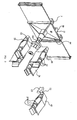
- the standard securing assembly of the plate is formed by three elements: the clamp for the composite plate or the clamp for the mineral plate, the standard clamp holders and the clamp holder base, in which the clamps, with a maximum of four and a minimum of two according to the needs, are introduced into the channels of the standard clamp holder, individually moving horizontally in order to adjust to the position of the plate.
- the three-dimensional clamps for a composite plate or mineral plate, the clamp holder ball joint and the clamp holder base are used, achieving, with a maximum of four and a minimum of two clamps according to the needs, together with the clamp holder ball joint, a total of four movement axes.
- Both variants have the clamp holder base in common, which is provided with clipping teeth for inserting the complete clamping assembly in the front track of the vertical load-bearing structure, being able to move vertically in its two variants, adjusting to the height of the plate, and definitively being fixed to the vertical load-bearing structure with a screw.
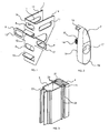
- the U-shaped work anchoring base (1) ( Figure 1 ) is installed directly on the work and can be assembled in three different ways according to the requirements of the work, either it is assembled by means of two screws or plugs which are housed in the boreholes (8) located in the vertical plane (13) of the bottom of the U, or two extended tabs (9) are used, which tabs are coplanar with the wall of the work, for fixing it with screws or plugs by means of the boreholes (12) provided for such purpose, or extending the two flanges (10) located in the vertical plane (13) of the bottom of the U in order to be able to install it by inserting it in grooved bricks.
- the positioning latch (2) of Figure 2 which is used for a pre-installation of the vertical load-bearing structure (3) on the already installed anchoring base (1), has a T-shaped catch (15) which enters, by rotating it 90°, in the vertical tracks (21) of the load-bearing structure (3) ( Figure 3 ) and which is slid to the anchoring base (1) in which, by pressing on the plane (18), its tenon (20) provided with teeth (16) is inserted in the lips (23) of the track (21) through the eyelet (11) of the anchoring base (1), placing the plane (19) against the side wings (14) of the anchoring base (1) and leaving the pre-installed load-bearing structure (3).
- the eyelet (11) of the anchoring base (1) allows the load-bearing structure (3) to move perpendicularly to the vertical plane of the work in order to achieve the plumbing of the latter, finally being firmly fixed by a screw (47) ( Figure 4 ) which is housed and guided in the borehole (17) of the latch (2) shown in Figure 2 .
- the load-bearing structure (3) has an insulating material (4) between the two tracks (21) in its rear part. This system for fixing the load-bearing structure (3) allows installing more anchoring bases (1) as the work progresses.
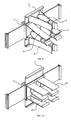
- the standard clamp (5) ( Figure 5 ) for a composite material cladding plate (42) ( Figure 11 ) has a plane (24) with two lips (38) projecting above the tongues (26) in order to be introduced in a vertical position in the groove (37) and in a horizontal position in the two grooves (29) of the standard clamp holder (6) ( Figure 7 ) allowing horizontal movement in both cases in order to find the perfect coupling of the composite material cladding plate (42) provided with grooves (43) which are clipped in the teeth (27) ( Figure 11 ).
- the elliptical segment (25) joining the two tongues (26) together acts as a spring and keeps the composite material cladding plate (42) pressed between the two tongues (26).
- the standard clamp (41) ( Figure 6 ) for a mineral material cladding plate (50) ( Figure 12 ) has a plane (24) with two lips (38) projecting above the tongues (48) in order to be introduced in a vertical position in the groove (37) of the standard clamp holder (6) ( Figure 7 ) allowing horizontal movement in order to find the perfect coupling of the mineral material cladding plate (50) provided with grooves (51) which are clipped in the teeth (40) ( Figure 12 ).
- the rib (57) joining the two tongues (48) together acts as a spring and keeps the mineral material cladding plate (50) pressed between the two tongues (48).
- the clamp holder base (7) is provided with two wings (55), which may or may not bend, ending with a three-toothed part (56) in order to secure insulating panels within the ventilated façade.
Landscapes
- Engineering & Computer Science (AREA)
- Architecture (AREA)
- Civil Engineering (AREA)
- Structural Engineering (AREA)
- Finishing Walls (AREA)
Priority Applications (1)
| Application Number | Priority Date | Filing Date | Title |
|---|---|---|---|
| EP08380119A EP2110491A1 (de) | 2008-04-18 | 2008-04-18 | Struktur und Ankersystem für belüftete Außenwandfliesen und Anordnung |
Applications Claiming Priority (1)
| Application Number | Priority Date | Filing Date | Title |
|---|---|---|---|
| EP08380119A EP2110491A1 (de) | 2008-04-18 | 2008-04-18 | Struktur und Ankersystem für belüftete Außenwandfliesen und Anordnung |
Publications (1)
| Publication Number | Publication Date |
|---|---|
| EP2110491A1 true EP2110491A1 (de) | 2009-10-21 |
Family
ID=39694241
Family Applications (1)
| Application Number | Title | Priority Date | Filing Date |
|---|---|---|---|
| EP08380119A Withdrawn EP2110491A1 (de) | 2008-04-18 | 2008-04-18 | Struktur und Ankersystem für belüftete Außenwandfliesen und Anordnung |
Country Status (1)
| Country | Link |
|---|---|
| EP (1) | EP2110491A1 (de) |
Cited By (6)
| Publication number | Priority date | Publication date | Assignee | Title |
|---|---|---|---|---|
| EP2500490A1 (de) | 2011-03-14 | 2012-09-19 | Abaco Solutions S.r.l. | Bauverfahren für eine belüftete Fassade |
| US8769901B2 (en) | 2010-05-28 | 2014-07-08 | The Diller Corporation | Cladding system for building laminates |
| ITTV20130092A1 (it) * | 2013-06-08 | 2014-12-09 | Abaco Solutions Srl | Facciata ventilata |
| JP2020511607A (ja) * | 2017-03-21 | 2020-04-16 | ジョーウン−デコ カンパニー リミテッドJoeun−Deco Co.,Ltd | 仕上げパネル固定装置 |
| EP4089250A1 (de) * | 2021-05-10 | 2022-11-16 | Sistemas Avanzados de Fachadas Ventiladas, S.L. | Belüftetes fassadenbefestigungssystem |
| CN116950343A (zh) * | 2023-07-28 | 2023-10-27 | 佛山欧神诺陶瓷有限公司 | 一种岩板安装结构及方法 |
Citations (2)
| Publication number | Priority date | Publication date | Assignee | Title |
|---|---|---|---|---|
| EP0374970A1 (de) * | 1988-12-23 | 1990-06-27 | MBS GeMont AG | Vorrichtung zur Verkleidung eines Baukörpers im Fassaden- und/oder Dachbereich |
| EP0605988A2 (de) | 1993-01-06 | 1994-07-13 | Hunter Douglas Industries B.V. | Eine Abfangvorrichtung |
-
2008
- 2008-04-18 EP EP08380119A patent/EP2110491A1/de not_active Withdrawn
Patent Citations (2)
| Publication number | Priority date | Publication date | Assignee | Title |
|---|---|---|---|---|
| EP0374970A1 (de) * | 1988-12-23 | 1990-06-27 | MBS GeMont AG | Vorrichtung zur Verkleidung eines Baukörpers im Fassaden- und/oder Dachbereich |
| EP0605988A2 (de) | 1993-01-06 | 1994-07-13 | Hunter Douglas Industries B.V. | Eine Abfangvorrichtung |
Cited By (7)
| Publication number | Priority date | Publication date | Assignee | Title |
|---|---|---|---|---|
| US8769901B2 (en) | 2010-05-28 | 2014-07-08 | The Diller Corporation | Cladding system for building laminates |
| US8991127B2 (en) | 2010-05-28 | 2015-03-31 | The Diller Corporation | Cladding system for building laminates |
| EP2500490A1 (de) | 2011-03-14 | 2012-09-19 | Abaco Solutions S.r.l. | Bauverfahren für eine belüftete Fassade |
| ITTV20130092A1 (it) * | 2013-06-08 | 2014-12-09 | Abaco Solutions Srl | Facciata ventilata |
| JP2020511607A (ja) * | 2017-03-21 | 2020-04-16 | ジョーウン−デコ カンパニー リミテッドJoeun−Deco Co.,Ltd | 仕上げパネル固定装置 |
| EP4089250A1 (de) * | 2021-05-10 | 2022-11-16 | Sistemas Avanzados de Fachadas Ventiladas, S.L. | Belüftetes fassadenbefestigungssystem |
| CN116950343A (zh) * | 2023-07-28 | 2023-10-27 | 佛山欧神诺陶瓷有限公司 | 一种岩板安装结构及方法 |
Similar Documents
| Publication | Publication Date | Title |
|---|---|---|
| EP2683887B1 (de) | Klammern für ein mauersystem mit dünnen backsteinen | |
| CN105507461B (zh) | 一种轻质隔墙的轻钢龙骨基础结构系统及施工方法 | |
| US4073108A (en) | Method and apparatus for rigidly interconnected ceiling and wall construction | |
| US20200318358A1 (en) | Anchor-free system for fastening of cladding panels and a method of fastening thereof | |
| US9032684B2 (en) | Clips for thin brick wall system | |
| US20230069389A1 (en) | Cladding attachment devices, systems, and associated methods of manufacture and use | |
| CN103154393A (zh) | 展异的建筑结构改良 | |
| WO2009015041A2 (en) | System and method for mounting electrical devices | |
| KR101864175B1 (ko) | 신축조절이 용이한 공동주택용 실내 마감재 | |
| EP4334544B1 (de) | System zum befestigen von platten an einer wand | |
| WO2010008778A2 (en) | System and method for mounting electrical devices | |
| KR102114047B1 (ko) | 수직방향 위치 조정이 용이한 경량 벽체 구조 및 이의 시공방법 | |
| CN113931403B (zh) | 一种装配式整体卫浴、厨房主体结构安装工艺 | |
| US20120256063A1 (en) | Arrangement for positioning suspended profiled elements in dry construction | |
| CN113431289B (zh) | 一种集成线管的装饰板安装组件、装饰板结构及安装方法 | |
| WO2009034384A1 (en) | Adjustable noggings | |
| CN220451304U (zh) | 快装龙骨、调平龙骨组件以及装配式磁吸内装墙面系统 | |
| US9717348B2 (en) | Pass through shelf wall assembly | |
| CN115217283A (zh) | 一种墙面找平龙骨组件及其安装方法 | |
| JP7193290B2 (ja) | 壁つなぎ用治具及び外壁パネル部材 | |
| CN219909798U (zh) | 装配式踢脚线组件及装配式磁吸墙板系统 | |
| EP4650546A2 (de) | Gebäudeverkleidungssysteme | |
| US20260110170A1 (en) | Modular wall junctions bracket systems and methods | |
| CN117027312B (zh) | 一种岩板装配系统及装配方法 | |
| CN217998730U (zh) | 一种专用于硅酸钙装饰板材的安装结构 |
Legal Events
| Date | Code | Title | Description |
|---|---|---|---|
| PUAI | Public reference made under article 153(3) epc to a published international application that has entered the european phase |
Free format text: ORIGINAL CODE: 0009012 |
|
| 17P | Request for examination filed |
Effective date: 20080604 |
|
| AK | Designated contracting states |
Kind code of ref document: A1 Designated state(s): AT BE BG CH CY CZ DE DK EE ES FI FR GB GR HR HU IE IS IT LI LT LU LV MC MT NL NO PL PT RO SE SI SK TR |
|
| AX | Request for extension of the european patent |
Extension state: AL BA MK RS |
|
| AKX | Designation fees paid |
Designated state(s): AT BE BG CH CY CZ DE DK EE ES FI FR GB GR HR HU IE IS IT LI LT LU LV MC MT NL NO PL PT RO SE SI SK TR |
|
| STAA | Information on the status of an ep patent application or granted ep patent |
Free format text: STATUS: THE APPLICATION HAS BEEN WITHDRAWN |
|
| 18W | Application withdrawn |
Effective date: 20100727 |