EP2110509A2 - System und Verfahren zur Durchgangsrohrleitungsvertiefung einer Gasliftförderung - Google Patents
System und Verfahren zur Durchgangsrohrleitungsvertiefung einer Gasliftförderung Download PDFInfo
- Publication number
- EP2110509A2 EP2110509A2 EP09157310A EP09157310A EP2110509A2 EP 2110509 A2 EP2110509 A2 EP 2110509A2 EP 09157310 A EP09157310 A EP 09157310A EP 09157310 A EP09157310 A EP 09157310A EP 2110509 A2 EP2110509 A2 EP 2110509A2
- Authority
- EP
- European Patent Office
- Prior art keywords
- gas lift
- coil
- production
- gas
- production tubing
- Prior art date
- Legal status (The legal status is an assumption and is not a legal conclusion. Google has not performed a legal analysis and makes no representation as to the accuracy of the status listed.)
- Withdrawn
Links
- 238000000034 method Methods 0.000 title claims description 12
- 238000004519 manufacturing process Methods 0.000 claims abstract description 55
- 239000000725 suspension Substances 0.000 claims abstract description 26
- 230000007306 turnover Effects 0.000 claims abstract description 26
- 238000002347 injection Methods 0.000 claims abstract description 13
- 239000007924 injection Substances 0.000 claims abstract description 13
- 239000012530 fluid Substances 0.000 claims description 21
- 238000004891 communication Methods 0.000 claims description 9
- 238000009434 installation Methods 0.000 abstract description 3
- 230000008901 benefit Effects 0.000 description 8
- 230000006835 compression Effects 0.000 description 3
- 238000007906 compression Methods 0.000 description 3
- 238000012986 modification Methods 0.000 description 3
- 230000004048 modification Effects 0.000 description 3
- XAGFODPZIPBFFR-UHFFFAOYSA-N aluminium Chemical compound [Al] XAGFODPZIPBFFR-UHFFFAOYSA-N 0.000 description 2
- 229910052782 aluminium Inorganic materials 0.000 description 2
- 238000010276 construction Methods 0.000 description 2
- 238000011161 development Methods 0.000 description 2
- 230000000712 assembly Effects 0.000 description 1
- 238000000429 assembly Methods 0.000 description 1
- 230000036461 convulsion Effects 0.000 description 1
- 230000007812 deficiency Effects 0.000 description 1
- 230000000694 effects Effects 0.000 description 1
- 239000003129 oil well Substances 0.000 description 1
- 238000012856 packing Methods 0.000 description 1
- 239000004576 sand Substances 0.000 description 1
Images

Classifications
-
- E—FIXED CONSTRUCTIONS
- E21—EARTH OR ROCK DRILLING; MINING
- E21B—EARTH OR ROCK DRILLING; OBTAINING OIL, GAS, WATER, SOLUBLE OR MELTABLE MATERIALS OR A SLURRY OF MINERALS FROM WELLS
- E21B43/00—Methods or apparatus for obtaining oil, gas, water, soluble or meltable materials or a slurry of minerals from wells
- E21B43/12—Methods or apparatus for controlling the flow of the obtained fluid to or in wells
- E21B43/121—Lifting well fluids
- E21B43/122—Gas lift
- E21B43/123—Gas lift valves
-
- E—FIXED CONSTRUCTIONS
- E21—EARTH OR ROCK DRILLING; MINING
- E21B—EARTH OR ROCK DRILLING; OBTAINING OIL, GAS, WATER, SOLUBLE OR MELTABLE MATERIALS OR A SLURRY OF MINERALS FROM WELLS
- E21B34/00—Valve arrangements for boreholes or wells
- E21B34/06—Valve arrangements for boreholes or wells in wells
- E21B34/10—Valve arrangements for boreholes or wells in wells operated by control fluid supplied from outside the borehole
- E21B34/105—Valve arrangements for boreholes or wells in wells operated by control fluid supplied from outside the borehole retrievable, e.g. wire line retrievable, i.e. with an element which can be landed into a landing-nipple provided with a passage for control fluid
Definitions
- the present disclosure relates, in general, to gas lift systems and, in particular, to a gas lift system adapted to introduce gas to a deeper location in the wellbore.
- Gas lift systems are typically designed and installed as part of a downhole completion in an oil well.
- the purpose of a gas lift system is to introduce gas below the fluid column in order to increase the velocity of the fluid, thereby lifting the fluid to the surface.
- Gas lift systems typically have several locations or injection points, from top to bottom, for the release of gas within the wellbore. Due to the nature of packers and sand screens used in wells today, the gas injection points are located above the packer and/or screen. The most important of these injection points is generally the lowest injection point in the well.
- the present disclosure is directed to overcoming, or at least reducing the effects of, one or more of the issues set forth above.
- the present disclosure is directed to a gas lift system adapted to provide a gas injection point to a deeper location in a wellbore.
- a turn-over suspension mandrel can be landed inside a side pocket mandrel and connected to a gas lift valve on one end and a coil on the other end.
- a length of production tubing can extend from the side pocket mandrel.
- the production tubing can include a production packer to seal the annulus between the tubing and the well casing.
- the turn-over suspension mandrel can be constructed such that gas entering the gas lift valve is directed down through the coil and into the wellbore to a deeper location beneath the production packer.
- a plug can be placed at the bottom of the coil in order to prevent blowouts during installation of the gas lift system.
- An alternative embodiment of the present disclosure provides a coil and plug hung from a gas lift valve of a pack-off assembly.
- FIG. 1 illustrates a gas lift system according to the prior art
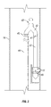
- FIG. 2 illustrates a gas lift system according to an exemplary embodiment of the present disclosure
- FIG. 3 illustrates a turn-over suspension mandrel according to an exemplary embodiment of the present disclosure
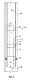
- FIG. 4 illustrates a gas lift system according to an alternative exemplary embodiment of the present disclosure.
- FIG. 1 illustrates a gas lift system 10 according to the prior art.
- a production tubing 12 is run inside casing 14 as understood in the art.
- a series of side pocket mandrels 16 are connected, one atop the other, beneath the tubing 12.
- Side pocket mandrels are known in the art.
- a gas lift valve 22 is located within the lower end of the side pocket of each side pocket mandrel 16. Gas lift valves 22 operate to equalize the fluid pressure within tubing 12 and annulus 20. As such, gas lift valves 22 regulate the amount of gas injected from the annulus into the tubing 12, which is used to lift the production fluids to the surface. The operation of gas lift valves is known in the art.
- Tubing 12 is connected beneath the lowermost side pocket mandrel 16 and extends below a production packer 18 which seals the annulus 20 created between side pocket mandrels 16 and casing 14.
- Production packers are known in the art.
- Tubing 12 and side pocket mandrels 16 can be connected by any means known in the art.
- the lowest side pocket mandrel 16 and its associated gas lift valve 22 represent the lowermost injection point of gas lift system 10. As such, the lowermost injection point is located above packer 18.
- a perforations interval 24 is located below production packer 18 for retrieving production fluids.
- gas lift system 10 Once gas lift system 10 is completed downhole, gas is injected from the surface down through annulus 20. Packer 18 traps the gas within annulus 20, thereby creating a supercharged annulus 20 having pressurized gas within. As the pressure increases, the pressure within annulus 20 becomes sufficiently greater than the pressure inside side pocket mandrels 16 and/or tubing 12, thereby forcing gas lift valves 22 to open and the pressurized gas to flow into side pocket mandrels 16 where it assists in lifting the production fluids.
- the pressure threshold of valves 22 can be varied as desired.
- FIG. 2 illustrates a gas lift system 40 according to an exemplary embodiment of the present disclosure.
- tubing 12 again extends down inside casing 14 where a series of side pocket mandrels 16, attached one above the other, are connected beneath the tubing 12.
- Gas lift system 40 is illustrated as having three side pocket mandrels 16, however, those skilled in the art having the benefit of this disclosure realize any number of side pocket mandrels 16 may be utilized as desired.
- a packer 18 is landed beneath the lowermost side pocket mandrel 16 in order to seal the annulus 20 as previously discussed.
- a turn-over suspension mandrel 42 is connected to the gas lift valve 22 of the lowermost side pocket mandrel 16 via a compression fitting, roll-on connector or other suitable connector 41.
- turn-over suspension mandrel 42 may be connected to other side pocket mandrels 16 instead of the lowermost side pocket mandrel 16.
- Gas lift valve 22 has packing devices 47 and port 49 which operate to regulate the entrance of the pressurized gas from annulus 20 as known in the art. Gas lift valves are known in the art and those skilled in the art having the benefit of this disclosure realize a variety of gas lift valves can be utilized with the present disclosure.
- turn-over suspension mandrel 42 is constructed such that it turns over 180 degrees to connect to coil 44 via a compression fitting, roll-on connector or other suitable connector 45.
- Coil 44 can be, for example, a 3/4 or 1 inch diameter coil, however, those skilled in the art having the benefit of this disclosure realize a variety of coil diameters may be utilized.
- a fishing neck 43 is located atop turn-over suspension mandrel 42 to provide a means by which turn-over suspension mandrel 42 may be landed and retrieved if desired.
- the coil 44 extends from the turn-over suspension mandrel 42 down through the tubing 12 and into the perforated interval 24 below the packer 18.
- a plug 46 is connected to the bottom of coil 44 in order to seal coil during installation of the turn-over suspension mandrel 42 and prevent pressurized fluid from traveling back uphole via the coil 44.
- the coil 44 may be pressurized in order to remove plug 46, thereby enabling the pressurized gas to be communicated downhole.
- plug 46 may be, for example, an aluminum pump-out plug. Other types of plugs may be used such as, for example, frangible disks.
- gas lift valves 22 may be landed inside side pocket mandrels 16.
- a wireline tool such as for example, a kickover tool as understood in the art, is run down inside tubing 12 to side pocket mandrels 16 in order to jerk out the dummy valves and stab in gas lift valves 22 via a fishing neck on gas lift valves 22.
- the kickover tool is run down inside side pocket mandrels 16, it is actuated such that its profile changes to allow it to reach over in to the side pocket of side pocket mandrel 16, the operation of which is known in the art.
- Those skilled in the art having the benefit of this disclosure realize there are a number of methods by which gas lift valves 22 may be landed inside side pocket mandrels 16.
- turn-over suspension mandrel 42 is also run downhole using the wireline tool and connected to gas lift valve 22. Also, before turn-over suspension mandrel 42 is run downhole, coil 44 has already been connected thereto. Once turn-over suspension mandrel 42 is landed, coil 44 will become pressurized from the annulus, thus forcing plug 46 off the end of coil 44, thereby enabling subsequent communication.
- plug 46 can be an aluminum pump-out plug which will dissolve within the downhole environment.
- gas lift valves 22 seek to equalize the pressure between tubing 12 and annulus 20. However, unlike the other upper gas lift valves 22 that do not have turn-over suspension mandrel 42 connected thereto, the lowermost gas lift valve 22 senses the tubing pressure via coil 44, which extends down into the wellbore beneath packer 18. Once the pressure in annulus 20 becomes sufficiently greater than the pressure inside coil 44, gas lift valve 22 of the lowermost side pocket mandrel 16 opens, allowing the pressurized gas to travel into lowermost side pocket mandrel 16 via port 49.
- gas lift system 40 provides a gas injection point below production packer 18.
- FIG. 4 illustrates an alternative exemplary embodiment of the present disclosure used in conjunction with a pack off assembly 60.
- a production tubing 62 is located inside casing 64.
- Pack off assembly 60 is landed inside production tubing 62, as known in the art, and includes a longitudinal bore 67 there-through for production flow.
- a production packer 63 is located below pack-off assembly 60 to seal the annulus between tubing 62 and casing 64.
- Pack-off assembly 60 includes an upper packer element 66 and a lower packer element 68.
- a perforation 75 is positioned in production tubing 62 along the tubing interval between upper packer 66 and lower packer 68.
- Pack-off assembly 60 includes a gas inlet port 70 located adjacent the perforation 75 in tubing 62.
- Gas inlet port 70 provides fluid communication from perforation 75 down through the body of pack-off assembly 60 via a gun drill 77 and to a gas lift valve 72, also located along the body of pack-off assembly 60.
- the construction and operation of pack-off assemblies are known in the art.
- a coil 74 may be connected to gas lift valve 72 via a suitable connector, such as a compression fitting (not shown).
- coil 74 is connected to the distal end of gas lift valve 72.
- Coil 74 extends down from gas lift valve 72 past production packer 63 and down into perforations 76, as illustrated in FIG. 4 .
- a plug 78 is attached to the end of coil 74, as discussed previously. Accordingly, the compressed gas flowing into the perforated tubing 62 and gas inlet port 70 of pack-off assembly 60, can be introduced below production packer 63 in order to provide a deepened location for gas lift.
Landscapes
- Geology (AREA)
- Life Sciences & Earth Sciences (AREA)
- Engineering & Computer Science (AREA)
- Mining & Mineral Resources (AREA)
- Environmental & Geological Engineering (AREA)
- Fluid Mechanics (AREA)
- Physics & Mathematics (AREA)
- General Life Sciences & Earth Sciences (AREA)
- Geochemistry & Mineralogy (AREA)
- Filling Or Discharging Of Gas Storage Vessels (AREA)
- Pipe Accessories (AREA)
- Lift Valve (AREA)
- Load-Engaging Elements For Cranes (AREA)
Applications Claiming Priority (1)
| Application Number | Priority Date | Filing Date | Title |
|---|---|---|---|
| US4384008P | 2008-04-10 | 2008-04-10 |
Publications (2)
| Publication Number | Publication Date |
|---|---|
| EP2110509A2 true EP2110509A2 (de) | 2009-10-21 |
| EP2110509A3 EP2110509A3 (de) | 2011-08-24 |
Family
ID=41026365
Family Applications (1)
| Application Number | Title | Priority Date | Filing Date |
|---|---|---|---|
| EP09157310A Withdrawn EP2110509A3 (de) | 2008-04-10 | 2009-04-03 | System und Verfahren zur Durchgangsrohrleitungsvertiefung einer Gasliftförderung |
Country Status (6)
| Country | Link |
|---|---|
| US (1) | US7954551B2 (de) |
| EP (1) | EP2110509A3 (de) |
| AU (1) | AU2009201332B2 (de) |
| BR (1) | BRPI0900740A2 (de) |
| CA (1) | CA2660219C (de) |
| MX (1) | MX2009003787A (de) |
Cited By (1)
| Publication number | Priority date | Publication date | Assignee | Title |
|---|---|---|---|---|
| EP2818630A1 (de) * | 2013-06-26 | 2014-12-31 | Welltec A/S | Gasauftriebsanlage und Gasauftriebsverfahren |
Families Citing this family (53)
| Publication number | Priority date | Publication date | Assignee | Title |
|---|---|---|---|---|
| US9682425B2 (en) | 2009-12-08 | 2017-06-20 | Baker Hughes Incorporated | Coated metallic powder and method of making the same |
| US8403037B2 (en) | 2009-12-08 | 2013-03-26 | Baker Hughes Incorporated | Dissolvable tool and method |
| US8327931B2 (en) | 2009-12-08 | 2012-12-11 | Baker Hughes Incorporated | Multi-component disappearing tripping ball and method for making the same |
| US9079246B2 (en) | 2009-12-08 | 2015-07-14 | Baker Hughes Incorporated | Method of making a nanomatrix powder metal compact |
| US9101978B2 (en) | 2002-12-08 | 2015-08-11 | Baker Hughes Incorporated | Nanomatrix powder metal compact |
| US9109429B2 (en) | 2002-12-08 | 2015-08-18 | Baker Hughes Incorporated | Engineered powder compact composite material |
| US10240419B2 (en) | 2009-12-08 | 2019-03-26 | Baker Hughes, A Ge Company, Llc | Downhole flow inhibition tool and method of unplugging a seat |
| US9243475B2 (en) | 2009-12-08 | 2016-01-26 | Baker Hughes Incorporated | Extruded powder metal compact |
| US9227243B2 (en) | 2009-12-08 | 2016-01-05 | Baker Hughes Incorporated | Method of making a powder metal compact |
| US9127515B2 (en) | 2010-10-27 | 2015-09-08 | Baker Hughes Incorporated | Nanomatrix carbon composite |
| US8528633B2 (en) | 2009-12-08 | 2013-09-10 | Baker Hughes Incorporated | Dissolvable tool and method |
| US8651188B2 (en) * | 2009-12-30 | 2014-02-18 | Schlumberger Technology Corporation | Gas lift barrier valve |
| US8776884B2 (en) | 2010-08-09 | 2014-07-15 | Baker Hughes Incorporated | Formation treatment system and method |
| US9090955B2 (en) | 2010-10-27 | 2015-07-28 | Baker Hughes Incorporated | Nanomatrix powder metal composite |
| US20120211239A1 (en) * | 2011-02-18 | 2012-08-23 | Baker Hughes Incorporated | Apparatus and method for controlling gas lift assemblies |
| US9080098B2 (en) | 2011-04-28 | 2015-07-14 | Baker Hughes Incorporated | Functionally gradient composite article |
| US8631876B2 (en) | 2011-04-28 | 2014-01-21 | Baker Hughes Incorporated | Method of making and using a functionally gradient composite tool |
| US8631875B2 (en) | 2011-06-07 | 2014-01-21 | Baker Hughes Incorporated | Insert gas lift injection assembly for retrofitting string for alternative injection location |
| US9139928B2 (en) | 2011-06-17 | 2015-09-22 | Baker Hughes Incorporated | Corrodible downhole article and method of removing the article from downhole environment |
| EP2729658B1 (de) | 2011-07-06 | 2017-09-27 | Shell Internationale Research Maatschappij B.V. | System und verfahren zum einspritzen eines behandlungsfluids in ein bohrloch und einspritzventil für das behandlungsfluid |
| US9707739B2 (en) | 2011-07-22 | 2017-07-18 | Baker Hughes Incorporated | Intermetallic metallic composite, method of manufacture thereof and articles comprising the same |
| US8783365B2 (en) | 2011-07-28 | 2014-07-22 | Baker Hughes Incorporated | Selective hydraulic fracturing tool and method thereof |
| US9643250B2 (en) | 2011-07-29 | 2017-05-09 | Baker Hughes Incorporated | Method of controlling the corrosion rate of alloy particles, alloy particle with controlled corrosion rate, and articles comprising the particle |
| US9833838B2 (en) | 2011-07-29 | 2017-12-05 | Baker Hughes, A Ge Company, Llc | Method of controlling the corrosion rate of alloy particles, alloy particle with controlled corrosion rate, and articles comprising the particle |
| US9057242B2 (en) | 2011-08-05 | 2015-06-16 | Baker Hughes Incorporated | Method of controlling corrosion rate in downhole article, and downhole article having controlled corrosion rate |
| US9033055B2 (en) | 2011-08-17 | 2015-05-19 | Baker Hughes Incorporated | Selectively degradable passage restriction and method |
| US9090956B2 (en) | 2011-08-30 | 2015-07-28 | Baker Hughes Incorporated | Aluminum alloy powder metal compact |
| US9109269B2 (en) | 2011-08-30 | 2015-08-18 | Baker Hughes Incorporated | Magnesium alloy powder metal compact |
| US9856547B2 (en) | 2011-08-30 | 2018-01-02 | Bakers Hughes, A Ge Company, Llc | Nanostructured powder metal compact |
| US9643144B2 (en) | 2011-09-02 | 2017-05-09 | Baker Hughes Incorporated | Method to generate and disperse nanostructures in a composite material |
| US9133695B2 (en) | 2011-09-03 | 2015-09-15 | Baker Hughes Incorporated | Degradable shaped charge and perforating gun system |
| US9347119B2 (en) | 2011-09-03 | 2016-05-24 | Baker Hughes Incorporated | Degradable high shock impedance material |
| US9187990B2 (en) | 2011-09-03 | 2015-11-17 | Baker Hughes Incorporated | Method of using a degradable shaped charge and perforating gun system |
| CN103930647B (zh) | 2011-11-08 | 2017-11-17 | 国际壳牌研究有限公司 | 用于烃井的阀,设置有该阀的烃井以及该阀的应用 |
| US9010416B2 (en) | 2012-01-25 | 2015-04-21 | Baker Hughes Incorporated | Tubular anchoring system and a seat for use in the same |
| US9068428B2 (en) | 2012-02-13 | 2015-06-30 | Baker Hughes Incorporated | Selectively corrodible downhole article and method of use |
| EP2815060A1 (de) | 2012-02-14 | 2014-12-24 | Shell Internationale Research Maatschappij B.V. | Verfahren zur herstellung von kohlenwasserstoffgas aus einem bohrloch und ventilanordnung |
| US9605508B2 (en) | 2012-05-08 | 2017-03-28 | Baker Hughes Incorporated | Disintegrable and conformable metallic seal, and method of making the same |
| WO2014197848A1 (en) * | 2013-06-07 | 2014-12-11 | Drover Energy Services Llc | Device and method for improving gas lift |
| US9470074B2 (en) * | 2013-06-07 | 2016-10-18 | Drover Energy Services Llc | Device and method for improving gas lift |
| US9816339B2 (en) | 2013-09-03 | 2017-11-14 | Baker Hughes, A Ge Company, Llc | Plug reception assembly and method of reducing restriction in a borehole |
| WO2015127174A1 (en) | 2014-02-21 | 2015-08-27 | Terves, Inc. | Fluid activated disintegrating metal system |
| US11167343B2 (en) | 2014-02-21 | 2021-11-09 | Terves, Llc | Galvanically-active in situ formed particles for controlled rate dissolving tools |
| US10689740B2 (en) | 2014-04-18 | 2020-06-23 | Terves, LLCq | Galvanically-active in situ formed particles for controlled rate dissolving tools |
| US20170226831A1 (en) * | 2014-10-17 | 2017-08-10 | Shell Oil Company | Downhole lift gas injection system |
| US9910026B2 (en) | 2015-01-21 | 2018-03-06 | Baker Hughes, A Ge Company, Llc | High temperature tracers for downhole detection of produced water |
| US10378303B2 (en) | 2015-03-05 | 2019-08-13 | Baker Hughes, A Ge Company, Llc | Downhole tool and method of forming the same |
| US10221637B2 (en) | 2015-08-11 | 2019-03-05 | Baker Hughes, A Ge Company, Llc | Methods of manufacturing dissolvable tools via liquid-solid state molding |
| US10016810B2 (en) | 2015-12-14 | 2018-07-10 | Baker Hughes, A Ge Company, Llc | Methods of manufacturing degradable tools using a galvanic carrier and tools manufactured thereof |
| CA3012511A1 (en) | 2017-07-27 | 2019-01-27 | Terves Inc. | Degradable metal matrix composite |
| US11242733B2 (en) | 2019-08-23 | 2022-02-08 | Baker Hughes Oilfield Operations Llc | Method and apparatus for producing well with backup gas lift and an electrical submersible well pump |
| CN110965962B (zh) * | 2019-11-29 | 2022-05-06 | 中国石油集团川庆钻探工程有限公司 | 封存气井复产解封方法 |
| US11566502B2 (en) | 2021-06-10 | 2023-01-31 | Weatherford Technology Holdings, Llc | Gas lift system |
Family Cites Families (49)
| Publication number | Priority date | Publication date | Assignee | Title |
|---|---|---|---|---|
| US12143A (en) * | 1855-01-02 | Life-preserving raft | ||
| US1737894A (en) * | 1927-06-27 | 1929-12-03 | Edward P Reynolds | Method of flowing oil |
| US2416842A (en) * | 1941-07-01 | 1947-03-04 | Herbert C Otis | Well cementing apparatus |
| US2948232A (en) * | 1957-07-18 | 1960-08-09 | John H Mccarvell | Gas lift method and apparatus |
| US3109376A (en) * | 1959-08-10 | 1963-11-05 | William P Massey | Method and apparatus for producing oil from multiple strata from single well bore |
| US3278192A (en) * | 1962-10-08 | 1966-10-11 | Otis Eng Co | Sealing devices |
| US4022273A (en) * | 1975-10-10 | 1977-05-10 | Cook Testing Co. | Bottom hole flow control apparatus |
| US4258787A (en) * | 1979-07-11 | 1981-03-31 | Baker International Corporation | Subterranean well injection apparatus |
| US4387767A (en) * | 1980-11-13 | 1983-06-14 | Dresser Industries, Inc. | Subsurface safety valve system with hydraulic packer |
| US4490095A (en) * | 1981-11-19 | 1984-12-25 | Soderberg Paul B | Oilwell pump system and method |
| US4646827A (en) * | 1983-10-26 | 1987-03-03 | Cobb William O | Tubing anchor assembly |
| US4545731A (en) * | 1984-02-03 | 1985-10-08 | Otis Engineering Corporation | Method and apparatus for producing a well |
| US4589482A (en) * | 1984-06-04 | 1986-05-20 | Otis Engineering Corporation | Well production system |
| US4616981A (en) * | 1984-10-19 | 1986-10-14 | Simmons Eugene D | Pumping apparatus with a down-hale spring loaded piston actuated by fluid pressure |
| US4632184A (en) * | 1985-10-21 | 1986-12-30 | Otis Engineering Corporation | Submersible pump safety systems |
| US4685523A (en) * | 1986-05-06 | 1987-08-11 | Otis Engineering Corporation | Removable side pocket mandrel |
| US4718488A (en) * | 1987-03-12 | 1988-01-12 | Camco, Incorporated | Pump-out plug system for a well conduit |
| US5092400A (en) * | 1989-06-08 | 1992-03-03 | Fritz Jagert | Coiled tubing hanger |
| US5148865A (en) * | 1991-04-08 | 1992-09-22 | Reed Lehman T | Multi-conversion wellhead assembly |
| US5203409A (en) * | 1992-01-27 | 1993-04-20 | Cooper Industries, Inc. | Geothermal well apparatus and eccentric hanger spool therefor |
| DE69319239T2 (de) | 1993-08-04 | 1998-10-22 | Cooper Cameron Corp | Elektrische Verbindung |
| US5522464A (en) * | 1995-05-12 | 1996-06-04 | Piper Oilfield Products, Inc. | Hydraulic tubing head assembly |
| US5727631A (en) * | 1996-03-12 | 1998-03-17 | Total Tool, Inc. | Coiled tubing hanger |
| US5662169A (en) * | 1996-05-02 | 1997-09-02 | Abb Vetco Gray Inc. | Cuttings injection wellhead system |
| AU3550997A (en) | 1997-07-14 | 1999-02-10 | Axtech Ltd | Simultaneous production and water injection well system |
| US5915475A (en) * | 1997-07-22 | 1999-06-29 | Wells; Edward A. | Down hole well pumping apparatus and method |
| AU9791898A (en) * | 1997-10-07 | 1999-04-27 | Fmc Corporation | Slimbore subsea completion system and method |
| US6467541B1 (en) * | 1999-05-14 | 2002-10-22 | Edward A. Wells | Plunger lift method and apparatus |
| GB2361722A (en) * | 1999-12-14 | 2001-10-31 | Helix Well Technologies Ltd | Gas lift conduit apparatus for increasing effective depth of gas lift |
| US7025132B2 (en) * | 2000-03-24 | 2006-04-11 | Fmc Technologies, Inc. | Flow completion apparatus |
| EP1278935B1 (de) * | 2000-03-24 | 2006-06-21 | FMC Technologies, Inc. | Dichtungsanordnung für eine tubingaufhängung |
| CA2310236C (en) | 2000-06-09 | 2005-05-10 | Stephen Michael Komistek | Tubing cleanout spool |
| US6457530B1 (en) * | 2001-03-23 | 2002-10-01 | Stream-Flo Industries, Ltd. | Wellhead production pumping tree |
| US6763891B2 (en) | 2001-07-27 | 2004-07-20 | Abb Vetco Gray Inc. | Production tree with multiple safety barriers |
| US6688386B2 (en) * | 2002-01-18 | 2004-02-10 | Stream-Flo Industries Ltd. | Tubing hanger and adapter assembly |
| US6966383B2 (en) * | 2002-12-12 | 2005-11-22 | Dril-Quip, Inc. | Horizontal spool tree with improved porting |
| US6851478B2 (en) * | 2003-02-07 | 2005-02-08 | Stream-Flo Industries, Ltd. | Y-body Christmas tree for use with coil tubing |
| US6830108B2 (en) * | 2003-05-01 | 2004-12-14 | Delaware Capital Formation, Inc. | Plunger enhanced chamber lift for well installations |
| US20040262010A1 (en) * | 2003-06-26 | 2004-12-30 | Milberger Lionel J. | Horizontal tree assembly |
| US20050175476A1 (en) * | 2004-02-09 | 2005-08-11 | Energy Xtraction Corporation | Gas well liquid recovery |
| GB2413600A (en) * | 2004-04-30 | 2005-11-02 | Leslie Eric Jordan | Hydraulically powered borehole pump |
| US7252148B2 (en) * | 2004-07-08 | 2007-08-07 | Smith International, Inc. | Plunger actuated pumping system |
| US7367401B2 (en) * | 2004-11-29 | 2008-05-06 | Smith International, Inc. | Ported velocity tube for gas lift operations |
| CA2497090C (en) | 2005-02-15 | 2009-09-15 | Donald Sieben | Coil tubing hanger and method of using same |
| US7325600B2 (en) * | 2005-02-15 | 2008-02-05 | Bj Services Company, U.S.A. | Coil tubing hanger and method of using same |
| US7699099B2 (en) * | 2006-08-02 | 2010-04-20 | B.J. Services Company, U.S.A. | Modified Christmas tree components and associated methods for using coiled tubing in a well |
| US7770637B2 (en) * | 2007-10-12 | 2010-08-10 | Ptt Exploration And Production Public Company Limited | Bypass gas lift system and method for producing a well |
| US8006756B2 (en) * | 2007-12-10 | 2011-08-30 | Evolution Petroleum Corporation | Gas assisted downhole pump |
| US7766085B2 (en) * | 2008-02-04 | 2010-08-03 | Marathon Oil Company | Apparatus, assembly and process for injecting fluid into a subterranean well |
-
2009
- 2009-03-26 CA CA2660219A patent/CA2660219C/en not_active Expired - Fee Related
- 2009-04-03 EP EP09157310A patent/EP2110509A3/de not_active Withdrawn
- 2009-04-06 AU AU2009201332A patent/AU2009201332B2/en not_active Ceased
- 2009-04-07 BR BRPI0900740-7A patent/BRPI0900740A2/pt not_active IP Right Cessation
- 2009-04-08 MX MX2009003787A patent/MX2009003787A/es active IP Right Grant
- 2009-04-08 US US12/420,425 patent/US7954551B2/en active Active
Cited By (4)
| Publication number | Priority date | Publication date | Assignee | Title |
|---|---|---|---|---|
| EP2818630A1 (de) * | 2013-06-26 | 2014-12-31 | Welltec A/S | Gasauftriebsanlage und Gasauftriebsverfahren |
| WO2014207025A3 (en) * | 2013-06-26 | 2015-06-18 | Welltec A/S | A gas lift system and a gas lift method |
| CN105283630A (zh) * | 2013-06-26 | 2016-01-27 | 韦尔泰克有限公司 | 气举系统和气举方法 |
| AU2014301129B2 (en) * | 2013-06-26 | 2017-04-13 | Welltec A/S | A gas lift system and a gas lift method |
Also Published As
| Publication number | Publication date |
|---|---|
| US7954551B2 (en) | 2011-06-07 |
| BRPI0900740A2 (pt) | 2009-12-01 |
| MX2009003787A (es) | 2009-11-26 |
| AU2009201332B2 (en) | 2011-06-30 |
| CA2660219C (en) | 2012-08-28 |
| CA2660219A1 (en) | 2009-10-10 |
| US20090255684A1 (en) | 2009-10-15 |
| AU2009201332A1 (en) | 2009-10-29 |
| EP2110509A3 (de) | 2011-08-24 |
Similar Documents
| Publication | Publication Date | Title |
|---|---|---|
| US7954551B2 (en) | System and method for thru tubing deepening of gas lift | |
| US7823634B2 (en) | Wellhead isolation sleeve assembly | |
| US9970257B2 (en) | One-trip method of plugging a borehole for well abandonment | |
| US20080135248A1 (en) | Method and apparatus for completing and fluid treating a wellbore | |
| US20080156498A1 (en) | Hydraulically Controlled Burst Disk Subs (Hcbs) | |
| US20090159279A1 (en) | Methods and systems for completing multi-zone openhole formations | |
| US20110162843A1 (en) | Process and apparatus to improve reliability of pinpoint stimulation operations | |
| AU3440202A (en) | Well completion method and apparatus | |
| US9587456B2 (en) | Packer setting method using disintegrating plug | |
| US8631875B2 (en) | Insert gas lift injection assembly for retrofitting string for alternative injection location | |
| US9957777B2 (en) | Frac plug and methods of use | |
| US9022114B2 (en) | Cement shoe and method of cementing well with open hole below the shoe | |
| US20150000921A1 (en) | Well Bore Stimulation Valve | |
| CA2999197C (en) | Method of well completion | |
| US9228405B2 (en) | Velocity strings | |
| US20030056958A1 (en) | Gas lift assembly | |
| US10151189B2 (en) | Single trip—through drill pipe proppant fracturing method for multiple cemented-in frac sleeves | |
| US20160369603A1 (en) | Redressing method and redressed completion system | |
| CN101365863A (zh) | 压力抑制装置和其使用方法 | |
| GB2406348A (en) | Removal of cement residue obstruction |
Legal Events
| Date | Code | Title | Description |
|---|---|---|---|
| PUAI | Public reference made under article 153(3) epc to a published international application that has entered the european phase |
Free format text: ORIGINAL CODE: 0009012 |
|
| 17P | Request for examination filed |
Effective date: 20090403 |
|
| AK | Designated contracting states |
Kind code of ref document: A2 Designated state(s): AT BE BG CH CY CZ DE DK EE ES FI FR GB GR HR HU IE IS IT LI LT LU LV MC MK MT NL NO PL PT RO SE SI SK TR |
|
| PUAL | Search report despatched |
Free format text: ORIGINAL CODE: 0009013 |
|
| AK | Designated contracting states |
Kind code of ref document: A3 Designated state(s): AT BE BG CH CY CZ DE DK EE ES FI FR GB GR HR HU IE IS IT LI LT LU LV MC MK MT NL NO PL PT RO SE SI SK TR |
|
| RIC1 | Information provided on ipc code assigned before grant |
Ipc: E21B 43/12 20060101AFI20110721BHEP |
|
| 17Q | First examination report despatched |
Effective date: 20130109 |
|
| STAA | Information on the status of an ep patent application or granted ep patent |
Free format text: STATUS: THE APPLICATION IS DEEMED TO BE WITHDRAWN |
|
| 18D | Application deemed to be withdrawn |
Effective date: 20130522 |